

TOPP C30S/230V, C30S/24V Installation And Instructions Manual
C30S
INSTALLATION AND USE INSTRUCTIONS
CHAIN ACTUATOR FOR
WINDOW AUTOMATION
PATENTED
BEFORE INSTALLING AND USING THE ACTUATOR, IT IS
COMPULSORY FOR THE INSTALLER AND THE USER TO READ
AND UNDERSTAND THIS MANUAL IN ALL ITS PARTS.
THIS MANUAL IS INTEGRAL PART OF THE ACTUATOR
AND MUST BE PRESERVED FOR FUTURE REFERENCE
UNTIL DEMOLITION OF THE SAME.
VER.0.0
REV.02.18
P/N 0P5311
original instructions


INDEX
1- EC DECLARATION OF INCORPORATION OF PARTLY COMPLETED
MACHINERY
........................................................................................................................page 04
2- GENERAL REMARKS
2.1- General instructions..........................................................................................page 05
2.2- Installer and user ..............................................................................................page 05
2.3- Technical assistance.........................................................................................page 05
2.4- Reserved rights ................................................................................................page 06
2.5- Description of personnel...................................................................................page 06
3- TECHNICAL DESCRIPTION
3.1- Rating plate and "CE" marking.........................................................................page 07
3.2- Denomination of the components and dimensions ..........................................page 08
3.3- Technical data...................................................................................................page 09
3.4- Formulas for the calculation of thrust force or tractive force ............................page 10
3.5- Destination of use.............................................................................................page 10
3.6- Use Limits.........................................................................................................page 11
3.7- Package............................................................................................................page 11
4- SAFETY
4.1- General instructions .........................................................................................page 13
4.2- Safety Devices .................................................................................................page 13
4.2.1- Protections against electric hazard ...............................................................page 13
4.3- Safety plates.....................................................................................................page 14
4.4- Residual risks ...................................................................................................page 14
5- INSTALLATION
5.1- General instructions .........................................................................................page 15
5.2- Top hung windows............................................................................................page 18
5.3- Bottom hung windows ......................................................................................page 19
5.4- Electrical Connections......................................................................................page 20
5.5- Control devices.................................................................................................page 21
5.6- Emergency procedures ....................................................................................page 22
6- USE AND OPERATION
6.1- Use of the actuator ...........................................................................................page 23
6.2- Smart Reset System (SAI)..............................................................................page 24
7- MAINTENANCE
7.1- General instructions .........................................................................................page 25
8- DEMOLITION
8.1- General instructions .........................................................................................page 25
9- SPARE PARTS AND ACCESSORIES UPON REQUEST
9.1- General instructions .........................................................................................page 25
FIGURES
........................................................................................................................page 26
3
C30S
INSTALLATION AND USE ISTRUCTIONS

4
C30S
INSTALLATION AND USE ISTRUCTIONS
1- EC DECLARATION OF INCORPORATION OF PARTLY COMPLETED MACHINERY
ORIGINAL
The undersigned, in the name of and
behalf of the following company
Topp S.r.l.
Via Galvani, 59
36066 Sandrigo (VI)
Italia
herewith declares that the person authorised to compile the technical file is
Name: Bettiati Roberto - Topp S.r.l.
Address: via Galvani,59 36066 Sandrigo (VI)
and that to the partly completed machinery
CHAIN ACTUATOR FOR WINDOW AUTOMATION
Type: C30S
Model: C30S/230V - C30S/24V
the following essential requisites of the
2006/42/EC Machinery Directive (including all applicable amendments)
have been applied and fulfilled: Enclosure I: 1.5.1; 1.5.2; 1.5.10; 1.5.11
that the relevant technical documentation is compiled in accordance with part B of Annex VII of the above
mentioned Machinery Directive..
The above identified partly completed machinery is also in conformity with the all the relevant provisions
of the following directives (including all applicable amendments)
EMC Directive 2014/30/EU
RoHS II Directive 2011/65/EU
The following harmonised standards have been applied:
EN 60335-2-103:2015 (applicable parts)
EN 55014-1:2006 + A1:2009 + A2:2011
EN 55014-2:2015
EN 61000-6-2:2005.
EN 61000-6-3:2007 + A1:2011 + AC:2012.
EN 50581:2012
and the following technical documents:
EN 62233:2008
The undersigned also undertakes the obligation, in response to a duly reasoned request by the national
market surveillance authorities, to transmit to the a.m. authorities, in electronic or paper format, the
relevant technical documentation on the partly completed machinery.
The above identified partly completed machinery must not be put into service until the final machinery
into which it is to be incorporated has been declared in conformity with the provisions of the above
mentioned Machinery Directive.
This declaration of conformity is issued under the sole responsibility of the manufacturer.
Date: Sandrigo01/02/2018 Signature: Matteo Cavalcante
Amministratore ................................................................

5
C30S
GENERAL REMARKS -2
2.1- GENERAL INSTRUCTIONS
BEFORE INSTALLING AND USING THE ACTUATOR, IT IS COMPULSORY THAT THE
INSTALLER AND THE USER CAREFULLY READ AND UNDERSTAND THIS MANUAL
IN ALL ITS PARTS.
THIS MANUAL IS INTEGRAL PART OF THE ACTUATOR AND MUST COMPULSORILY
BE PRESERVED FOR FUTURE REFERENCE.
THE MANUFACTURER HAS NO LIABILITY FOR ANY EVENTUAL DAMAGE TO
PERSONS, ANIMALS AND THINGS DUE TO THE INOBSERVANCE OF THE
PRESCRIPTIONS DESCRIBED IN THIS MANUAL.
IN ORDE R FOR THE A UTOM ATION UNIT TO OPERATE CORRECTLY, WE
RECOMMEND CARRYING OUT PERIODICAL MAINTENANCE ON IT, AS INDICATED IN
PAR. 7.1 OF THIS MANUAL.
THE WARRANTY ON THE ACTUATOR WILL NOT BE HONORED IF PRODUCT IS NOT
INSTALLED AND USED ACCORDING TO THE INSTRUCTIONS PROVIDED AND THE
REGULATIONS SHOWN IN THIS INSTRUCTION MANUAL AND IF IT IS USED WITH NONGENUINE PARTS, ACCESSORIES, SPARE PARTS AND/OR CONTROL/FEEDING UNITS.
2.2- INSTALLER AND USER
THE ACTU ATOR INSTAL LATION CAN BE PER FORMED EXCLUSIV ELY BY
COMPET ENT AND QUALIFI ED TECHNICAL PERSONNEL SATISFYING THE
PROFESSIONAL AND TECHNICAL REQUIREMENTS FORESEEN BY THE LAWS IN
FORCE IN THE COUNTRY OF INSTALLATION.
THE INSTALLATION TECHNICIAN SHALL ACCEPT FULL RESPONSIBILITY FOR ANY
INSTA L LAT I O N E R R O R S AND FOR AN Y FAILURE TO ADHERE T O T H E
INSTRUCTIONS PROVIDED IN THIS MANUAL. THE INSTALLATION TECHNICIAN
SHALL THEREFORE BE EXCLUSIVELY LIABLE FOR ANY DAMAGES CAUSED TO
USERS AND/OR THIRD PARTIES THAT MAY ARISE AS A RESULT OF INCORRECT
INSTALLATION.
THE ACTUATOR CAN BE USED EXCLUSIVELY BY A USER ACTING IN COMPLIANCE
WITH THE INSTRUCTIONS CONTAINED IN THIS MANUAL AND/OR IN THE MANUAL
OF THE ACTUATOR CONTROL DEVICE (e.g.: CONTROL UNIT).
2.3- TECHNICAL ASSISTANCE
Contact the installation technician or retailer for assistance.
INSTALLATION AND USE ISTRUCTIONS
2.4- RESERVED RIGHTS
The reserved rights on this manual "Installation and use instructions" remain property of
the Manufacturer.
Each information herein contained (text, drawings, diagrams, etc.) is reserved.
None part of this manual can be reproduced and disclosed (totally or partially) by any
reproduction means (photocopies, microfilms or other) without written authorization of
the Manufacturer.
2.5- DESCRIPTION OF PERSONNEL
USERS MUST NEVER PERFORM OPERATIONS RESERVED FOR MAINTENANCE
PEOPLE OR SPECIALISED TECHNICIANS. THE MANUFACTURER DECLINES ALL
LIABILITY FOR DAMAGE DERIVING FROM FAILURE TO OBSERVE THE ABOVE
REQUIREMENTS.
Specialised electrician:
A specialised electrician must be able to install the actuator, start it and operate it both
in normal conditions and in the maintenance mode; he/she is qualified to perform all
electrical and mechanical adjustment and maintenance operations. He/she is allowed
to work on live electrical cabinets and junction boxes.
User:
specialised person capable of operating the actuator under normal conditions by using
the relative controls. He/she must also be able to operate with the actuator under
“maintenance” in order to perform simple routine maintenance operations (cleaning),
and start or reset the actuator following an unscheduled stop.
6
2- GENERAL REMARKS
INSTALLATION AND USE ISTRUCTIONS
C30S

3.1- RATING PLATE AND "CE" MARKING
The "CE" marking certifies the compliance of the machine with the essential safety and
health requirements foreseen by the product European Directives.
The rating plate is an adhesive plate in polyester, silk-screen printed in black, having the
following size: L= 50 mm - H= 36 mm.
It is applied externally on the actuator. The plate bears in readable and indelible way the
following data:
• logo and address of the manufacturer
• type and model
• voltage and intensity of power supply (V - A)
• type of service S (min)
2
• absorbed electric power P (W)
• thrust and tractive force F (N)
• idle translation speed (mm/s)
• protection degree (IP)
• symbol of double insulation (only for mod. C30S/230V)
• "CE" marking
• symbol of “WEEE” Directive 2002/96/CE
• serial number
7
C30S
TECHNICAL DESCRIPTION -3
INSTALLATION AND USE ISTRUCTIONS
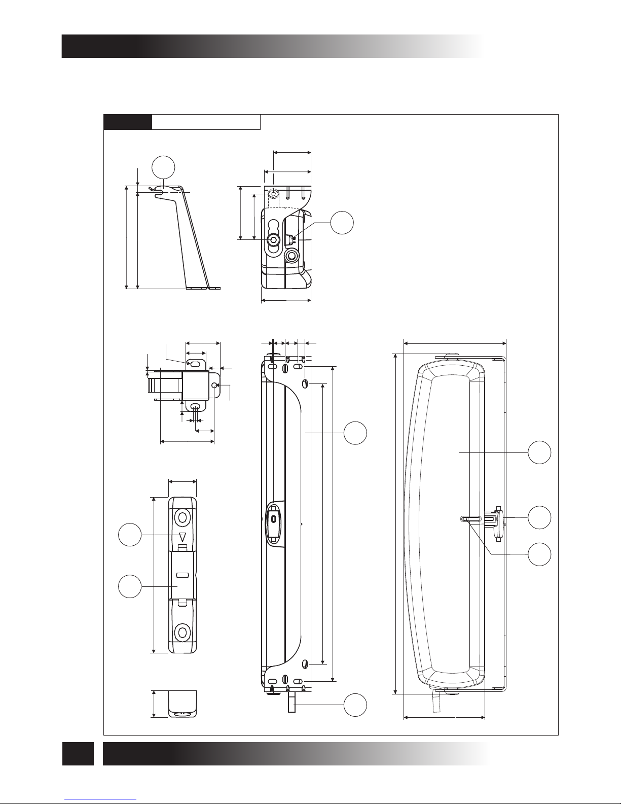
3.2- DENOMINATION OF THE COMPONENTS AND DIMENSIONS
Dimensions in mm
LEGEND:
1) Quick coupling
2) Slot side indicator
3) Bracket for bottom hung opening
4) Opening stroke adjustment
switch I= 200 mm; II= 380 mm
5) Connection bracket to the frame
6) Actuator
7) Chain adjustment end
8) Chain end adjustment screw
9) Power supply cable
8
C30S
3- TECHNICAL DESCRIPTION
INSTALLATION AND USE ISTRUCTIONS
Fig. 1
7
8
6
80
335.2
101
3
103
96.5
6.5
1.5
34.12
20
11
Ø5
Ø5
11
54
19
4
2
1
16
86
15
4
49
37
46
53
46
9
5
1 12 12
7
310
276
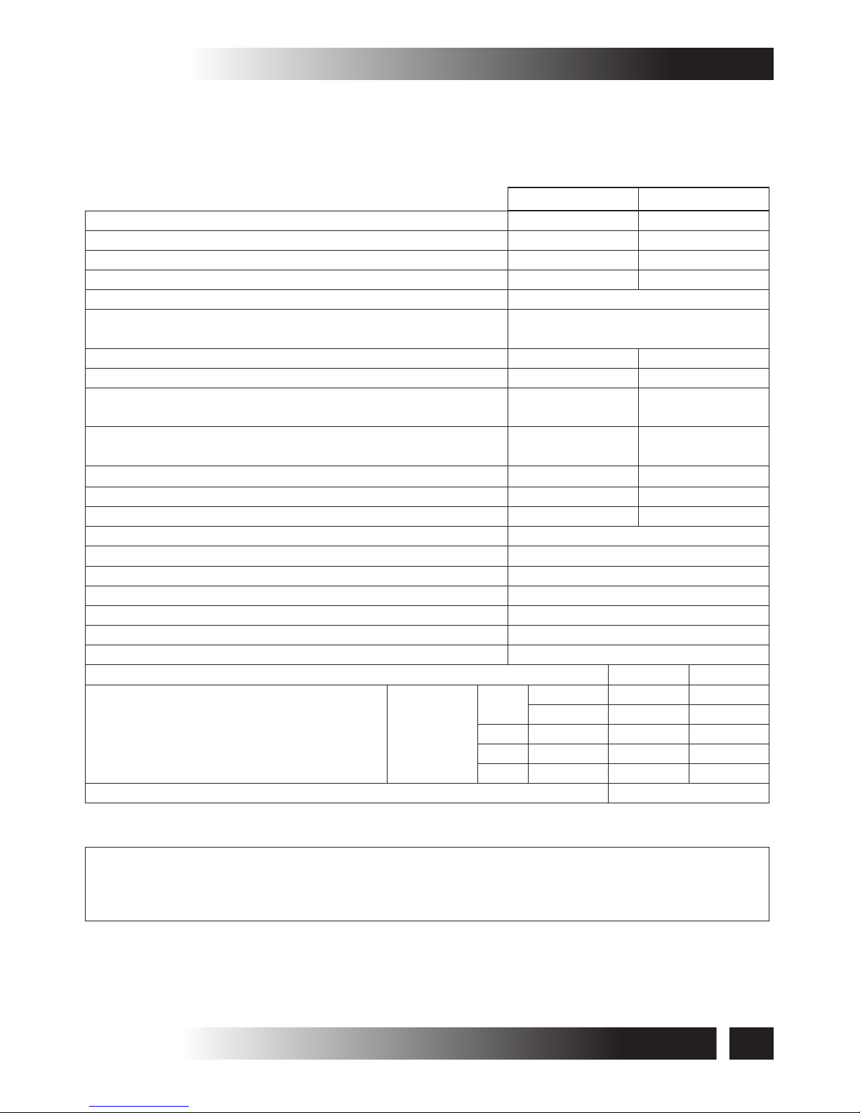
3.3- TECHNICAL DATA
Tab. 1 contains the technical data characterising the actuators.
9
C30S
TECHNICAL DESCRIPTION -3
INSTALLATION AND USE ISTRUCTIONS
MAXIMUM APPLICABLE THRUST LOAD
300 N
300 N
MAXIMUM APPLICABLE TRACTIVE LOAD
300 N
300 N
MAXIMUM THRUST LOAD APPLICABLE ON
TWO SYNCHRONIZED AUTOMATIONS.
500 N
500 N
MAXIMUM TRACTIVE LOAD APPLICABLE ON
TWO SYNCHRONIZED AUTOMATIONS
500 N
500 N
IDLE TRANSLATIO N SPEED
9,5 mm/s
9,5 mm/s
DURATION OF THE IDLE S TROKE
40 s
40 s
TYPE OF SERVICE S2
(1)
3 min
3 min
ADJUSTABLE STROKES ON OUTLET
(2)
200 mm / 380 mm
ADJUSTMENT OF THE WINDOW FRAME CONNECTION
AUTOMATIC
MAX. OVERLAPPED PART “D”
50 mm
OPERATING TEMPERATURE
-5°C ÷ 50°C
ACTUATOR WEIGHT WITH BRACKETS
1,1 kg
GROSS WEIGHT
1,5 kg
SYNCHRONIZ. TWO ACTUATORS ON THE SAME WINDOW
Yes
POWER SUPPLY VOLTAGE
230 V ~ 50 Hz
24 V ± 10%
ABSORBED CURRENT
0,15 A
0,55 A
ABSORBED POWER WITH LOAD
25 W
14 W
PROTECTION AGAINST ELECTRIC SHOCKS
Class II
Class III
PROTECTION DEGREE OF ELECTRIC DEVICES
IP30
PARALLEL CONNECTION OF MORE THAN ONE ACTUATOR
Yes
(See wiring diagram)
ADJUSTABLE STROKES ON OUTLET
200 mm 380 mm
MINIMUM HEIGHT OF THE WINDOW FRAME
(3)
Posion
assembly
brackets
0
Top hung
250 mm 500 mm
Boom hung
350 mm 1000 mm
1
Top hung
250 mm 400 mm
2
Top hung
350 mm 500 mm
3
Boom hung
500 mm 950 mm
MINIMUM DISTANCE BETWEEN ACTUATOR
60 mm
C30S/230V C30S/24V
(1)
Service of limited duration according to EN 60034
(2)
Tolerance on the tripping precision of the limit switch at output: ± 10 mm
(3)
Distance of the actuator from the window opening hinge valid only with max. stroke 380 mm
Tab. 1

3.5- DESTINATION OF USE
THE ACTUATOR HAS BEEN DESIGNED AND MANUFACTURED TO PERFORM, BY
MEANS OF A CONTROL DEVICE, THE OPENING AND CLOSING OF TOP HUNG
WINDOWS, BOTTOM HUNG WINDOWS, PIVOT WINDOWS, AND SKYLIGHTS.
3.4- FORMULAS FOR THE CALCULATION OF THRUST AND
TRACTIVE FORCE
Top hung windows (A) or
bottom hung windows (B)
F = Force necessary for opening or
closing
P = Weight of the window
(only movable part)
C = Window opening stroke
H = Window height (only movable part)
F = (0,54 x P) x ( )
C
H
P
F
H
C
B
P
F
H
C
A
F
P
Horizontal domes or skylights
F = Force necessary for opening or closing
P = Weight of the skylight or dome
(only movable part)
F = 0,54 x P
The C30S Chain actuator is equipped with the latest TOPP system for the coordinated
synchronization of the chain movement. The electronic speed control is fully automatic and
requires no external control unit; just connect the yellow/white/blue cables as per wiring diagram at
the back of the manual to achieve the synchronized mode. The Smart Reset System (SAI) has
also been included which adjusts the closure of the window in an optimum manner.
The C30S chain actuator is mounted when you need two or more attachment points because the
window is particularly heavy or wide and only one actuator would not allow perfect closure of the
window. It should be remembered that the force exerted by the actuators individually is the same
as a similar C30 actuator; for example, by mounting two actuators the force applied to the window
is, therefore, doubled. The window is moved in a uniform, synchronized and coordinated manner
with no interruptions and/or speed changes in the actuators' operation. In the event of any failure of
one of the actuators due to a mechanical or electrical fault, the others also stop operating,
guaranteeing that the window remains intact.
10
C30S
3- TECHNICAL DESCRIPTION
INSTALLATION AND USE ISTRUCTIONS
Fig. 2
Fig. 3
 Loading...