

INSTALLATION AND USE INSTRUCTIONS
CHAIN ACTUATOR FOR
WINDOW AUTOMATION
C30
PATENTED
P/N 0P5201
VER.1.0
BEFORE INSTALLING AND USING THE ACTUATOR, IT IS
COMPULSORY FOR THE INSTALLER AND THE USER TO READ
AND UNDERSTAND THIS MANUAL IN ALL ITS PARTS.
THIS MANUAL IS INTEGRAL PART OF THE ACTUATOR
AND MUST BE PRESERVED FOR FUTURE REFERENCE
UNTIL DEMOLITION OF THE SAME.
REV.07.04


INDEXC30
1- DECLARATION OF "CE" CONFORMITY
........................................................................................................................page 04
2- GENERAL REMARKS
2.1- General instructions...........................................................................
2.2- Installer and user
2.3- Warranty
2.4- Technical assistance
2.5- Reserved rights
............................................................................................page 05
...............................................................................page 05
..........................................................................page 05
.................................................................................page 05
page 05
3- TECHNICAL DESCRIPTION
3.1- Rating plate and "CE" marking
3.2- Denomination of the components and dimensions............................page 07
3.3- Technical data....................................................................................page 08
3.4- Formulas for the calculation of thrust force or tractive force..............page 09
3.5- Destination of use ..............................................................................page 09
3.6- Use Limits ..........................................................................................page 10
3.7- Package.............................................................................................page 10
..........................................................page 06
4- SAFETY
4.1- Protections against electric hazard....................................................page 12
4.2- Residual risks ....................................................................................page 12
5- INSTALLATION
5.1- General instructions...........................................................................page 13
5.2- Tog hung windows .............................................................................page 16
5.3- Bottom hung windows........................................................................page 17
5.4- ........................................................................page 19
Electrical Connections
5.5- ..................................................................................page 19
Control devices
5.6- 20
Window closing adjustment................................................................page
5.7-
Emergency procedures ......................................................................page 21
6- USE AND OPERATION
6.1- Use of the actuator ............................................................................page 22
7- DEMOLITION
7.1- General instructions...........................................................................page 23
8- SPARE PARTS AND ACCESSORIES UPON REQUEST
8.1- General instructions...........................................................................page 23
FIGURES ................................................................................................page 25
VER.1.0
REV.07.04
INSTALLATION AND USE ISTRUCTIONS
3

1- DECLARATION OF "CE" CONFORMITY
Declares that the electric device
Called: ATTUATORE PER AUTOMAZIONE FINESTRE
Type: C30 Models: C30/230V - C30/24V
Serial No.: see data plate and CE marking applied on the equipment
Year of manufacture: 2004
complies with the requirements of the following directives:
73/23/EEC
(Low Voltage Directive: electrical equipment destined to be used within given voltage limits)
89/336/EEC
(Electromagnetic Compatibility Directive - on the approximation of the laws of the
Member States relating to electromagnetic compatibility)
C30
TOPP SPA - Via Galvani, 59
36066 SANDRIGO (VI) - ITALIA
Tel. +39 0444 656700
Fax +39 0444 656701
and, besides, it declares that the following harmonized
standards have been applied:
EN60335-1:1994; EN60335-1/Ec:1995; EN60335-1/A11:1995; EN60335-1/A1:1996;
EN60335-1/A13:1998; EN60335-1:A14:1998; EN60335-1/A15:2000; EN60335-1/A2:2000;
EN60335-1/A16:2001; EN55014-1(2000) +EN55014-1/A1(2001) +EN55014-1/A2(2002);
EN61000-3-2 (2000); EN61000-3-3 (1995); EN61000-3-3/A1 (2001);
EN55014-2 (1997) +EN55014-2/A1 (2001).
Date: 02 / 05 / 2004
Surname and name: Matteo Cavalcante
Signature:……………………………………………...………
INSTALLATION AND USE ISTRUCTIONS
4
VER.1.0
REV.07.04
C30
GENERAL REMARKS -2
2.1- GENERAL INSTRUCTIONS
BEFORE INSTALLING AND USING THE ACTUATOR, IT IS COMPULSORY THAT THE
INSTALLER AND THE USER CAREFULLY READ AND UNDERSTAND THIS MANUAL IN
ALL ITS PARTS.
THIS MANUAL IS INTEGRAL PART OF THE ACTUATOR AND MUST COMPULSORILY BE
PRESERVED FOR FUTURE REFERENCE.
THE MANUFACTURER HAS NO LIABILITY FOR ANY EVENTUAL DAMAGE TO PERSONS,
ANIMALS AND THINGS DUE TO THE INOBSERVANCE OF THE PRESCRIPTIONS
DESCRIBED IN THIS MANUAL.
2.2- INSTALLER AND USER
THE ACTUATOR INSTALLATION CAN BE PERFORMED EXCLUSIVELY BY COMPETENT
AND QUALIFIED TECHNICAL PERSONNEL SATISFYING THE PROFESSIONAL AND
TECHNICAL REQUIREMENTS FORESEEN BY THE LAWS IN FORCE IN THE COUNTRY OF
INSTALLATION.
THE ACTUATOR CAN BE USED EXCLUSIVELY BY A USER ACTING IN COMPLIANCE WITH
THE INSTRUCTIONS CONTAINED IN THIS MANUAL AND/OR IN THE MANUAL OF THE
ACTUATOR CONTROL DEVICE (e.g.: CONTROL UNIT).
2.3- WARRANTY
THE ACTUATOR WARRANTY EXPIRES, IF ITS USE DOES NOT COMPLY WITH THE
INSTRUCTIONS AND PRESCRIPTIONS DESCRIBED IN THIS MANUAL, AS WELL AS IF
NON-ORIGINAL COMPONENTS, ACCESSORIES, SPARE PARTS, AND CONTROL
SYSTEMS ARE USED.
2.4- TECHNICAL ASSISTANCE
For the technical assistance apply to your Dealer or to the Manufacturer.
2.5- RESERVED RIGHTS
The reserved rights on this manual "Installation and use instructions" remain property of
the Manufacturer.
Each information herein contained (text, drawings, diagrams, etc.) is reserved.
None part of this manual can be reproduced and disclosed (totally or partially) by any
reproduction means (photocopies, microfilms or other) without written authorization of
the Manufacturer.
VER.1.0
REV.07.04
INSTALLATION AND USE ISTRUCTIONS
5

3- TECHNICAL DESCRIPTION
3.1- RATING PLATE AND "CE" MARKING
The "CE" marking certifies the compliance of the machine with the essential safety and
health requirements foreseen by the product European Directives.
The rating plate is an adhesive plate in polyester, silk-screen printed in black, having the
following size: L=36 mm - H=50 mm.
It is applied externally on the actuator. The plate (Fig.1) bears in readable and indelible
way the following data:
• logo and address of the manufacturer
• type and model
• voltage and intensity of power supply (V - A)
• type of service S (min)
• absorbed electric power P (W)
• thrust and tractive force F (N)
• idle translation speed (mm/s)
• protection degree (IP)
• symbol of double insulation (only for mod. C20/230V)
• "CE" marking
• serial number
• year of construction
2
C30
Fig.1
6
INSTALLATION AND USE ISTRUCTIONS
VER.1.0
REV.07.04
C30
TECHNICAL DESCRIPTION -3
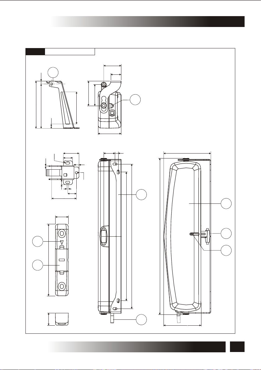
3.2- DENOMINATION OF THE COMPONENTS AND DIMENSIONS
Fig.2
Dimensions in mm
3
6.5
103
96.5
9.5
37
22
53
46
4
70
49
LEGEND:
1) Semi-automatic coupling
2) Slot side indicator
3) Bracket for bottom hung opening
4) Opening stroke adjustment
switch I=200 mm; II=380 mm
5) Connection bracket to the frame
6) Actuator
7) Chain adjustment end
8) Chain end adjustment screw
9) Power supply cable
34.12
20
Ø5
1.5
11
11
Ø5
4
19
54
24 7
101
5
6
16
310
2
276
335.2
7
8
86
1
15
9
80
VER.1.0
REV.07.04
INSTALLATION AND USE ISTRUCTIONS
7
3- TECHNICAL DESCRIPTION
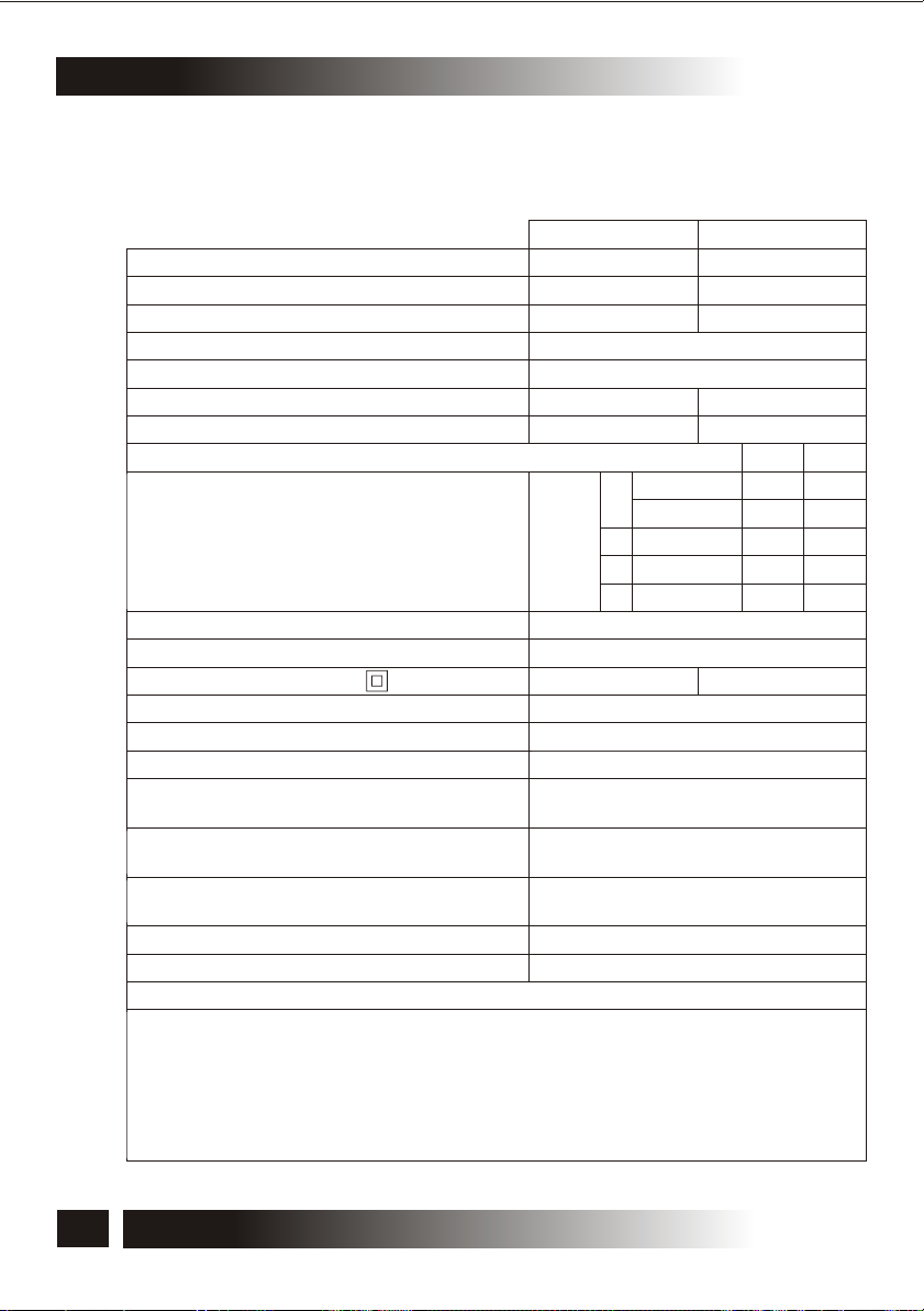
3.3- TECHNICAL DATA
Tab.1 contains the technical data characterising the actuators.
Power supply voltage
Absorbed current
Absorbed power with load
Maximum applicable thrust load
Maximum applicable tractive load
Idle translation speed
Duration of maximum idle stroke
End of stroke selected at mm
Minimum height H (mm)
of the window frame
Minimum window frame height
End of stroke selectable at
Double electric insulation
Type of service
(4)
S
2
Operating temperature
Protection degree of electric devices
Adjustment of the window frame connection
Parallel electric connection of more
actuators on the same window
Parallel electric connection of more
actuators on different windows
Actuator weight with brackets
Gross weight
Electronics with warning horn to signal to the user the wrong assembling
(1)
For the assembly position of the brackets see FIG.6
(2)
Distance of the actuator from the window frame opening hinge
(3)
Tolerance on the tripping precision of the limit switch at output: +/- 10 mm
(4)
Service of limited duration according to EN 60034
(5)
The “buzzer” device enables automatically itself emitting a continuous “beep” as long as the actuator
is supplied. For further details on the operation see par.5.6
(2)
(3)
Tab.1
C30/230V C30/24V
230 V ~ 50 Hz
24 V DC
0,22 A
50 W
300 N
300 N
24 mm/s
19 mm/s
16 s
0
1
brackets
2
3
Top hung
Bottom hung
Top hung
Top hung
Bottom hung
(1)
Position
assembly
H= 500 900 mm¸
200 380 mm¸
Yes
4 min
-5°C +55°C
IP 30
0 22 mm (Top hung)
¸
0 30 mm (Bottom hung)
¸
Only with proper
electronic device
Yes
(see wiring diagram)
1,1 kg
1,3 kg
(5)
1,3 A
35 W
20 s
200
250
500
250
350
400
C30
380
400
1000
400
500
950
/
INSTALLATION AND USE ISTRUCTIONS
8
VER.1.0
REV.07.04
C30
TECHNICAL DESCRIPTION -3
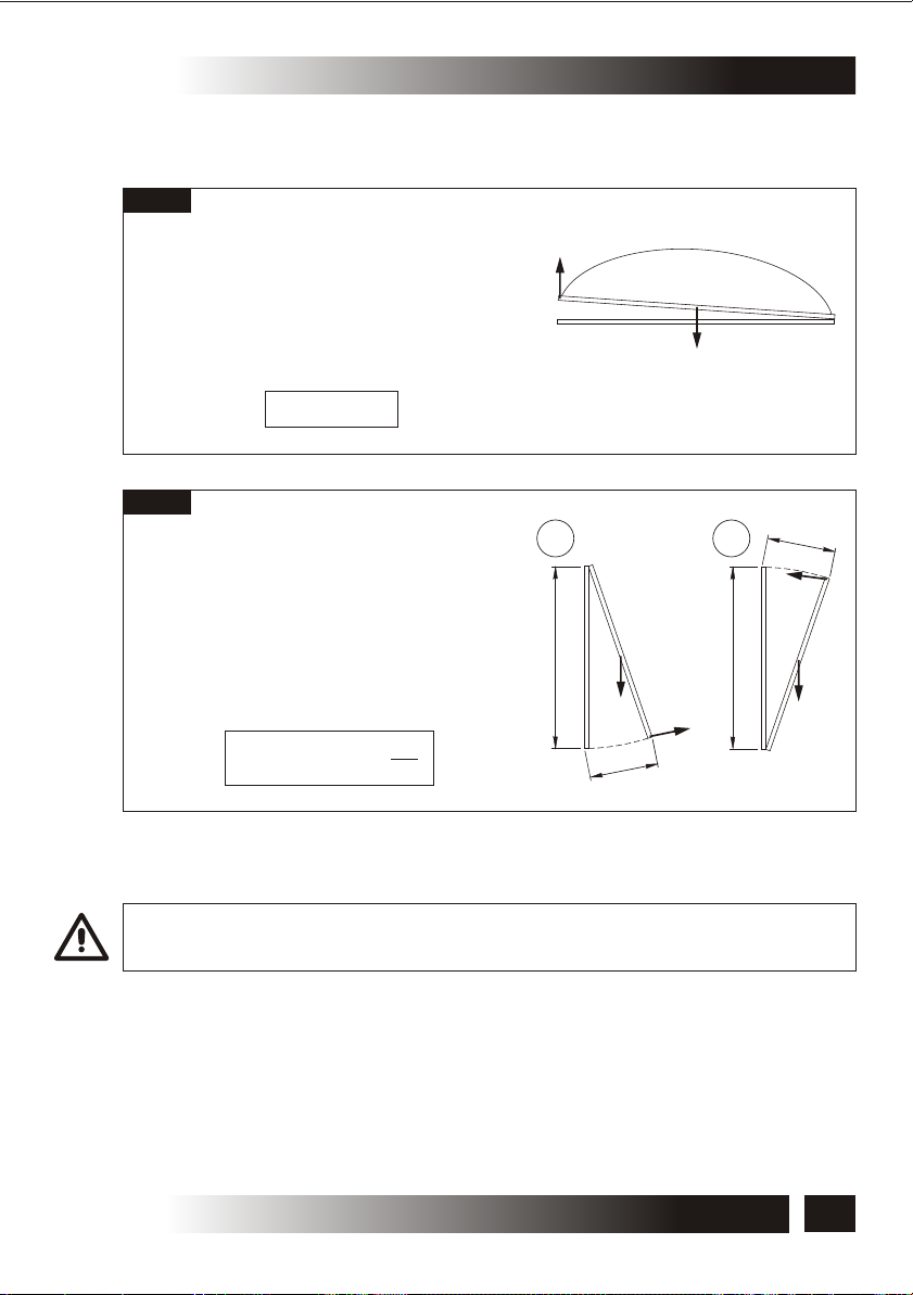
3.4- FORMULAS FOR THE CALCULATION OF THRUST AND TRACTIVE
FORCE
Fig.3
Horizontal domes or skylights
F= Force necessary for opening or
closing
P= Weight of the skylight or dome
(Only movable part)
F = 0,54 x P
Fig.4
Top hung windows (A) or
bottom hung windows (B)
F = Force necessary for opening or
closing
P = Weight of the window
(only movable part)
C = Window opening stroke
H = Window height
F = (0,54 x P) x ( )
C
H
F
A
H
P
C
3.5- DESTINATION OF USE
P
B
H
F
C
F
P
THE ACTUATOR HAS BEEN DESIGNED AND MANUFACTURED TO PERFORM
AUTOMATICALLY, BY MEANS OF A CONTROL DEVICE, THE OPENING AND CLOSING OF
TOP HUNG WINDOWS, BOTTOM HUNG WINDOWS, PIVOT WINDOWS, AND SKYLIGHTS.
VER.1.0
REV.07.04
INSTALLATION AND USE ISTRUCTIONS
9

3- TECHNICAL DESCRIPTION
3.6- USE LIMITS
The actuator has been designed and manufactured exclusively for the destination of
use given in par.3.5, therefore, any other type of use is strictly forbidden in order to
assure in any moment the safety of the installer and of the user, as well as the efficiency
of the actuator itself.
IT IS STRICTLY FORBIDDEN TO USE THE ACTUATOR FOR IMPROPER USES OTHER
THAN THE ONE FORESEEN BY THE MANUFACTURER (SEE PAR.3.5).
IT IS STRICTLY FORBIDDEN TO INSTALL THE ACTUATOR ON THE EXTERNAL SIDE OF
THE WINDOW FRAME SUBJECT TO ATMOSPHERIC AGENTS (RAIN, SNOW, ETC.).
THE USE OF THE ACTUATOR IN ENVIRONMENTS WITH POTENTIALLY EXPLOSIVE
ATMOSPHERE IS STRICTLY FORBIDDEN.
EX
IT IS COMPULSORY TO KEEP THE PACKAGE AND THE ACTUATOR OUT OF REACH OF
CHILDREN.
STANDARD
3.7- PACKAGE
Each standard package of the product (cardboard box) contains (Fig.5):
No.1 Actuator equipped with power supply cable;
No.1 Window frame connection bracket (Ref.A);
No.1 Bracket for bottom hung opening (Ref.B);
No.1 Small parts package (semi-automatic coupling, No.2 bracket lateral fastening
screws, No.7 screws AF Ø 4.2 x 19 mm to fasten the bracket to the window
frame, No.2 screws AF Ø 4.2 x 19 mm to fasten the semi-automatic coupling)
(Ref.C);
No.1 Installation and use instructions (Ref.D).
C30
MAKE SURE THAT THE ABOVE DESCRIBED COMPONENTS ARE CONTAINED IN THE
PACKAGE, AS WELL AS THAT THE ACTUATOR HAS NOT BEEN DAMAGED DURING
TRANSPORT.
SHOULD ANY ANOMALY BE DETECTED, IT IS FORBIDDEN TO INSTALL THE ACTUATOR,
AND IT IS COMPULSORY TO REQUIRE TECHNICAL ASSISTANCE FROM YOUR DEALER
OR THE MANUFACTURER.
THE PACKAGING (PAPER, PLASTIC, ETC.) HAS TO BE DISPOSED ACCORDING TO THE
LAWS IN FORCE.
10
INSTALLATION AND USE ISTRUCTIONS
VER.1.0
REV.07.04

C30
TECHNICAL DESCRIPTION -3
Fig.5
A
VER.1.0
REV.07.04
B
INST
ALLA
TION
AND USE INSTRUCT
CHAIN ACTUAT
WINDOW A
UTOM
OR FOR
ATIO
PATENTED
COMPULSORY FO
BEFORE
AND UN
INSTALLING AN
THIS MANUAL IS INTEGRAL PART OF TH
DERSTA
AND MUST BE PRESERVED FOR FUTURE REFEREN
R THE INSTALLE
ND THIS MANUAL
D USING THE AC
UNTIL DEMOLITION OF THE SAME.
R AND T
IN ALL ITS PART
VER. 1.0
P/N 0P52
TUATOR, IT IS
HE USER TO READ
00
REV. 06
E ACTUATOR
S.
.04
CE
INSTALLATION AND USE ISTRUCTIONS
IONS
N
C30
C
D
11

4- SAFETY
4.1- PROTECTION AGAINST ELECTRIC HAZARD
The actuator is protected against electric hazard due to direct and indirect contacts.
The protection measures against direct contacts aim at protecting people against
hazards due to contact with active parts, usually live parts; while the protection
measures against indirect contacts aim at protecting people against hazards due to
conducing part, which are usually insulated, but could become live in case of failure
(insulation failure).
The adopted protection measures are the following:
1) Insulation of live parts by means of a plastic material body;
2) Enclosure with suitable protection degree;
3) Only for mod.C30/230V equipped with double insulation: Protection of passive
type given by the use of components with double insulation, also called components
of class II or with equivalent insulation (
earthing system of the actuators equipped with double insulation
it is forbidden to perform the connection to the
).
4.2- RESIDUAL RISKS
The actuator does not have residual risks. The installer and the user are herewith
informed that after the actuator has been installed on the window, the actuator drive can
accidentally generate the following residual risk:
Residual risk:
Hazard of squashing or dragging of body parts inserted between the movable and the
fix part of the window frame.
C30
Exposure frequency:
Accidental and when the installer or the user decides to perform a wrong voluntary
action.
Severity of the damage:
Light lesions (usually reversible).
Adopted measures:
Before enabling the device, it is compulsory to verify that near the window there are not
persons, animals or things whose safety may be accidentally jeopardized. During
actuator operation, it is compulsory to be in a safe control position assuring visual
control on the window movement.
12
INSTALLATION AND USE ISTRUCTIONS
VER.1.0
REV.07.04
C30
INSTALLATION -5
5.1- GENERAL INSTRUCTIONS
THE ACTUATOR INSTALLATION CAN BE PERFORMED EXCLUSIVELY BY COMPETENT
AND QUALIFIED TECHNICAL PERSONNEL SATISFYING THE PROFESSIONAL AND
TECHNICAL REQUIREMENTS FORESEEN BY THE LAWS IN FORCE IN THE COUNTRY OF
INSTALLATION.
THE ACTUATOR PERFORMANCE MUST BE SUFFICIENT TO ASSURE THE CORRECT
MOVEMENT OF THE WINDOW. IT IS COMPULSORY TO VERIFY THE THRUST OR
TRACTIVE FORCE ACCORDING TO THE TYPE AND WEIGHT OF THE WINDOW (PAR. 3.4).
IT IS FORBIDDEN TO EXCEED THE LIMITS GIVEN IN TAB.1 CONCERNING THE
TECHNICAL DATA (PAR.3.3).
THE ACTUATOR INSTALLATION MUST BE PERFORMED EXCLUSIVELY WITH CLOSED
WINDOW OR SKYLIGHT.
BEFORE PERFORMING THE INSTALLATION OF THE ACTUATOR ON HOPPER
WINDOWS, VERIFY THAT ON BOTH SIDES OF THE WINDOW TWO COMPASS STROKE
LIMIT DEVICES ARE INSTALLED IN ORDER TO AVOID THE ACCIDENTAL FALL OF THE
WINDOW.
FOR CORRECT OPERATION OF THE ACTUATOR, THE WINDOW MUST HAVE A MINIMUM
HEIGHT OF 500 mm (DISTANCE OF THE ACTUATOR FROM THE WINDOW OPENING
HINGE).
VERIFY THAT THE DISTANCE "D" BETWEEN THE WINDOW FRAME (ON WHICH THE
FIXING OF THE ACTUATOR IS FORESEEN) AND THE WINDOW FRAME WING (ON WHICH
THE BRACKET FIXING IS FORESEEN) IS INCLUDED WITHIN 0 mm AND 30 mm, FOR THE
TOP HUNG ASSEMBLY (SEE FIG.6a), AND WITHIN 0 mm AND 22 mm FOR THE BOTTOM
HUNG ASSEMBLY (SEE FIG.6b).
VER.1.0
REV.07.04
INSTALLATION AND USE ISTRUCTIONS
13

5- INSTALLATION
C30
Fig.6a
THE POSITIONS 1 - 2 - 3 - 0 ARE TO BE USED ACCORDING
TO THE OVERLAPPED PART OF THE WINDOW
OVERLAPPED
D
PART
0 15 mm¸
15 22,5 mm¸
22,5 30 mm¸
THE FASTENING POSITION HAS TO BE VERIFIED AND EVALUATED ACCORDING
A
ACTUATOR
POSITION
0
2
TYPE OF
APPLICATION
TOP HUNG
TO THE PROFILE/LENGTH OF THE WING/FRAME AND OF THE WINDOW LIGHT.
FOR WINDOWS HAVING A “WINDOW LIGHT” LOWER THAN 500 mm, IT IS
SUGGESTED TO ADJUST THE STROKE 200 mm (SWITCH POS.I).
D
DIMENSION "D" VARIABLE BETWEEN 0 TO 30 mm
101
37
14
Wing
10 (+/- 1)
A
22
4
15
6
Frame
(Standard “0” Pos.)
INSTALLATION AND USE ISTRUCTIONS
7.5
7.5
7.5
0
2
53
3
REV.07.04
49
VER.1.0

C30
INSTALLATION -5
Fig.6b
THE POSITIONS 1 - 2 - 3 - 0 ARE TO BE USED ACCORDING
TO THE OVERLAPPED PART OF THE WINDOW
0 mm¸ 15
0 5 mm (+7,5)¸ 1
THE DIMENSION IS INCLUDED BETWEEN 96 AND 118
THE FASTENING POSITION HAS TO BE VERIFIED AND EVALUATED ACCORDING
C
A
0 3 0
3
BOTTOM HUNG
(see Fig.30)
BOTTOM HUNG
(see Fig.31)
TO THE PROFILE/LENGTH OF THE WING/FRAME AND OF THE WINDOW LIGHT.
55 00
55 33
D
DIMENSION "D" VARIABLE
BETWEEN 0 TO 15 mm
99
5555
8855
77
11
Frame
A
3300
33
C
2
0
3
B
3377
VER.1.0
REV.07.04
STROKE
200 mm
380 mm
44
2200. . 55
Wing
MIN. WINDOW LIGHT
500 mm
900 mm
INSTALLATION AND USE ISTRUCTIONS
OPENING ANGLE
22°
24.5°
77..55
MOTOR OVERALL
DIMENSIONS (B)
39.5 mm
41.5 mm
5544
15
5- INSTALLATION
C30
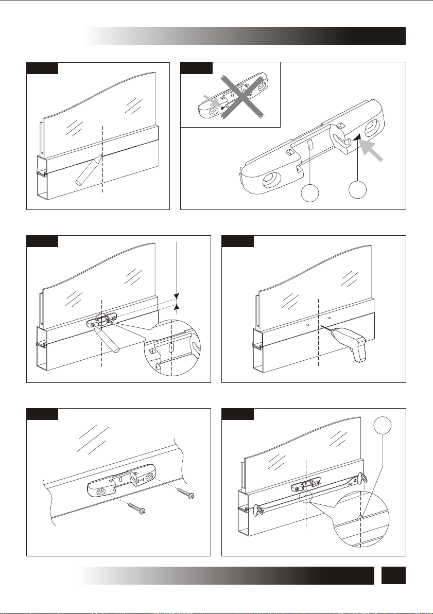
5.2- TOP HUNG WINDOWS
Fig.7
(Fig. 7 and Fig. 13, 24)
1) Open the package (par. 3.7) and extract the
various components;
2) Fig.13- With a pencil draw the centre line “X” of the
window frame;
3) Fig.14- Align to the centre line the semi-automatic
coupling using as reference the rib (Ref.1) located
in the middle of the same with the indicator on the
quick release side on the right (Ref.2);
4) Fig.15- Place the semi-automatic coupling at a
minimum height of 10 mm from the frame and mark the drilling points;
5) Fig.16/17- Using a suitable drill, perform on the wing two holes of Ø 3.7 and tighten
the semi-automatic coupling with the suitable screws;
6) Fig.18- Align to the centre line the window frame connection bracket using as
reference the indicator of the centre line (Ref.1) located in the middle of the same;
7) Place the bracket on the frame at such a height as to align the axis of the bracket
fastening seat with the axis of the semi-automatic coupling fastening holes, as shown
in Fig.19 and mark the drilling points;
8) Fig.20/21- With a suitable drill perform four holes of Ø 3.7 on the frame and fasten the
bracket with the suitable screws;
VERIFY THAT THE CHAIN ADJUSTMENT END (FIG.8-Ref.A) IS ON THE SAME AXIS OF
THE SEMI-AUTOMATIC COUPLING (FIG.8-Ref.B). OTHERWISE, REPEAT THE
PROCEDURES AND POSITION THEM CORRECTLY. IF THE TWO ELEMENTS ARE NOT
COAXIAL, THIS MAY DAMAGE THE ACTUATOR AND WINDOW FRAME (FIG.8).
16
Fig.8
NO
A A
INSTALLATION AND USE ISTRUCTIONS
B
YES
B
VER.1.0
REV.07.04
C30
INSTALLATION -5
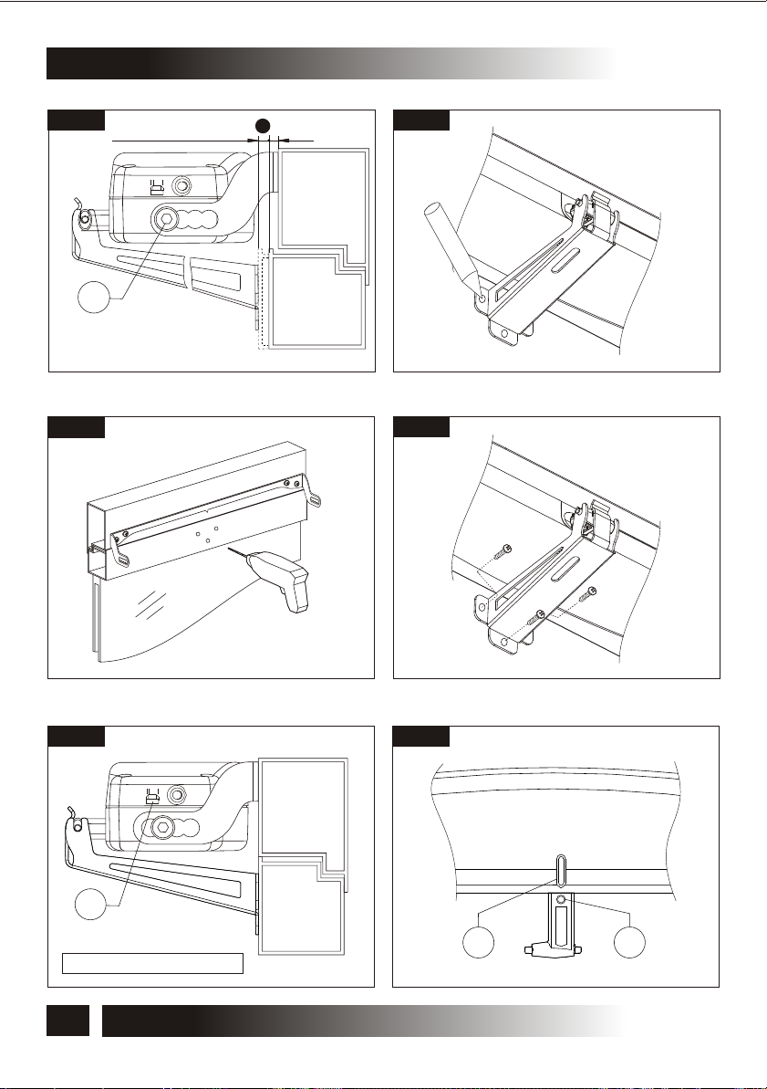
9) Fig.22- Loosen the chain end adjustment screw (Ref.3) and connect the actuator to
the semi-automatic coupling inserting the chain adjustment end first of all in the left
connection point (Ref.1) and then in the right connection point (Ref.2);
10) Fig.23- Using the two supplied screws (Ref.1) tighten the actuator to the window
frame connection bracket in the most suitable position according to the value of the
overlapped part “D” (see Fig.6) and tighten the chain end adjustment screw (Fig.22-
Ref.3);
11) Fig.24- Adjust the opening stroke by means of the switch (Ref.1) located in the right
side of the actuator according to the wing opening:
12) Perform the electric connection according to the provisions of par.5.4 and referring
to the wiring diagram.
THE SELECTION OF THE STROKE MUST BE PERFORMED WITH SWITCHED OFF
ACTUATOR EXCLUSIVELY BY COMPETENT AND QUALIFIED TECHNICAL PERSONNEL.
CAUTION: VERIFY THAT THE SELECTED STROKE IS SOME CENTIMETRES LOWER
THAN THE STROKE EFFECTIVELY ALLOWED BY MECHANICAL LOCKS, COMPASS
LIMIT DEVICES OR WING OPENING HINDRANCES.
FOR A CORRECT ADJUSTMENT OF THE WINDOW FRAME CLOSING SEE THE
INDICATIONS GIVEN IN PAR. 5.6.
5.3- BOTTOM HUNG WINDOWS
Fig.9
(Fig.9 and 25÷35)
1) Open the package (par.3.7) and extract the
various components;
2) Fig. 25- With a pencil draw the centre line “Y” of
the window frame;
3) Fig. 26- Align to the centre line the window frame
connection bracket using as reference the centre
line indicator (Ref.1) located in the middle of the
same, then mark the drilling points on the frame;
4) Fig.27/28- With a suitable drill, perform four holes
of Ø 3.7 on the frame and tighten the bracket with the suitable screws;
5) Fig.29- Using the two supplied screws (Ref.1) tighten the actuator to the window
frame connection bracket in the position “0” (see Fig.6);
6) Fig. 29/30- Tighten the actuator to the bracket with the suitable screws (Fig.29Ref.2). Connect the bracket for the bottom hung opening to the chain end and
unscrew the adjustment screw of the same (Fig 29-Ref 2);
7) Fig.30/32- Select the position of the actuator with reference to the window frame
connection bracket (see Fig.6). Lean the bracket on the wing, adjust the length of the
chain end and tighten the adjustment screw. Mark the drilling points;
VER.1.0
REV.07.04
INSTALLATION AND USE ISTRUCTIONS
17

5- INSTALLATION
8) Fig.33/34- With a suitable drill, perform 3 holes of Ø 3.7 on the wing and tighten the
bracket with the suitable screws;
9) Fig.35- Adjust the opening stroke by means of the switch (Ref.1) located in the right
side of the actuator according to the wing opening;
10) Perform the electric connection according to the provisions of par.5.4 and referring
to the wiring diagram.
THE SELECTION OF THE STROKE MUST BE PERFORMED WITH SWITCHED OFF
ACTUATOR EXCLUSIVELY BY COMPETENT AND QUALIFIED TECHNICAL PERSONNEL.
CAUTION: VERIFY THAT THE SELECTED STROKE IS SOME CENTIMETRES LOWER
THAN THE STROKE EFFECTIVELY ALLOWED BY MECHANICAL LOCKS, COMPASS
LIMIT DEVICES OR WING OPENING HINDRANCES.
FOR A CORRECT ADJUSTMENT OF THE WINDOW FRAME CLOSING SEE THE
INDICATIONS GIVEN IN PAR. 5.6.
C30
18
INSTALLATION AND USE ISTRUCTIONS
VER.1.0
REV.07.04

C30
INSTALLATION -5
5.4- ELECTRIC CONNECTIONS (Wiring diagram)
THE ELECTRIC CONNECTION OF THE ACTUATOR CAN BE PERFORMED ONLY BY
COMPETENT AND QUALIFIED TECHNICAL PERSONNEL SATISFYING THE TECHNICAL
AND PROFESSIONAL REQUIREMENTS FORESEEN BY THE LAW IN FORCE IN THE
COUNTRY OF INSTALLATION ISSUING TO THE CUSTOMER A DECLARATION OF
CONFORMITY FOR THE CONNECTION AND/OR THE PLANT PERFORMED.
BEFORE PERFORMING THE ELECTRIC CONNECTION OF THE ACTUATOR, VERIFY THE
CORRECT INSTALLATION ON THE WINDOW.
THE MAINS TO WHICH THE ACTUATOR IS CONNECTED MUST COMPLY WITH THE
REQUIREMENTS OF THE LAWS IN FORCE IN THE COUNTRY OF INSTALLATION, AS
WELL AS SATISFY THE TECHNICAL FEATURES GIVEN IN TAB.1 AND ON THE RATING
PLATE AND THE "CE" MARKING (PAR.3.1), AS WELL AS BE EQUIPPED WITH A
SUITABLE "EARTHING PLANT".
THE SECTION OF THE MAINS CABLES MUST BE PROPERLY SIZED ACCORDING TO THE
ABSORBED ELECTRIC POWER (SEE RATING PLATE AND "CE" MARKING).
ANY TYPE OF ELECTRIC MATERIAL (PLUG, CABLE, TERMINALS, ETC.) USED FOR THE
CONNECTION MUST BE SUITABLE FOR THE USE, WITH "CE" MARKING AND
COMPLYING WITH THE REQUIREMENTS FORESEEN BY THE LAWS IN FORCE IN THE
COUNTRY OF INSTALLATION.
IT IS COMPULSORY TO INSTALL UPSTREAM OF THE MAINS A SECTIONING DEVICE
WITH A 30 mA DIFFERENTIAL PROTECTION, ASSOCIATED WITH THE EARTHING PLANT.
TO ASSURE A CORRECT SEPARATION FROM THE MAINS, IT IS COMPULSORY TO
INSTALL UPSTREAM OF THE DEVICE A BIPOLAR TEMPORARY SWITCH (PUSHBUTTON) OF APPROVED TYPE. UPSTREAM OF THE CONTROL LINE, IT IS
COMPULSORY TO INSTALL AN UNIPOLAR CUTOUT SWITCH WITH CONTACT OPENING
OF AT LEAST 3 mm.
IT IS FORBIDDEN TO PERFORM THE CONNECTION TO THE EARTHING PLANT OF THE
ACTUATORS EQUIPPED WITH DOUBLE INSULATION (MOD. ACK42).
BEFORE PERFORMING THE ELECTRIC CONNECTION OF THE ACTUATOR, VERIFY
THAT THE POWER SUPPLY CABLE IS NOT DAMAGED. SHOULD IT BE DAMAGED, IT
MUST BE REPLACED BY THE MANUFACTURER OR BY THE TECHNICAL ASSISTANCE
SERVICE OR IN ANY CASE BY AUTHORIZED OPERATORS.
5.5- CONTROL DEVICES
THE CONTROL DEVICES USED TO DRIVE THE ACTUATOR MUST ASSURE THE SAFETY
CONDITIONS FORESEEN BY THE LAWS IN FORCE IN THE COUNTRY OF USE.
According to the different type of installations, the actuators can be driven by the
following control devices:
VER.1.0
REV.07.04
INSTALLATION AND USE ISTRUCTIONS
19

5- INSTALLATION
1) MANUAL PUSH-BUTTON:
Open/closed electric switch (I-0) controlling the single actuator or more than one
actuator simultaneously;
2) CONTROL AND FEEDING UNIT:
Microprocessor control units (e.g.: Mod. TF, EVP, etc.) controlling the single actuator
or more than one actuator simultaneously by means of one or more manual pushbuttons, an infrared remote control or a 433 Mhz radio control.
To these control units, it is possible to connect the rain sensors (RPR - 12V), the wind
sensor (RW) and the brightness sensor (RL);
THE EVENTUALLY USED UNITS MUST SUPPLY A VOLTAGE TO C30 FOR MAX. 120 s.
3) SYNCHRONIZATION UNIT:
Microprocessor control unit (e.g.: Mod. USA2) controlling by means of a manual
push-button the simultaneous operation of 2 or 3 actuators installed on a single
window assuring the regular opening and closing movement.
5.6- ADJUSTMENT OF THE WINDOW FRAME CLOSING (Fig.24-34)
THE CORRECT ADJUSTMENT OF THE WINDOW FRAME CLOSING ASSURES THE LIFE
AND THE TIGHTNESS OF THE SEALS, AS WELL AS THE GOOD OPERATION OF THE
ACTUATOR.
C30
A good method to perform a correct assembly, consists in verifying that after the
disabling of the gear motor the window seals are correctly compressed. Should this not
occur, adjust again the chain end by placing it back as needed and eventually by shifting
the actuator on the various positions offered by the bracket and then by adjusting the
chain end (see Tab. 1).
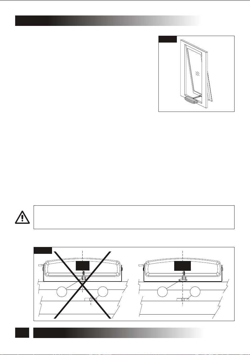
As shown in FIG.36, although the window is closed, the chain end adjustment screw
(Ref.2) is located outside the slit (Ref.1) located on the actuator body causing therefore
the failed tripping of the limit switch related to the chain re-entering. In this case, the
actuator motor remains under maximum stress conditions until the electronic protection
tripping and the “BUZZER” enabling.
This acoustic warning device emits a continuous “beep” until the actuator is
connected to the power supply.
20
INSTALLATION AND USE ISTRUCTIONS
VER.1.0
REV.07.04

C30
CONSIDERING THAT THIS ADDITIONAL SAFETY DEVICE HAS BEEN DEVELOPED IN
ORDER TO OFFER A RAPID SYSTEM TO DETECT ANY EVENTUAL ANOMALY IN THE
ASSEMBLY OF THE DEVICE, FOR A CORRECT INSTALLATION OF THE PRODUCT IT IS
COMPULSORY TO FOLLOW ALL THE ASSEMBLING PROCEDURES DESCRIBED IN THIS
MANUAL.
INSTALLATION -5
5.7- EMERGENCY PROCEDURES
Should it be necessary to open the window manually due to power supply failure or
mechanism block, follow these instructions:
BEFORE PERFORMING ANY TYPE OF INTERVENTION ON THE ACTUATOR AND ON THE
WINDOW, IT IS COMPULSORY TO DISCONNECT THE POWER SUPPLY OF THE
ACTUATOR AND TO PUT ON "0" THE EVENTUAL SWITCHES OF THE CONTROL
DEVICES.
IT IS COMPULSORY TO PADLOCK THE MAIN SWITCH OF THE DISCONNECTION DEVICE
INSTALLED ON THE MAINS IN ORDER TO AVOID ANY UNEXPECTED START. IF THE MAIN
SWITCH CANNOT BE PADLOCKED, IT IS COMPULSORY TO PLACE A SIGN FORBIDDING
THE ENABLING.
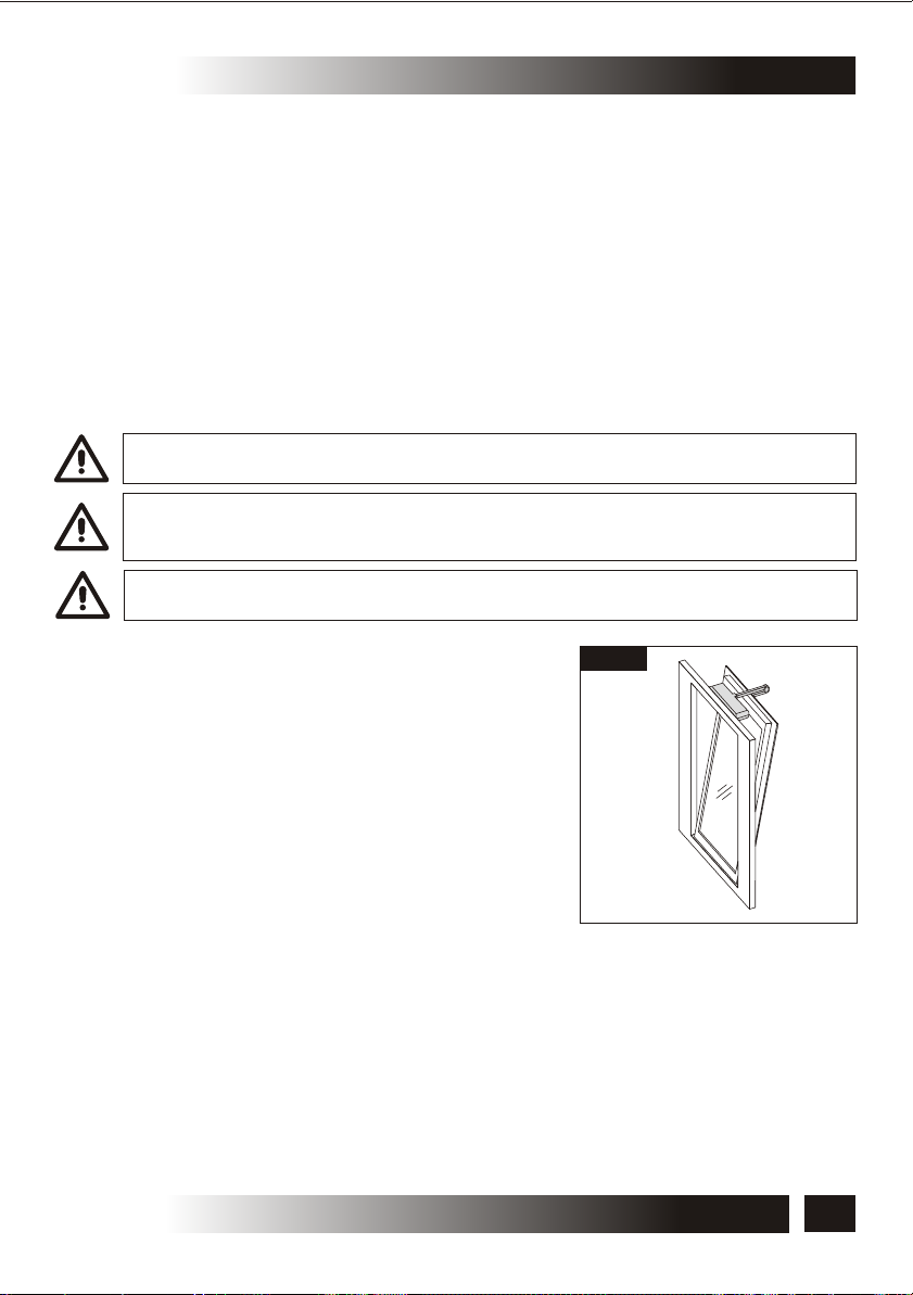
• Top hung opening: Fig.10- insert a screwdriver vertically in the right lateral opening
(Ref.1) of the semi-automatic coupling and lever on the reed holding the chain end
(Fig.10) and extract the actuator.
• Bottom hung opening: Fig.11- unscrew the fastening screws of the actuator from the
window frame connection bracket and extract the actuator.
Fig.10
VER.1.0
REV.07.04
Fig.11
1
INSTALLATION AND USE ISTRUCTIONS
21
6- USE AND OPERATION
6.1- USE OF THE ACTUATOR
THE ACTUATOR CAN BE USED ONLY BY A USER ACTING IN COMPLIANCE WITH THE
INSTRUCTIONS GIVEN IN THIS MANUAL AND/OR IN THE MANUAL OF THE ACTUATOR
COMMAND DEVICE (e.g.: WIND AND RAIN CONTROL UNIT).
BEFORE USING THE ACTUATOR, IT IS COMPULSORY FOR THE USER TO READ AND
UNDERSTAND IN ALL ITS PARTS THIS MANUAL, AS WELL AS THE EVENTUAL MANUAL
OF THE INSTALLED CONTROL DEVICE TYPE.
BEFORE OPERATING THE ACTUATOR, THE USER MUST COMPULSORILY VERIFY THAT
NEAR AND/OR UNDER THE WINDOW THERE ARE NOT ANY PERSON, ANIMAL AND
THING WHOSE SAFETY MAY BE ACCIDENTALLY JEOPARDISED (SEE PAR. 4.2).
DURING THE OPERATION OF THE ACTUATOR CONTROL DEVICE, THE USER HAS TO
COMPULSORILY OCCUPY A CONTROL POSITION ASSURING VISUAL CONTROL ON THE
WINDOW MOVEMENT.
THE FUNCTION EFFICIENCY AND THE RATED PERFORMANCE OF THE ACTUATOR, OF
THE WINDOW FRAME ON WHICH IT IS INSTALLED AND OF THE ELECTRIC EQUIPMENT
MUST BE VERIFIED STEADILY IN TIME BY PERFORMING, WHEN NECESSARY,
INTERVENTIONS OF ROUTINE AND SUPPLEMENTARY MAINTENANCE ASSURING THE
OPERATION CONDITIONS IN COMPLIANCE WITH THE SAFETY REGULATIONS.
ALL ABOVE MENTIONED MAINTENANCE INTERVENTIONS MAY BE PERFORMED
EXCLUSIVELY BY TECHNICAL COMPETENT AND QUALIFIED TECHNICAL PERSONNEL
SATISFYING THE TECHNICAL AND PROFESSIONAL REQUIREMENTS FORESEEN BY
THE LAW IN FORCE IN THE COUNTRY OF INSTALLATION.
C30
The use of the actuator allows to control automatically the opening and closing of
the window according to the type of control device installed (see par. 5.5).
22
INSTALLATION AND USE ISTRUCTIONS
VER.1.0
REV.07.04

C30
7.1- GENERAL INSTRUCTIONS
THE DEMOLITION OF THE ACTUATOR MUST OCCUR IN COMPLIANCE WITH THE LAWS
IN FORCE ON ENVIRONMENT PROTECTION.
DIFFERENTIATE THE PARTS MAKING UP THE ACTUATOR ACCORDING TO THEIR
DIFFERENT MATERIAL TYPE (PLASTIC, ALUMINIUM, ETC.).
DEMOLITION -7
C30
SPARE PARTS AND ACCESSORIES UPON REQUEST -8
8.1- GENERAL INSTRUCTIONS
THE USE OF "NON-ORIGINAL" SPARE PARTS AND ACCESSORIES WHICH MAY
ENDANGER THE SAFETY AND THE EFFICIENCY OF THE ACTUATOR IS FORBIDDEN.
THIS ACTION SHALL INVOLVE THE WARRANTY EXPIRATION.
ORIGINAL SPARE PARTS AND ACCESSORIES HAVE TO BE REQUESTED EXCLUSIVELY
TO YOUR DEALER OR TO THE MANUFACTURER STATING TYPE, MODEL, SERIAL
NUMBER, AND YEAR OF CONSTRUCTION OF THE ACTUATOR.
VER.1.0
REV.07.04
INSTALLATION AND USE ISTRUCTIONS
23

8- SPARE PARTS AND ACCESSORIES UPON REQUEST
Fig.12
DOME ASSEMBLY BRACKET
C30
FOR A CORRECT OPERATION OF THE ACTUATOR, “D” MUST HAVE A VALUE INCLUDED
BETWEEN 0 mm AND 30 mm.
24
INSTALLATION AND USE ISTRUCTIONS
VER.1.0
REV.07.04
C30
INSTALLATION ON TOP HUNG WINDOWS
Fig.13
Fig.15
Fig.14
SX
X
DX
1
Fig.16
X
H=10±1mm
X
2
Fig.17 Fig.18
VER.1.0
REV.07.04
INSTALLATION AND USE ISTRUCTIONS
1
X
25

INSTALLATION ON TOP HUNG WINDOWS
C30
Fig.19
Wing
Fig.21
Frame
Fig.20
Fig.22
X
1
2
DXSX
3
DX
Fig.23
26
Fig.24
1
INSTALLATION AND USE ISTRUCTIONS
1
I= 200 mm II= 380 mm
VER.1.0
REV.07.04

C30
INSTALLATION ON BOTTOM HUNG WINDOWS
Fig.25
Fig.27
Fig.26
H=30±1mm
Y
Y
1
Fig.28
H=30±1mm
Fig.29
1
VER.1.0
REV.07.04
Fig.30
DIMENSIONS “D”
VARIABLE FROM
0 mm TO 15 mm
D
Telaio
Wing
2
INSTALLATION AND USE ISTRUCTIONS
0
27
INSTALLATION ON BOTTOM HUNG WINDOWS
Fig.34
Fig.31 Fig.32
DIMENSIONS “D” VARIABLE
FROM 0 mm TO 15 mm
D
7.5 mm
Frame
C30
Fig.33
Fig.35
3
Wing
Fig.34
Fig.36
Telaio
1
I= 200 mm II= 380 mm
28
INSTALLATION AND USE ISTRUCTIONS
Wing
1 2
VER.1.0
REV.07.04

C30
Wiring diagram
L
N
DRAWINGS FOR INSTALLATION
L
N
CLOSES
230V~50Hz
C30 C30
BROWN
GREY
BLACK
230 V24 V
24V
CLOSES
OPENS
IT IS FORBIDDEN TO PERFORM THE CONNECTION TO THE
EARTHING SYSTEM OF THE ACTUATORS EQUIPPED WITH
DOUBLE INSULATION.
(LIGHT BLUE)
OPENS
CLOSES
230V~50Hz
GREY
BLACK
BROWN
C30
CLOSES
24V
OPENS
(LIGHT BLUE)
OPENS
VER.1.0
REV.07.04
C30
BLUE
(BLACK)
IT IS COMPULSORY TO INSTALL UPSTREAM OF THE MAINS A
SECTIONING DEVICE WITH 30 mA DIFFERENTIAL
PROTECTION, ASSOCIATED TO THE EARTHING SYSTEM.
C30
BLUE
(BLACK)
(RED)
BROWN
C30
INSTALLATION AND USE ISTRUCTIONS
(RED)
BROWN
29

REMARKS
C30
30
INSTALLATION AND USE ISTRUCTIONS
VER.1.0
REV.07.04

C30
CERTIFICATE OF GUARANTEE
The warranty for the products, and their single parts, defective for poor materials or manufacturing
defects is extended for a period of 24 months from the date of dispatch by the manufacturer.
The manufacturer provides that the products are reliable, which means that he undertakes to
repair or replace free of charge any of the parts proved to be defective in materials or
manufacturing during the warranty period, in the shortest possible time. The purchaser shall not
expect any refund for any damage due to improper installation or any other expenses. Such
warranty will not however apply to any particularly fragile parts, or to parts exposed to natural wear
as well as to corrosive operations and to current overloads (even if only temporary), etc. The
manufacturer shall not be considered liable against any damages due to improper installation,
manoeuvring or insertion, as well as to excessive solicitations or misuse.
The manufacturer shall not be liable if the product has been modified, dismantled, if the label is
missing or if it shows clear signs of collision or other. Repairs under guarantee are considered "ex
manufacturer's factory", which means that all the arising transport expenses (in- and outward) are
always to the purchaser charge. For any inspections by a skilled staff, cost of labour shall be to the
manufacturer charge. Displacement costs (in- and outward journey), journey hours, board and
lodging must, on the other hand, be refunded from the purchaser. Such warranty has validity
only if the present form, being part of the instructions manual, is duly filled in and the
damage cause is clearly described in the assistance report.
The products must be installed and used in compliance with the technical features and the
instructions given by TOPP, as well as according to the safety regulations and the standards that
rule the installation and employment of the electrical devices in the country where the products are
installed and used. For such reason, the purchaser expressly relieves TOPP from any
responsibility arising from improper use, from the inobservance of the safety regulations, of the
technical specifications as well as of the operating instructions.
VER.1.0
REV.07.04
MODEL
SERIAL No.
CUSTOMER
ADDRESS
RETAILER’S NAME (STAMP AND SIGNATURE)
INSTALLATION AND USE ISTRUCTIONS
TECHNICAL REPORT
31

TOPP SPA
Via Galvani, 59 - 36066 Sandrigo (VI) - Italia
Tel. +39 0444 656700 - Fax +39 0444 656701
Info@topp.it - www.topp.it
 Loading...