

IT
ISTRUZIONI PER L’INSTALLAZIONE E L'USO
EN
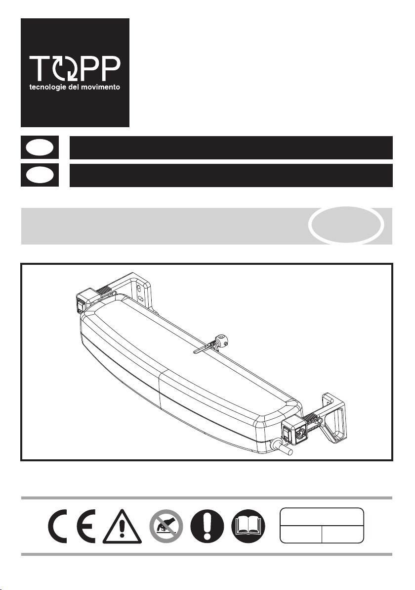
ATTUATORE A CATENA PER AUTOMAZIONE FINESTRE
BREVETTATO
INSTALLATION AND USE INSTRUCTIONS
CHAIN ACTUATOR FOR WINDOW AUTOMATION
C25
istruzioni originali / original instructions
COD. 0P5270
VER 0.0
REV 02.18


IT
IT
1- DICHIARAZIONE CE DI INCORPORAZIONE DI QUASI MACCHINA................................pag. 04
2- GENERALITÀ
2.1- Avvertenze generali ......................................................................................................pag. 05
2.2- Descrizione del personale ............................................................................................pag. 05
2.3- Assistenza tecnica ........................................................................................................pag. 05
3- DESCRIZIONE TECNICA
3.1- Targa dati e marcatura “CE” .........................................................................................pag. 05
3.2- Denominazione dei componenti e dimensioni ..............................................................pag. 06
3.3- Dati tecnici ....................................................................................................................pag. 06
3.4- Formule per il calcolo della forza di spinta o trazione...................................................pag. 07
3.5- Destinazione d’uso .......................................................................................................pag. 07
3.6- Confezione ...................................................................................................................pag. 07
4- SICUREZZA
4.1- Avvertenze generali......................................................................................................pag. 08
4.2- Dispositivi di protezione................................................................................................pag. 08
4.3- Targhe relative alla sicurezza .......................................................................................pag. 08
4.4- Rischi residui ................................................................................................................pag. 08
5- INSTALLAZIONE
5.1- Avvertenze generali......................................................................................................pag. 09
5.2- Finestre a sporgere.......................................................................................................pag. 09
5.3- Finestre a vasistas........................................................................................................pag. 10
5.4- Collegamento elettrico..................................................................................................pag. 10
5.5- Dispositivi di comando ..................................................................................................pag. 11
5.6- Regolazione della chiusura del serramento..................................................................pag. 11
5.7- Manovre di emergenza .................................................................................................pag. 11
INDICE
6- USO E FUNZIONAMENTO
6.1- Utilizzo dell’attuatore.....................................................................................................pag. 12
7- APPENDICI
7.1- Manutenzione ...............................................................................................................pag. 12
7.2- Demolizione..................................................................................................................pag. 12
7.3- Ricambi ed accessori a richiesta ..................................................................................pag. 12
8- FIGURE ...............................................................................................................................pag. 23
C25
IT
ISTRUZIONI PER L’INSTALLAZIONE E L’USO
3

IT
1
DICHIARAZIONE CE DI INCORPORAZIONE DI QUASI MACCHINA
ORIGINALE
Il sottoscritto in nome e per conto di
Topp S.r.l.
Via Galvani, 59
36066 Sandrigo (VI)
Italia
dichiara che la persona autorizzata a costituire il fascicolo tecnico è
Nome: Bettiati Roberto - Topp S.r.l.
Indirizzo: via Galvani,59 36066 Sandrigo (VI)
e che alla seguente quasi macchina
Tipo: C25
Modello/i: C25/230V
i seguenti requisiti essenziali della
Direttiva Macchine 2006/42/CE (incluse tutte le revisioni applicabili) Attuazione Italiana DLgs.27 gennaio 2010,
n.17
sono stati applicati e soddisfatti:
Allegato I: 1.5.1; 1.5.2; 1.5.10; 1.5.11
che la documentazione tecnica è preparata in conformità con l'Allegato VII, parte B della
summenzionata Direttiva Macchine.
La quasi-macchina sopra descritta è anche conforme alle seguenti altre direttive (incluse tutte le
revisioni applicabili):
Direttiva Compatibilità Elettromagnetica (EMC) 2014/30/UE:
Attuazione Italiana DLgs.18 maggio 2016, n.80
Direttiva RoHS II 2011/65/UE:
Attuazione Italiana DLgs. 4 marzo 2014, n.27
Sono state applicate le seguenti norme armonizzate:
EN 60335-2-103:2015 Parti applicabili
EN 55014-1:2006 + A1:2009 + A2:2011
EN 55014-2:2015
EN 61000-6-2:2005.
EN 61000-6-3:2007 + A1:2011 + AC:2012.
EN 50581:2012
e i seguenti documenti tecnici:
EN 62233:2008
Il sottoscritto, inoltre, si impegna, a fronte di una motivata richiesta da parte delle autorità nazionali di
sorveglianza del mercato, a trasmettere alle suddette autorità, in formato elettronico o cartaceo, tutta la
necessaria documentazione tecnica della quasi-macchina.
La quasi-macchina sopra descritta non deve essere messa in servizio fintantoché la macchina finale
nella quale è stata incorporata non è stata dichiarata conforme ai requisiti definiti dalla summenzionata
Direttiva Macchine.
La presente dichiarazione è rilasciata sotto la responsabilità esclusiva del fabbricante.
ATTUATORE A CATENA PER AUTOMAZIONE FINESTRE
Data: Sandrigo 01/02/2018 Firma: Matteo Cavalcante
Amministratore ................................................................
4
ISTRUZIONI PER L’INSTALLAZIONE E L’USO
IT
C25
IT
2
GENERALITÀ
AVVERTENZE GENERALI
2.1
Prima di installare e utilizzare l’attuatore è
obbligatorio che l’installatore e l’utilizzatore
leggano e comprendano in tutte le sue parti il
presente manuale.
& Il presente manuale è parte integrante dell’attuatore e
deve obbligatoriamente essere conservato per futuri
riferimenti.
& Il presente manuale è destinato al proprietario, agli
utilizzatori, agli installatori e ai tecnici abilitati alla
manutenzione dell’attuatore ed è pertanto opportuno
conservarlo, assieme a tutta la documentazione allegata,
in un luogo accessibile e noto a tutti gli operatori.
& Il presente manuale ha lo scopo di fornire tutte le
informazioni necessarie affinché, oltre ad un corretto
utilizzo dell’attuatore, sia possibile gestire lo stesso nel
modo più autonomo e sicuro possibile: TOPP srl declina
ogni responsabilità per eventuali danni a persone,
animali e cose causati dall’innosservanza delle norme qui
descritte.
& Il presente manuale è stato redatto da TOPP srl che
ne riserva tutti i diritti d’autore. Nessuna parte dello stesso
deve essere riprodotta o diffusa senza l’autorizzazione
scritta da parte del fabbricante.
& TOPP srl si riserva il diritto di modificare e migliorare il
manuale e i prodotti descritti in qualsiasi momento e
senza obbligo di preavviso.
& Per un corretto funzionamento dell'automazione, si
consiglia di effettuare una manutenzione periodica della
stessa, secondo quanto indicato al par.7.1 del presente
manuale.
& La garanzia dell'attuatore decade qualora l'impiego
dello stesso non sia conforme alle istruzioni e norme
descritte nel presente manuale e qualora vengano
utilizzati componenti, accessori, ricambi, centrali e
sistemi di comando/alimentazione non originali.
DESCRIZIONE DEL PERSONALE
2.2
Tecnico specializzato elettricista
Il tecnico specializzato deve essere in grado di installare
l’attuatore, di metterlo in opera e di operare in presenza di
tensione all'interno di armadi elettrici e scatole di
derivazione. E’ inoltre abilitato a tutti gli interventi di
natura elettrica e meccanica di regolazione e di
manutenzione.
L’installazione dell’attuatore deve essere pertanto
es eguita escl us ivament e da perso nale t ecnico
competente e qualificato in possesso dei requisiti tecnico
professionali previsti dalla legislazione vigente nel paese
di installazione.
L'installatore sarà l'unico soggetto responsabile per
l'errata installazione e per il mancato rispetto delle
istruzioni riportate nel presente manuale. L'installatore
risponderà pertanto in via esclusiva nei confronti
dell'utente e/o di terzi per tutti i danni a cose e/o persone
che dovessero derivare dall'errata installazione .
Utilizzatore
Personale in grado di comandare l’attuatore in
condizioni normali, attraverso l'uso dei comandi
preposti. Deve inoltre essere in grado di operare con
l’attuatore in “manutenzione” per effettuare operazioni
se mpl ici d i man ute nzi one ord ina ria ( pul izi a),
avviamento o ripristino dell’attuatore in seguito ad
un'eventuale sosta forzata.
Gli utilizzatori non devono eseguire operazioni riservate
ai manutentori o ai tecnici specializzati. Il costruttore non
risponde di danni derivati dalla mancata osservanza di
questo divieto.
L’utilizzo dell’attuatore deve essere esclusivamente
assegnato a utenti che agiscono in conformità delle
istruzioni riportate nel presente manuale e nei manuali
dei dispositivi TOPP ad esso collegati (es. unità di
alimentazione).
ASSISTENZA TECNICA
2.3
Pe r l ’as sis ten za c ontattare l ’in sta lla tor e o il
rivenditore.
IT
3
3.1
La marcatura “CE” attesta la conformità della macchina
ai requisiti essenziali di sicurezza e di salute previsti dalle
Direttive Europee di prodotto.
È costituita da una targhetta adesiva in poliestere,
serigrafata colore nero, delle seguenti dimensioni:
L=50mm - H=36mm e viene applicata esternamente
sull’attuatore. Nella targhetta sono indicati in modo
leggibile ed indelebile i seguenti dati:
-il logo e l’indirizzo del fabbricante;
-il tipo e il modello;
C25
DESCRIZIONE TECNICA
TARGA DATI E MARCATURA “CE”
IT
ISTRUZIONI PER L’INSTALLAZIONE E L’USO
-la tensione (V) e la frequenza (Hz) di alimentazione;
-l’intensità di corrente assorbita (A);
- la potenza elettrica assorbita P (W);
-la forza F (N);di spinta e trazione
tipo di servizio
-il S (min);
-la velocità di traslazione a vuoto (mm/s);
-il grado di protezione (IP);
- la marcatura CE;
-il simbolo Direttiva “RAEE” 2002/96/CE;
-il simbolo del doppio isolamento;
-il numero di serie.
2
5
DENOMINAZIONE DEI COMPONENTI E DIMENSIONI
3.2
Nelle Fig.2a e Fig.2b sono rappresentati e denominati i componenti principali che costituiscono l’attuatore.
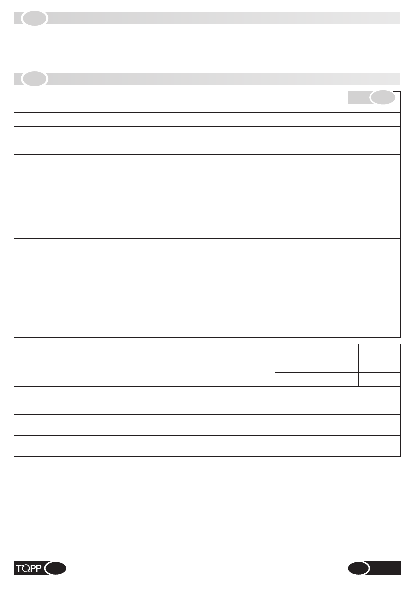
DATI TECNICI
3.3
Nella Tab.1 vengono riportati i dati tecnici che caratterizzano l’attuatore C25
MODELLO
TENSIONE DI ALIMENTAZIONE
ASSORBIMENTO
POTENZA ASSORBITA A CARICO
CARICO MASSIMO APPLICABILE IN SPINTA
CARICO MASSIMO APPLICABILE IN TRAZIONE
FINE CORSA SELEZIONABILE A
(1)
VELOCITÀ DI TRASLAZIONE A VUOTO
DURATA DELLA CORSA MASSIMA A VUOTO
PROTEZIONE CONTRO SCOSSE ELETTRICHE
TIPO DI SERVIZIO S2
(2)
GRADO DI PROTEZIONE DISPOSITIVI ELETTRICI
TEMPERATURA DI FUNZIONAMENTO
Elettronica con avvisatore acustico per segnalazione utente montaggio errato
PESO APPARECCHIO COMPLETO DI STAFFE
PESO LORDO
FINE CORSA SELEZIONATO A
ALTEZZA MINIMA H DEL SERRAMENTO
REGOLAZIONE DELL’ATTACCO AL SERRAMENTO
COLLEGAMENTO IN PARALLELO DI PIÙ ATTUATORI
SULLA STESSA FINESTRA
COLLEGAMENTO IN PARALLELO DI PIÙ ATTUATORI
SU FINESTRE DIVERSE
Tab.
C25 230V
230V ~ 50Hz
0,23 A
45 W
200 N
200 N
200mm / 380mm
37 mm/s
11 s
Classe II
4 minuti
IP 30
-5°C ÷ +50°C
(3)
1,1 Kg
1,5 Kg
200 mm
Sporgere
Vasistas
Sporgere da 0 ÷ 30 mm
Vasistas da 0 ÷ 20 mm
No
Sì
(Vedi schema elettrico)
250 mm
350 mm
1
380 mm
500 mm
1000 mm
(1)
Tolleranza sulla precisione dell’intervento del fine corsa in uscita: ± 10 mm.
(2)
Servizio di durata limitata secondo EN 60034.
(3)
Il dispositivo “buzzer” si attiva automaticamente emettendo un “bip” continuo fino a quando l’attuatore
rimane alimentato. Per ulteriori dettagli sul funzionamento vedi par. 5.6.
6
ISTRUZIONI PER L’INSTALLAZIONE E L’USO
IT
C25
FORMULE PER IL CALCOLO DELLA
3.4
FORZA DI SPINTA O TRAZIONE
2
Cupole o lucernari orizzontali (Fig.3):
F = Forza necessaria per l’apertura o chiusura
P = Peso del lucernario o cupola (solo parte mobile)
F = 0,54 x P
Finestre a sporgere (Fig.4) o a vasistas (Fig.5):
F = Forza necessaria per l'apertura o chiusura
P = Peso della finestra (solo parte mobile)
C = Corsa di apertura della finestra
H = Altezza della finestra (solo parte mobile)
F = (0,54 x P) x (C / H)
DESTINAZIONE D’USO
3.5
L’attuatore è stato progettato e realizzato esclusivamente
per effettuare, tramite un dispositivo di comando,
l’apertura e la chiusura di finestre a sporgere e a vasistas.
Pertanto è assolutamente vietato ogni altro tipo di
impiego e utilizzo al fine di garantire, in ogni momento, la
sicurezza dell’installatore e dell’utilizzatore e l’efficienza
dell’attuatore stesso.
Tutte le condizioni ambientali (temperatura, umidità,
vento, neve, presenza di agenti chimici dell'aria, ecc.) e di
installazione (disallineamenti nei fissaggi tra le staffe e
attacchi, attriti dovuti alle cerniere o guarnizioni,
presenza di braccetti autobilancianti, ecc.) devono
essere attentamente valutate allo scopo di non superare
le prestazioni dell'attuatore indicate in tab.1. In caso
contrario individuare l'attuatore alternativo più adatto ai
fini del corretto utilizzo.
(al serramento e vasistas) e dell’attacco rapido (D-4),
N.1 vite AF d6,3x38 per l’estrazione degli inserti di
bloccaggio dalle rispettive staffe (D-5), N°2 viti M6 per
il fissaggio delle guide di scorrimento all’attuatore
(Rif.D-6), N°1 coppiglia (Rif.D-7), N°2 distanziali di
spessoramento (DX e SX) per applicazione su finestre
vasistas (Rif.D-8) , N.2 guide di scorrimento (Rif.D-9) ;
% N.1 dima di foratura (Rif.E);
% N.1 istruzioni per l’installazione e l’uso (Rif.F);
% N. 1 targhetta di sicurezza (Fig.6).
Assicurarsi che i componenti sopra descritti siano
presenti all’interno della confezione e che
l’attuatore non abbia subito danni durante il
trasporto. Qualora si riscont ra ssero delle
anomalie, è vietato installare l’attuatore, ed è
obbligatorio richiedere l’assistenza tecnica del
rivenditore di fiducia o del fabbricante.
CONFEZIONE
3.6
Ogni confezione standard del prodotto (scatola in
cartone) contiene (Fig.7):
% N.1 Attuatore completo di cavo di alimentazione
elettrica (Rif.A);
% N.2 Staffe di attacco al serramento (DX e SX) (Rif.B) ;
% N.1 Staffa per apertura “vasistas” (Rif.C) ;
% N.1 Confezione minuteria (Rif.D) composta da: n°1
attacco rapido (D-1) con distanziale (D-2), N.2 inserti
per il bloccaggio dell’attuatore alle staffe di attacco (D-
3), N.7 viti AF d4,2 x 19 mm per il fissaggio delle staffe
C25
IT
ISTRUZIONI PER L’INSTALLAZIONE E L’USO
7

IT
4
SICUREZZA
AVVERTENZE GENERALI
4.1
& Il personale operativo deve essere messo al corrente
sui rischi di incidente, sui dispositivi di sicurezza per gli
operatori e sulle norme generali di prevenzione degli
incidenti previste dalle direttive internazionali e dalla
legge vigente nel paese di utilizzo dell’attuatore. Il
comportamento del personale operativo deve in ogni
caso rispettare scrupolos amente le norme sulla
prevenzione degli incidenti vigenti nel paese di utilizzo
dell’attuatore stesso.
& Durante la movimentazione e l'installazione dei
componenti, il personale deve essere dotato degli idonei
dispositivi di protezione individuale (DPI) per eseguire in
totale sicurezza le operazioni richieste.
& Qualunque manomissione o sostituzione non
autorizzata di parti o componenti dell’attuatore e l’utilizzo
di accessori o materiali di consumo diversi dagli originali,
possono rappresentare un rischio di incidente e solleva il
costruttore da qualunque responsabilità civile e penale.
& Nel caso in cui il serramento sia accessibile o
installato ad una altezza da terra inferiore a 2,5m e
nell’eventualità possa essere comandato da personale
utilizzatore non addestrato o da comando remoto, dotare
il sistema di un arresto di emergenza che intervenga
automaticamente per evitare il rischio di schiacciamento
o di trascinamento del corpo inserito tra la parte mobile e
la parte fissa del serramento stesso.
& Le ope razio ni di man utenz ione or dinar ia e
straordinaria che prevedono lo smontaggio anche
parziale dell’attuatore, devono essere effettuate solo
dopo aver interrotto l’alimentazione dell’attuatore stesso.
& Non rimuovere o alterare le targhe apposte dal
costruttore sull’attuatore.
& Questo apparecchio non è adatto all’uso da parte di
persone (inclusi bambini) con capacità fisiche, sensoriali
e mentali ridotte o inesperte, a meno che non vengano
supervisionate ed istruite nell’uso dell’apparecchio da
una persona responsabile per la loro sicurezza. I bambini
devono essere controllati per assicurarsi che non
giochino con l’apparecchio.
& In caso di dubbio, relativamente al funzionamento
dell’attuatore, non usarlo e contattare il costruttore.
DISPOSITIVI DI PROTEZIONE
4.2
Protezione contro il pericolo elettrico: L’attuatore è
protetto contro il pericolo elettrico da contatti diretti e
indiretti.
Le misure di protezione contro i contatti diretti hanno lo
scopo di proteggere le persone dai pericoli derivanti dal
8
ISTRUZIONI PER L’INSTALLAZIONE E L’USO
contatto con parti attive normalmente in tensione. Le
misure di protezione contro i contatti indiretti, invece,
hanno lo scopo di proteggere le persone dai pericoli
derivanti dal contatto con parti conduttrici, normalmente
isolate, le quali potrebbero andare in tensione a causa di
guasti (cedimento dell’isolante).
Le misure di protezione adottate sono le seguenti:
1. isolamento delle parti attive con un corpo in
materiale plastico;
2. involucro con adeguato grado di protezione;
3. pro tez ion e di t ipo p ass ivo c he c ons ist e
nell’impiego di componenti a doppio isolamento,
detti a nc he componenti di c lasse II, o a
isolamento equivalente.
TARGHE RELATIVE ALLA SICUREZZA
4.3
E’ vietato togliere, spostare, deteriorare o rendere in
generale poco visibili le targhe relative alla sicurezza
degli attuatori. Il mancato rispetto di quanto riportato può
causare gravi danni a persone e cose. Il costruttore si
ritiene completamente sollevato da qualsiasi danno
causato dal mancato rispetto di tale avvertenza.
In Fig.6 viene riportata la targa relativa alla sicurezza:
essa deve essere applicata direttamente sulla parte
esterna dell’attuatore o in prossimità dello stesso e, in
ogni caso, in posizione visibile all’installatore e/o
all’operatore.
RISCHI RESIDUI
4.4
Si informano l’installatore e l’utilizzatore che, dopo
l’i nsta llaz ione d egli a ttua tori s ui ser rame nti,
l’azionamento a u t o m a t i c o d e g l i s te s s i p uò
accidentalmente generare il seguente rischio residuo:
% Rischio residuo: Pericolo di schiacciamento o
trascinamento di parti del corpo inserite tra la parte
mobile e la parte fissa del serramento.
% Frequenza di esposizione: Accidentale e quando
l’installatore o l’utilizzatore decida di compiere
un’azione volontaria scorretta.
% Dime ns i o ne del danno: Lesio ni l e g g e re
normalmente reversibili.
% Provvedi me nt i a d o t t a t i : O b b l i g o , p r i m a
dell’avviamento di accertarsi che nelle vicinanze del
serramento non vi siano persone, animali o cose la cui
inco l u mità pos sa a ccide n t almen te e ssere
compromessa. Obbligo, durante l’azionamento
dell’attuatore, di trovarsi in una postazione di
comando sicura che garantisca il controllo visivo della
movimentazione del serramento.
C25
IT
IT
5
INSTALLAZIONE
AVVERTENZE GENERALI
5.1
L’installazione dell’attuatore deve essere eseguita
esclusivamente da personale tecnico competente
e qualificato in possesso dei requisiti tecnico
professionali previsti dalla legislazione vigente nel
paese di installazione.
& L’installazione dell’attuatore deve essere eseguita
esclusivamente con la finestra in posizione di chiusura.
& È assolutamente vietato installare l’attuatore sulla
parte esterna del serramento soggetto agli agenti
atmosferici (pioggia, neve, ecc...).
& È assolutamente vietata la messa in servizio
dell’attuatore in ambienti con atmosfera potenzialmente
esplosiva.
& La struttura ed il materiale di cui è costituito l'infisso
della finestra dovrà essere idoneo per il fissaggio
dell'attuatore e dovrà garantire un buon supporto
d e l l' assi e m e at t u at ore- f i ne stra d ur ant e l a
movimentazione del serramento.
& Prima di procedere all’installazione dell’attuatore è
obbligatorio verificare:
% che la forza di spinta o trazione dell’attuatore siano
sufficienti a garantire la corretta movimentazione del
serramento in base alla tipologia e al peso dello
stesso; è severamente vietato superare i parametri
riportati nella Tab.1;
% che la distanza “D” tra il telaio del serramento (su cui è
previsto il fissaggio dell’attuatore) e l’anta del
serramento (su cui è previsto il fissaggio della staffa)
sia compresa tra 0 mm e 30 mm per il montaggio a
sporgere (vedi Fig.8) e tra 0 mm e 20 mm per il
montaggio a vasistas (vedi Fig.18 e Fig. 18a);
% che, nei serramenti con apertura a vasistas, siano
montati su entrambi i lati della finestra due finecorsa a
compasso o un sistema di sicurezza alternativo onde
evitare la caduta accidentale della finestra;
% che la superficie di fissaggio dell’attacco rapido sia
perfettamente piana e/o livellata.
FINESTRE A SPORGERE
5.2
Per installare un attuatore C25 su finstre con apertura a
sporgere procedere nel seguente modo:
% Aprire la confezione (par 3.6) ed estrarre i vari
componenti;
% Fig.9 - Tracciare con una matita la mezzeria “X” del
serramento;
% Fig.10 - Applicare la dima al serramento (lato A)
all ine a ndo la al l a mez zeri a “X” t rac c iat a in
precedenza;
@ Per serramenti non complanari è necessario
tagliare la parte di dima interessata e applicarla al
serramento avendo cura di mantenerla nella
stessa posizione di riferimento.
Con un trapano idoneo, eseguire nel serramento i fori
indicati sulla dima (2 per il fissaggio dell’attacco
rapido e 2 per il fissaggio di ciascuna staffa);
% Fig.11 e Fig.12 - Rimuovere la dima e fissare con viti
d4,2x19 l’attacco rapido e le staffe di attacco al
serramento;
@ Nel caso in cui il valore del sormonto “D” sia
compreso tra 20÷30mm, fissare l’attacco rapido
servendosi dell’apposito distanziale e delle viti
adatte (Fig.8 Rif.2).
@ Le viti presenti nella confezione sono idonee per
serramenti in alluminio. Per il fissaggio su infissi in
legno, utilizzare viti da legno Ø4,2 di lunghezza
adeguata.
% Fig.13 - Fissare le guide di scorrimento all’attuatore
utilizzando le viti M6 contenute nella confezione
minuteria (coppia di serraggio della vite = 2,5Nm);
% Fig.14 - Inserire l’attuatore nelle staffe di attacco
assicurandosi che la parete interna dentata della
guida scorra a contatto della superficie dentata della
rispettiva staffa;
% Fig.15 - Sistemare l’attuatore nella posizione più
idonea da permettere un comodo aggancio del
terminale catena all’attacco rapido;
@ Qualora il terminale catena non sia in asse con
l’attacco rapido allentare le viti di fissaggio e
posizionare il tutto correttamente; la mancata
coassialità può provocare danni all’attuatore e al
serramento.
% Fig.16 - Agganciare il terminale catena all’attacco
rapido e regolare ulteriormente la posizione
dell’attuatore sulle staffe affinché le guarnizioni del
serramento siano completamente compresse (vedi
par. 5.6). Bloccare quindi l’attuatore alle staffe di
attacco con gli appositi inserti di bloccaggio;
Il mancato bloccaggio dell’attuatore mediante gli
inserti può provocare gravi danni a persone e
cose.
% Fig. 17 - Regolare la corsa di apertura tramite lo
switch posto sul lato destro dell’attuatore in base
all’apertura dell’anta;
@ L’attuatore viene fornito con corsa tarata a
200mm. La selezione della corsa deve essere
effettuata esclusivamente da personale tecnico
competente e qualificato e ad attuatore spento.
@ Per modificare la corsa di apertura del C25
utilizzare un cacciavite con punta idonea e,
avendo cura di inserirlo fino alla base dello
switch, spostarlo completamente. Una posizione
intermedia (non corretta) dello switch provoca il
blocco dell’attuatore.
@ Verificare che la corsa selezionata sia inferiore di
qualche centimetro alla corsa effettiva consentita
C25
IT
ISTRUZIONI PER L’INSTALLAZIONE E L’USO
9
da fermi meccanici, limitatori a compasso o
impedimenti all'apertura dell'anta.
@ Qualora l’attuatore venisse tarato con corsa
380mm, assicurarsi che, durante l’azionamento
del motore, la catena non vada a toccare il
serramento. In questo caso regolare la corsa a
200mm.
% Fig.31 - Effettuare i collegamenti elettrici in conformità
a quanto prescritto al par. 5.4 e in riferimento allo
schema elettrico.
FINESTRE A VASISTAS
5.3
Per installare l’attuatore C25 su finstre con apertura a
vasistas procedere nel seguente modo:
% Aprire la confezione (par 3.6) ed estrarre i vari
componenti;
% Fig.19 - Tracciare con una matita la mezzeria “Y” del
serramento;
% Fig.20 - Applicare la dima al serramento (lato B)
allineandola alla mezzeria “Y” tracciata in precedenza;
@ Per serramenti non complanari è necessario
tagliare la parte di dima interessata e applicarla al
serramento avendo cura di mantenerla nella
stessa posizione di riferimento.
Con un trapano idoneo, eseguire nel serramento i 7
fori indicati sulla dima (3 per il fissaggio della staffa
vasistas e 2 per ciascuna staffa di fissaggio al
serramento);
% Fig.21 - Rimuovere la dima e fissare con viti d4,2x19
le staffe di fissaggio e la staffa vasistas;
@ Nel caso in cui il valore del sormonto “D” sia
compreso tra 10 e 20mm, fissare le staffe di
attacco servendosi degli appositi distanziali di
spessoramento (vedi Fig.18a).
@ Le viti presenti nella confezione sono idonee per
serramenti in alluminio. Per il fissaggio su infissi in
legno, utilizzare viti da legno Ø4,2 di lunghezza
adeguata.
% Fig.22 - Fissare le guide di scorrimento all’attuatore
utilizzando le viti M6 contenute nella confezione
minuteria (coppia di serraggio della vite = 2,5Nm);
% Fig.23 - Inserire l’attuatore nelle staffe assicurandosi
che la parete interna dentata della guida scorra a
contatto della superficie dentata della rispettiva staffa;
% Fig.24 e Fig.25 - Agganciare il terminale catena alla
staffa vasistas e regolare la posizione dell’attuatore
affinché le guarnizio ni del se rr am en to siano
completamente compresse (vedi par. 5.6);
@ Qualora il terminale catena non sia in asse con la
staffa vasistas allentare le viti di fissaggio e
posizionare il tutto correttamente; la mancata
coassialità può provocare danni all’attuatore e al
10
ISTRUZIONI PER L’INSTALLAZIONE E L’USO
serramento.
Bloccare l’attuatore alle staffe con gli appositi inserti;
Il mancato bloccaggio dell’attuatore alle staffe
mediante gli inserti, può provocare gravi danni a
persone e cose.
% Fig.26 - Inserire la coppiglia negli appositi fori della
staffa vasistas fino a portare in battuta l’occhiello sulla
staffa stessa; deformare quindi l’estremità opposta
della coppiglia fino al completo bloccaggio;
% Fig.27 - Regolare la corsa di apertura tramite lo
switch posto sul lato destro dell’attuatore in base
all’apertura dell’anta;
@ L’attuatore viene fornito con corsa tarata a 200
mm. La selezione della corsa deve essere
effettuata esclusivamente da personale tecnico
competente e qualificato e ad attuatore spento.
@ Per modificare la corsa di apertura del C25
utilizzare un cacciavite con punta idonea e,
avendo cura di inserirlo fino alla base dello
switch, spostarlo completamente. Una posizione
intermedia (non corretta) dello switch provoca il
blocco dell’attuatore.
@ Verificare che la corsa selezionata sia inferiore di
qualche centimetro alla corsa effettiva consentita
da fermi meccanici, limitatori a compasso o
impedimenti all'apertura dell'anta.
@ Qualora l’attuatore venisse tarato con corsa
380mm, assicurarsi che, durante l’azionamento
del motore, la catena non vada a toccare il
serramento. In questo caso regolare la corsa a
200mm.
% Fig.31 - Effettuare i collegamenti elettrici in conformità
a quanto prescritto al par. 5.4 e in riferimento allo
schema elettrico.
COLLEGAMENTO ELETTRICO
5.4
Il collegamento elettrico dell’attuatore deve
essere eseguito esclusivamente da personale
tecnico competente e qualificato in possesso dei
requisiti tecnico professionali previsti dalla
legislazione vigente nel paese di installazione che
rilascia al cliente la dichiarazione di conformità del
collegamento e/o dell’impianto realizzato.
& Qualsiasi tipo di materiale elettrico (spina, cavo,
morsetti, ecc...) utilizzato per il collegamento deve
essere idoneo all’impiego, marcato “CE” e conforme ai
requisiti previsti dalla legislazione vigente nel paese di
installazione.
& La linea di alimentazione elettrica a cui viene
collegato l’attuatore deve essere conforme ai requisiti
previsti dalla legislazio ne vige nt e nel paese di
installazione, soddisfare le caratteristiche tecniche
riportate nella tab. 1 e nella targa dati e marcatura “CE”
C25
IT

(par. 3.1).
& La sezione dei cavi della linea di alimentazione
elettrica deve essere opportunamente dimensionata in
base alla potenza elettrica assorbita (vedi targa dati e
marcatura “CE”).
& Per assicurare una efficace separazione dalla rete
elettrica di alimentazione, è obbligatorio installare a
monte dell’apparecchio un interruttore momentaneo
(pulsante) bipolare di tipo approvato. A monte della linea
di comando è obbligatorio installare un interruttore
generale di alimentazione bipolare con apertura dei
contatti di almeno 3 mm.
& Prim a di ese guire il coll egame nto elettri co
dell’attuatore, verificare la corretta installazione dello
stesso sul serramento.
& Prim a di ese guire il coll egame nto elettri co
dell’attuatore verificare che il cavo di alimentazione
elettrica non sia danneggiato. Nel caso in cui lo fosse,
quest’ultimo deve essere sostituito dal costruttore, dal
servizio di assistenza tecnica o da operatori addetti.
DISPOSITIVI DI COMANDO
5.5
I dispositivi di comando impiegati per azionare l’attuatore
devono garantire le condizioni di sicurezza previste dalla
legislazione vigente nel paese di utilizzazione.
A seconda delle diverse tipologie di installazione gli
attuatori possono essere azionati dai seguenti dispositivi
di comando:
% Pulsante manuale: Pulsante commutatore a due poli
con posizione Off centrale, con comando di tipo
“uomo presente”;
% Opzionale: Unità di comando e alimentazione:
Centrali a microprocessore TOPP modello TF che
comandano il singolo attuatore o simultaneamente
più attuatori tramite uno o più pulsanti manuali, un
telecomando a raggi infrarossi o un radiocomando a
433 Mhz. A queste centrali si possono collegare i
sensori pioggia, il sensore vento ed il sensore
luminosità;
@ Le centrali eventualmente utilizzate, dovranno
fornire tensione al C25 per un tempo massimo di
120 secondi.
REGOLAZIONE DELLA CHIUSURA
5.6
DEL SERRAMENTO
La corretta regolazione della chiusura del serramento
garantisce la durata e la tenuta delle guarnizioni e il buon
funzionamento dell’attuatore.
Un buon metodo per eseguire una corretta installazione
dell’attuatore consiste nell’effettuare una prova completa
di apertura e chiusura del serramento e, una volta
terminata la fase di chiusura, verificare che:
% le guarnizioni della finestra siano correttamente
C25
IT
ISTRUZIONI PER L’INSTALLAZIONE E L’USO
compresse;
% che la catena dell’attuatore sia completamente
rientrata.
Nel caso in cui la catena dell’attuatore non rientri
completamente, si provoca il mancato intervento del finecorsa relativo al rientro catena. In questa situazione il
motore dell’attuatore rimane in condizioni di massimo
sforzo sino all’intervento della protezione elettronica e
all’attivazione di un avvisatore acustico, denominato
“BUZZER”, il quale emette un “bip” continuo fino a
quando l’attuatore rimane collegato all’alimentazione.
Questo sistema di sicurezza aggiuntivo è stato concepito
al fine di offrire un rapido sistema per riconoscere
eventuali anomalie nel montaggio dell’apparecchio.
Nonostante ciò è obbligatorio osservare tutte le
procedure di installazione descritte nel presente
manuale. In entrambe le situazioni è pertanto necessario
regolare nuovamente la posizio ne dell’attuatore
procedendo nel seguente modo (Fig. 28):
1. togliere l’alimentazione;
2. inserire la vite autofilettante TC d6,3x38 (presente
nella confezione) nel foro centrale del primo inserto
di bloccaggio;
3. con un cacciavite idoneo portare in battuta la vite fino
alla completa estrazione dell’inserto stesso;
4. estrarre il secondo inserto di bloccaggio ripetendo
quanto descritto nei punti 2 e 3;
5. regolare la posizione dell’attuatore;
6. inserire nuovamente entrambi gli inserti.
MANOVRE DI EMERGENZA
5.7
Nel caso si renda necessario aprire il serramento
manualmente per mancanza di energia elettrica o
bloccaggio del meccanismo, seguire le seguenti
istruzioni:
% Apertura a sporgere: Fig. 29- tirare il pulsante di
sgancio dell’attacco rapido nella direzione indicata
dalla freccia e far ruotare l’attuatore verso l’alto fino al
disimpegno dello stesso dall’attacco rapido.
% Apertura a vasistas: Fig. 30 - Inserire un cacciavite
a taglio tra la staffa vasistas ed il terminale catena e
far leva fino al disimpegno del terminale catena
stesso.
Pr ima di es eguir e qu als iasi ti po d i inter vento
sull’attuatore e sul serramento è obbligatorio:
% disconnettere il dispositivo di sezionamento dalla rete
di alimentazione;
% lucchettare l’interruttore generale del dispositivo di
sezionamento installato nella linea di alimentazione
elettrica, onde evitare l’avvio inatteso; se l’interruttore
generale non è lucchettabile, è obbligatorio esporre
un cartello con divieto di azionamento.
11
6
USO E FUNZIONAMENTO
UTILIZZO DELL’ATTUATORE
6.1
L’utilizzazione dell’attuatore deve essere eseguita
esclusivamente da un utilizzatore che agisca in
conformità delle istruzioni riportate nel presente
manuale e/o nel manuale del dispositivo di
comando dell’attuatore (unità di alimentazione e
comando).
& L’utilizzo dell’attuatore consente di comandare in
automatico l’apertura e la chiusura del serramento in
base al tipo di dispositivo di comando installato (vedi
par. 5.5).
& È obbligatorio che l’utilizzatore, prima di azionare
l’attuatore, si accerti che vicino e/o sotto al serramento
non ci sia la presenza di persone, animali e cose la cui
incolumità accidentalmente possa essere compromessa
(vedi par. 4.4).
& È obb li gator io c h e l’uti li zzato re , duran te
l’azionamento del dispositivo di comando dell’attuatore,
si trovi in una postazione di comando sicura e che
garantisca il controllo visivo della movimentazione del
serramento.
& È obbligatorio verificare costantemente nel tempo
IT
7
7.1
Nel caso in cui l’attuatore presentasse delle anomalie di
funzionamento, contattare il costruttore.
Qualsiasi i nt er vento sull’attuatore (es. Cavo di
alimentazione ecc...), o suoi componenti, deve essere
fatto solo ed esclusivamente da tecnici qualificati dal
costruttore. Topp non si assume alcuna responsabilità
per interventi eseguiti da persone non autorizzate.
Le operazioni di manutenzione ordinaria e straordinaria
ch e pre ved ono l o sm ont agg io an che p arz ial e
dell’attuatore, devono essere effettuate solo dopo aver
interrotto l’alimentazione dell’attuatore stesso.
Il progetto dell'attuatore prevede l'utilizzo di componenti
ch e no n ri chied ono ma nuten zione per iodic a o
straordinaria di rilevante importanza.
L’attività di manutenzione consigliata deve prevedere in
ogni caso l’effettuazione periodica (ogni 6 mesi) di
almeno i seguenti interventi: la pulizia degli elementi
facenti parte del gruppo di attuazione, la sostituzione di
componenti che presentino segni di danneggiamento
superficiale quali: lesioni, fessurazioni, scolorazioni,
ecc., la tenuta dei sistemi di fissaggio (staffe e viti),
l' eve ntual e defor maz ione de l se rra mento e la
conseguente tenuta delle guarnizioni, in fine controllare
lo stato di cablaggi e connessioni.
Nel caso in cui risulti necessario, rimuovere lo sporco
dalla catena con un panno morbido e ripristinare
successivamente sulla stessa un leggero strato di grasso
(tipo nyogel788 - Tecnolube Seal).
APPENDICI
MANUTENZIONE
l’efficienza funzionale e le prestazioni nomina li
dell’attuatore, del serramento dove esso è installato e
dell’impianto elettrico effettuando, quando necessario,
interventi di ordinaria o straordinaria manutenzione che
garantiscano le condizioni di esercizio nel rispetto delle
norme di sicurezza.
& In presenza di neve, la finestra a cupola motorizzata
non deve essere movimentata.
& Tutti gli interventi sopra descritti devono essere
es egu iti esc lusiv ame nte da pe rsona le te cnico
competente e qualificato in possesso dei requisiti tecnico
professionali previsti dalla legislazione vigente nel paese
di installazione.
& Per un corretto funzionamento della automazione, si
consiglia l'utente di effettuare una manutenzione
periodica della stessa, secondo quanto indicato al par
7.1.
& Topp avvisa l'utente che, ai sensi dell'art. 8 del decreto
ministeri ale n . 38 del 22.1.2008, il propriet ario
dell'impianto deve adottare le misure necessarie per
conservarne le caratteristiche di sicurezza previste dalla
normativa vigente in materia, tenendo conto delle
istruzioni per ll’uso e la manutenzione predisposte dal
fabbricante dell'apparecchiatura installata e dall'impresa
installatrice.
Tale attività di manutenzione potrà essere svolta o da
TOPP, in forza di uno specifico accordo raggiunto con
l'utente, o dall'installatore o da altro personale tecnico,
competente e qualificato nonché in possesso di tutti i
requisiti di legge.
DEMOLIZIONE
7.2
La demolizione dell’attuatore deve avvenire nel rispetto
della legislazione vigente in materia di tutela ambientale.
Proc ed ere alla differenziazione delle parti c he
costituiscono l’attuatore secondo la diversa tipologia di
materiale (plastica, alluminio, ecc...).
RICAMBI ED ACCESSORI A
7.3
RICHIESTA
È vietato l’impiego di ricambi ed accessori “non originali”
che possono compromettere la sicurezza e l’efficienza
dell’attuatore.
I ricambi e gli accessori originali devono essere richiesti
esclusivamente al rivenditore di fiducia o al fabbricante
comunicando il tipo, il modello, il numero di serie e l’anno
di costruzione dell’attuatore.
12
ISTRUZIONI PER L’INSTALLAZIONE E L’USO
IT
C25

EN
IT
1- EC DECLARATION OF INCORPORATION OF PARTLY COMPLETED MACHINERY..... pag. 14
2- GENERAL REMARKS
2.1- General precautions .....................................................................................................pag. 15
2.2- Description of personnel ...............................................................................................pag. 15
2.3- Technical assistance .....................................................................................................pag. 15
3- TECHNICAL DESCRIPTION
3.1- Rating plate and “CE” marking .....................................................................................pag. 15
3.2- Name of components and dimensions .........................................................................pag. 16
3.3- Technical data...............................................................................................................pag. 16
3.4- Formulas to calculate thrust force or traction force ......................................................pag. 17
3.5- Intended usage.............................................................................................................pag. 17
3.6- Pakage .........................................................................................................................pag. 17
4- SAFETY
4.1- General precautions .....................................................................................................pag. 18
4.2- Protection devices ........................................................................................................pag. 18
4.3- Safety plates.................................................................................................................pag. 18
4.4- Residual risks ...............................................................................................................pag. 18
5- INSTALLATION
5.1- General precautions .....................................................................................................pag. 19
5.2- Top hung windows ........................................................................................................pag. 19
5.3- Bottom hung windows...................................................................................................pag. 20
5.4- Electric connection........................................................................................................pag. 20
5.5- Control devices.............................................................................................................pag. 21
5.6- Adjusting the window closure .......................................................................................pag. 21
5.7- Emergency procedures.................................................................................................pag. 21
INDEX
6- USE AND OPERATION
6.1- Use of the actuator .......................................................................................................pag. 22
7- APPENDIX
7.1- Maintenance .................................................................................................................pag. 22
7.2- Demolition.....................................................................................................................pag. 22
7.3- Spare parts and accessories upon request ..................................................................pag. 22
8- FIGURES..............................................................................................................................pag. 23
C25
EN
INSTALLATION AND USE INSTRUCTIONS
13

IT
1
EC DECLARATION OF INCORPORATION OF PARTLY COMPLETED MACHINERY
ORIGINAL
The undersigned, in the name of and
behalf of the following company
Topp S.r.l.
Via Galvani, 59
36066 Sandrigo (VI)
Italia
herewith declares that the person authorised to compile the technical file is
Name: Bettiati Roberto - Topp S.r.l.
Address: via Galvani,59 36066 Sandrigo (VI)
and that to the partly completed machinery
CHAIN ACTUATOR FOR WINDOW AUTOMATION
Type: C25
Model: C25/230V
the following essential requisites of the
2006/42/EC Machinery Directive (including all applicable amendments)
have been applied and fulfilled: Enclosure I: 1.5.1; 1.5.2; 1.5.10; 1.5.11
that the relevant technical documentation is compiled in accordance with part B of Annex VII of the above
mentioned Machinery Directive..
The above identified partly completed machinery is also in conformity with the all the relevant provisions
of the following directives (including all applicable amendments)
EMC Directive 2014/30/EU
RoHS II Directive 2011/65/EU
The following harmonised standards have been applied:
EN 60335-2-103:2015 (applicable parts)
EN 55014-1:2006 + A1:2009 + A2:2011
EN 55014-2:2015
EN 61000-6-2:2005.
EN 61000-6-3:2007 + A1:2011 + AC:2012.
EN 50581:2012
and the following technical documents:
EN 62233:2008
The undersigned also undertakes the obligation, in response to a duly reasoned request by the national
market surveillance authorities, to transmit to the a.m. authorities, in electronic or paper format, the
relevant technical documentation on the partly completed machinery.
The above identified partly completed machinery must not be put into service until the final machinery
into which it is to be incorporated has been declared in conformity with the provisions of the above
mentioned Machinery Directive.
This declaration of conformity is issued under the sole responsibility of the manufacturer.
Date: Sandrigo01/02/2018 Signature: Matteo Cavalcante
Amministratore ................................................................
14
INSTALLATION AND USE INSTRUCTIONS
EN
C25

IT
2
2.1
The fitter and the user must read and understand
all the parts of this manual before installing and
using the actuator.
GENERALI REMARKS
GENERAL PRECAUTIONS
& This manual is an integral part of the actuator and
must be kept for future references.
& This manual is intended for the proprietor, users,
fitters and for technicians who are qualified to carry out
maintenance on the actuator and is therefore appropriate
to keep it along with the entire enclosed documentation,
in a place where it can be easily accessed and wherein all
operators can be aware of.
& The purpose of this manual is to provide all the
necessary information to use the actuator correctly and to
manage it in most independent and secure way as
possible: TOPP srl will not be held responsible for any
damages to people, animals or things if the user fails to
comply with the instructions herein described.
& This manual was written by TOPP srl and is entitled to
all copyrights. None of the parts of this manual should be
reproduced or disclosed without a written authorization
from the manufacturer.
& TOPP srl reserves the right to modify and improve the
manual and its products described at any time without
giving prior notice.
& In order for the automation unit to operate correctly,
we recommend carrying out periodical maintenance on it,
as indicated in par. 7.1 of this manual.
& The warranty on the actuator will not be honored if
product is not installed and used according to the
instructions provided and the regulations shown in this
instruction manual and if it is used with non-genuine
parts, accessories, spare parts and/or control/feeding
units.
PERSONNAL DESCRIPTION
2.2
Electrical engineer
technicians must be capable of installing the actuator, set
it going and work under voltage inside electric cubicles
and branch boxes. Specialized technicians are also
qualified to carry out all electrical interventions,
mechanical settings and maintenance. Therefore, the
installation of the actuator must be carried out exclusively
by competent and qualified technical personnel with the
professional technical requirements provided by current
laws in the country in which the actuator is installed.
The user
The user is the personnel who capable of controlling the
actuator under normal conditions using the respective
commands. Moreover, the user must be capable of
working with the actuator "under maintenance" in order
to carry out simple ordinary maintenance operations
(cleaning) and setting up or resetting the actuator after
any forced halts.
Users must not carry out operations that are reserved to
maintenance technicians or specialized technicians.
The manufacturer will not be held liable for damages
due to non-compliance against this prohibition.
The use of the actuator must be exclusively assigned to
users who act in compliance with the instructions stated
on this manual and on manuals of TOPP devices that
are linked to it (i.e. power-supply unit).
The installation technician shall accept full responsibility
for any installation errors and for any failure to adhere to
the instructions provided in this manual. The installation
technician shall therefore be exclusively liable for any
damages caused to users and/or third parties that may
arise as a result of incorrect installation.
TECHNICAL ASSISTANCE
2.3
Contact the installation technician or retailer for
assistance.
IT
3
3.1
The CE marking certifies the compliance of the machine
with essential safety and health requirements set under
European Directives concerning products.
It is made up of an adhesive small polyester plate,
screen-printed with bl ack and has the following
dimensions: L= 50 mm - H= 36 mm, it is affixed on the
external part of the actuator. The following data (legibly
and indelibly) is indicated on the plate .
TECHNICAL DESCRIPTION
RATING PLATE AND “EC” MARKING
% the manufacturer's logo and address;
% type and model;
C25
EN
INSTALLATION AND USE INSTRUCTIONS
% voltage (V) and power frequency (Hz);
% the intensity of absorbed current (A);
% absorbed electric power P (W);
% thrust and traction force F (N);
% service type S2 (min);
% idle translation speed (mm/s);
% protection grade (IP);
% CE marking;
% the symbol for “WEEE” Directive 2002/96/CE;
% the symbol for double insulation;
% serial number.
15

NAME OF COMPONENTS AND DIMENSIONS
3.2
Fig.2a and Fig.2b show the names of the main parts that make up the actuator.
TECHNICAL DATA
3.3
Tab 1 shows the technical data that makes up actuator C25.
MODEL
SUPPLY VOLTAGE
ABSORBED CURRENT
ABSORBED POWER UNDER LOAD
MAXIMUM APPLICABLE THRUST LOAD
MAXIMUM APPLICABLE TRACTIVE LOAD
SELECTABLE AT LIMIT SWITCH
(1)
IDLE TRANSLATION SPEED
DURATION OF MAXIMUM IDLE STROKE
PROTECTION AGAINST ELECTRIC SHOCK
TYPE OF SERVICE S2
(2)
PROTECTION GRADE FOR ELECTRIC APPLIANCES
OPERATING TEMPERATURE
Electronics with acoustic alarm to signal an incorrect assembling to the user
ACTUATOR WEIGHT INCLUDING BRACKETS
GROSS WEIGHT
LIMIT SWITCH SELECTED AT
WINDOW MINIMUM HEIGHT (H)
ADJUSTMENT OF THE WINDOW FRAME CONNECTION
PARALLEL CONNECTION OF MORE ACTUATORS
ON THE SAME WINDOW
PARALLEL CONNECTION OF MORE ACTUATORS
ON DIFFERENT WINDOWS
Top hung
Bottom hung
Top hung window from 0 ÷ 30 mm
Bottom hung window from 0 ÷ 20 mm
No
Yes
(See wiring diagram)
1
Tab.
C25 230V
230V ~ 50Hz
0,23 A
45 W
200 N
200 N
200mm / 380mm
37 mm/s
11 s
Class II
4 minutes
IP 30
-5°C ÷ +50°C
(3)
1,1 Kg
1,5 Kg
200 mm
250 mm
350 mm
380 mm
500 mm
1000 mm
(1)
Tollerance on the precision of the output limit switch intervention: ± 10 mm.
(2)
Limited service duration according to EN 60034.
(3)
The “buzzer” device activates automatically and emits a continuos “beep” until the actuators stays
powered. For further details on the functioning see par. 5.6.
16
INSTALLATION AND USE INSTRUCTIONS
EN
C25

FORMULAS TO CALCULATE THRUST
3.4
FORCE OR TRACTION FORCE
2
Cupola or horizontal skylights (Fig.3):
F = Force required to open or close
P = Weight of the skylight or cupola (only mobile part)
F = 0,54 x P
Top h ung w ind ows ( Fig .4) or bo tto m hun g
windows(Fig.5):
F = Force required to open or close
P = Weight of the window (only mobile part)
C = Window opening stroke
H = Window height (only mobile part)
F = (0,54 x P) x (C / H)
INTENDED USAGE
3.5
The actuator was designed and made exclusively to
open and close top hung and bottom hung windows using
a control device. Therefore, in order to ensure the safety
of the fitter and of the user at all times and the efficiency of
the actuator itself, it is absolutely forbidden to use it for
other purposes.
Che c k car e full y a ll env iron m enta l cond i tion s
(temperature, humidity, wind, snow, potential chemical
agents, etc.) and installation settings (misaligned fitting of
brackets and attachment to the frame, frictions produced
by hinges or gaskets, use of self-balancing window stays,
etc.) it is recommended that they not exceed the actuator
performances shown in the technical table. If they do,
please find an alternative and more suitable product for
your application.
d6.3x38 to remove the coupling inserts from the
respective brackets (D-5), n°2 EI screws M6x13 to
fasten the slide guides to the actuator (Rif.D-6), n°1
split pin (Rif.D-7), No. 2 shims (right and left) for
bottom hung windows (Ref. D-8), N.2 slide guides
(Rif.D-9) ;
% N.1 drill template (Rif.E);
% N.1 user and installation instructions (Rif.F);
- N. 1 safety plate (Fig.6).
Make sure that the above stated parts are inside
the package and check to see if the actuator
suffered any damages during transportation. If
there are abnormalities it is forbidden to install
the actuator; the user must contact a reliable
reseller technical assistance service or the
manufacturer.
PAKAGE
3.6
Each standard product package (carton box) has the
following (Fig.7):
% N.1 actuator including power supply cord (Rif.A);
% N.2 window coupling brackets (right and left) (Rif.B) ;
% N.1 bracket for “bottom hung window” opening
(Rif.C);
% N.1 small part package (Rif.D) made up of the
following: n°1 quick coupling (D-1) with spacer (D-2),
N.2 inserts to lock the actuator to the coupling brackets
(D-3), N.7 AF screws d4.2 x 19 mm to fasten the
brackets and the quick coupling (D-4), N.1 AF screw
C25
EN
INSTALLATION AND USE INSTRUCTIONS
17

IT
4
SAFETY
GENERAL PRECAUTIONS
4.1
& The operating personnel must be aware of accident
risks, safety devices for operators and general accident
prevention standards set out by international directives
and by current regulations in the country in which the
actuator is used. The behaviour of the operating
personnel must, in any case, comply strictly with current
accident prevention standards in the country in which the
actuator is being used.
& During handling and installation of the parts, the
personnel shall be equipped with suitable personal
protection equipment (PPE) so as to perform the works
required under safe conditions.
& Any tampering or non-authorized replacements of
parts or components of the actuator and the use of nonoriginal accessories or consumable materials can entail
accident risks and the manufacturer will be exempted
against any civil and criminal liability.
& If the windows are accessible or installed at a ground
height lower than 2.5 meters and if they can be controlled
by personnel without any training or by means of a
remote control, the system must be equipped with an
emerge ncy hal ting sys tem t hat c an in ter ven e
automatically to prevent risk of crushing or dragging the
body fitted between the mobile part and the fixed part of
the window itself.
& Ordinary and extra-ordinary maintenance operations
that require the disassembling of the actuator (even
partial), must be made only after interrupting the power of
the actuator itself.
& Do not remove or alter the plates affixed on the
actuator by the manufacturer.
& This appliance is not suitable to use by persons with
limited physical, sensory and mental abilities (including
children) or inexperienced persons, unless they are
supervised and instructed on how to use the device by a
person who is responsible for their own safety. Children
must be monitored to make sure they do not play with the
appliance.
& In case of doubt on the functioning of the actuator, do
not use it and contact the manufacturer.
PROTECTION DEVICES
4.2
Protection against electrical hazards: The actuator is
protected against direct and indirect contact electrical
hazards.
Protective measures against direct contacts are aimed at
protecting persons against hazards derived from
contacts with live parts that are normally energized. On
the contrary, protective measures against indirect
18
INSTALLATION AND USE INSTRUCTIONS
contacts are aimed at protecting persons against
hazards derived from current-conducting parts that are
normally isolated and that can be energized because of
faults (insulating failures).
The protective measures adopted are the following:
1. insulating live parts with a plastic material body;
2. a covering with an appropriate protection grade;
3. passive protection that consists in using parts with
double insulation, also class II components or with
equivalent insulation.
SAFETY PLATES
4.3
It is forbidden to remove, transfer, damage or make the
safety plates for the actuator not very visible. Failure to
comply with the above stated may result in serious
injuries to persons and damages to things. The
manufacturer will be fully exempted against any damage
that is caused because of non-compliance to such
precautions. Fig.6 shows the safety plate: it must be
applied directly on the outer part of the actuator or close
to it and, in any case, in a position that is visible to the fitter
and/or operator.
RESIDUAL RISKS
4.4
The fitter and the user are informed that after installing
the actuators onto the windows, the automatic operation
of the windows can accidentally cause the following
residual risk:
% Residual risk: Risk of crushing or dragging the parts
of the body that are fitted between the mobile part and
the fixed part of the window.
% Exposure rate: Accidental and when the fitter or the
user decides to perform an incorrect voluntary action.
% The extent of the damage: Light damages that are
normally reversible.
% Adopted measures: Before starting make sure that
near the windows there are no persons, animals or
things whose safety can be accidentally compromised.
While activating the actuator the user must be in a
secure control position that can ensure a visual control
of the moving window.
C25
EN

IT
5
INSTALLATION
GENERAL PRECAUTIONS
5.1
The installation of the actuator must be carried out
exclusively by competent and qualified technical
pers on ne l with the prof es si onal techn ic al
requirements provided by current laws in the
country in which the actuator is installed.
& The actuator must be installed exclusively with the
windows closed.
& It is absolutely forbidden to install the actuator on the
outer part of the window that is subjected to atmospheric
agents (rain, show, etc.).
& It is absolutely forbidden to setup the actuator in areas
that may be potentially explosive.
& Check the adequacy of the window and the suitability
of the materials of the window and/or frame on which the
actuator will be fastened and it must ensure a good
support of the actuator-window assembly during the
movement.
& Before installing the actuator the user must verify the
following:
% the thrust or traction force of the actuator must be
enough to ensure the correct movement of the window
according to its type and weight; it is strictly forbidden to
exceed the parameters stated on Tab.1;
% the distance “D” between the window frame (wherein
the actuator is supposed to be secured) and the window
leaf (wherein the bracket is supposed to be secured)
must be between 0 mm and 30 mm for the top hung
installation (see Fig.8) and between 0 and 20 mm for
the bottom hung installation (see Fig.18 and Fig.18a);
% two hinged limit switches must be installed on both
sides of bottom hung windows, or an alternative safety
system that can prevent the window from falling
accidentally;
% the fastening areas of the quick coupling must be
completely flat and/or levelled.
TOP HUNG WINDOWS
5.2
To install actuator C25 on top hung opening windows
proceed as follow:
% Open the package (par. 3.6) and remove the various
componentsi;
% Fig.9 - Use a pencil and trace out the centre line “X” of
the window;
% Fig.10 - Put the template on the window (side A) and
align it to the centre line "X" that was traced previously;
@ For non-coplanar windows the part of the
template that is involved must be cut and fit it onto
the window; make sure to keep it in the same
reference position.
Using a suitable drill, make two holes on the window
indicated on the template (2 for securing the quick
coupling and 2 for fastening each bracket);
% Fig.11 and Fig.12 - Remove the template and secure
the quick coupling using d4.2x19 screws and fasten
the coupling brackets to the window;
@ If the overlapping value “D” is between 20÷30mm,
secure the quick coupling using the special spacer
and the suitable screws (Fig.8 Rif.2).
@ The screws on the package are suited for
aluminium windows. To mount wooden windows,
use wood screws Ø4.2 with an appropriate length.
% Fig.13 - Fasten the slide ways to the actuator by using
the M6 screws supplied with the small parts package
(screw tightening torque = 2,5Nm).
% Fig.14 - Place the actuator onto the coupling brackets;
make sure the teethed inner wall of the guide slides
when contacted with the teethed surface of the
respective bracket.
% Fig.15 - Arrange the actuator into the most suitable
position in order to allow an easy connection of the
chain terminal to the quick coupling.
@ If the chain terminal is not in axis with the quick
coupling, loosen the fixing screws and position
everything correctly; if there is no coaxiality, the
actuator and the window can be damaged.
% Fig.16 - Fasten the chain terminal to the quick
coupling and adjust the position of the actuator on the
brackets so the window seals can be completely
pressed (see par. 5.6). Thus, lock the actuator to the
coupling brackets with the special clamping inserts.
If the actuator is not locked with the inserts, this
may cause serious injuries and damages to
persons and things.
% Fig. 17 - Adjust the opening stroke using the switch
located on the right side of the actuator according to
the window leaf opening.
@ The actuator is supplied with a stroke calibrated
to 200mm. The stroke should only be selected by
competent and qualified technical personnel and
must be done with the actuator switched off.
@ To modify the C2 5 o penin g s troke use a
screwdriver with a suited point and make sure to
fit it up to the base of the switch, hence move it
completely. An intermediate position (incorrect
position) of the switch will lock the actuator.
@ Make sure that when opening the window leaf,
the selected stroke is lower by a few centimetres
as regards to the actual stroke allowed by
mechanical clamps, hinged limiting devices or
obstacles.
@ If the actuator is set with a stroke of 380mm, make
sure that the chain does not touch the window
when the motor is running. In this case, adjust
the stroke to 200mm.
C25
EN
INSTALLATION AND USE INSTRUCTIONS
19

- Fig.31 - Make the electrical connections are made in
accordance with par. 5.4 and refer to the wiring
diagram.
BOTTOM HUNG WINDOWS
5.3
To install actuator C25 on bottom hung windows proceed
as follow:
% Open the package (par. 3.6) and remove the various
components;
% Fig.19 - use a pencil and trace out the centre line “Y” of
the window;
% Fig.20 - Put the template on the window (side B) and
align it to the centre line "Y" that was traced previously;
@ For non-coplanar windows the part of the
template that is involved must be cut and fit it onto
the window; make sure to keep it in the same
reference position.
Using a suitable drill, make 7 holes on the window as
indicated on the template (3 for securing the bottom
hung window bracket and 2 for securing each quick
coupling bracket to the window);
% Fig.21 - Remove the template and secure the
clamping brackets and the bottom hung window
bracket with screws d4.2x19;
@ If the overlapped part “D” be included between 10
and 20mm, the brackets have to be fitted by using
the supplied appropriate shims (Fig.18a).
@ The screws on the package are suited for
aluminium windows. To mount wooden windows,
use wood screws Ø4.2 with an appropriate length.
% Fig.22 - Fasten the slide ways to the actuator by using
the M6 screws supplied with the small parts package
(screw tightening torque = 2,5Nm).
% Fig.23 - Place the actuator onto the brackets; make
sure the teethed inner wall of the guide slides when
contacted with the teethed surface of the respective
bracket .
% Fig.24 and Fig.25 - Fasten the chain terminal to the
bottom hung window bracket and adjust the position of
the actuator until the window seals are completely
pressed (see par. 5.6).
@ If the chain terminal is not in axis with the bottom
hung window bracket, loosen the fixing screws
and position everything correctly; if there is no
coaxiality, the actuator and the window can be
damaged.
Lock the actuator to the brackets with the special
inserts.
If the actuator is not locked to the brackets with the
inserts, this may cause serious injuries and
damages to persons and things.
% Fig.26 - Pass the split pin through the appropriate
holes of the top hung brackets until the eyelet reaches
the bracket; bend the legs of the split pin to form an
angle until split pin and bracket are held in place.
% Fig.27 - Adjust the opening stroke using the switch
located on the right side of the actuator according to the
window leaf opening.
@ The actuator is supplied with a stroke calibrated
to 200 mm. The stroke should only be selected by
competent and qualified technical personnel and
must be done with the actuator switched off.
@ To modify the C2 5 o penin g s troke use a
screwdriver with a suited point and make sure to
fit it up to the base of the switch, hence move it
completely. An intermediate position (incorrect
position) of the switch will lock the actuator.
@ Make sure that when opening the window leaf,
the selected stroke is lower by a few centimetres
as regards to the actual stroke allowed by
mechanical clamps, hinged limiting devices or
obstacles.
@ If the actuator is set with a stroke of 380mm, make
sure that the chain does not touch the window
when the motor is running. In this case, adjust the
stroke to 200mm.
- Fig.31 - Make the electrical connections are made in
accordance with par. 5.4 and refer to the wiring
diagram.
ELECTRICAL CONNECTION
5.4
The electrical connection of the actuator must be
carried out exclusively by competent and qualified
technical p er so nnel with the pr of essional
technical requirements provided by current laws
in the country in which the actuator is installed and
must issue a declaration of conformity to the client
for the connection and/or for the system made.
& Any type of electrical material (plug, cable, terminal,
etc.) that is used for the connection must be suited for its
use, must have a “EC" marking and must comply with the
requirements provided by the current regulations of the
country in which the installation is made.
& The power-supply line where the actuator is
connected must comply with the requirements provided
by the current regulations of the country in which the
installation is made; it must also meet with the technical
characteristics stated on tab.1, with the rating plate and
with the "CE" marking (par. 3.1).
& The section of the power supply cable line must be
duly sized according to the absorbed power supply (see
rating plate and "CE” marking).
& In order to provide an efficient division from the mains
a type-approved temporary bipolar switch (push button)
must be installed upstream from the appliance.
20
INSTALLATION AND USE INSTRUCTIONS
EN
C25

Upstream from the control line a power supply bipolar
main switch must be installed with opening contacts of at
least 3 mm.
&Before making any electrical connections on the
actuator, make sure it is installed correctly on the window.
&Before making any electrical connections on the
actuator, make sure the power supply cable is not
damaged. If the cable is damaged, then it must be
replaced by the manufacturer through the technical
assistance service or by technical operators.
CONTROL DEVICES
5.5
The control devices used to run the actuator must
provide the safety conditions required by the current
regulations of the country in which it will be used.
Depending on the various types of installations, the
actuators may be operated by the following control
devices:
% Manual push button: Selector switch button with two
poles and central off position, fitted with "dead man's
switch” control;
% Optional: Control and supply unit: Power stations
with microprocessor that control the single actuator or
more actuators simultaneously with one or more
manual buttons, an infrared ray remote control or a
433 MHz radio control. Rain sensors can be
connected to these power stations, a wind sensor and
a brightness sensor;
@ Any power stations used, will have to supply
voltage to the C25 for a maximum time of 120
seconds.
ADJUSTING THE WINDOW
5.6
CLOSURE
Adjusting the window closure correctly will ensure the
duration and the holding of the seals and will provide a
good functioning of the actuator.
A good method to perform a correct installation consists
in making sure that after closing the actuator the following
carried out:
% the window seals must be pressed correctly;
% the actuator chain must be retracted completely.
If the actuator chain is not retracted completely, there
would be no limit switch intervention when the chain
retracts. In this situation, the actuator's motor stays in a
maximum strain condition until the electronic protection
intervenes and until the acoustical warning “BUZZER”
activates, which emits a continuous “beep” sound until
the actuator remains connected to the power supply. This
extra safety system was made to provide a quick system
to identify any abnormalities when mounting the
appliance. Still, it is mandatory to abide by all the
installation procedures described on this manual.
Therefore, in both of these situations it is necessary to
adjust the position of the actuator once again by
proceeding in the following manner (Fig. 28):
1. disconnect the power supply;
2. fit the self-tapping screws TC d6.3x38 (included in
the package) into the central hole of the fist clamping
insert;
3. use a suitable screwdriver and bring the screw into
contact until removing the insert completely;
4. remove the second clamping insert by repeating the
procedures on point 2 and 3.
5. adjust the position of the actuator;
6. fit the both of the inserts once again.
EMERGENCY PROCEDURES
5.7
If the window must be opened manually due to lack of
electricity or because the mechanism locks, follow the
instructions below:
% Top hung opening: Fig. 29- pull the release push
bottom of the quick coupling to the direction indicated
by the arrow and rotate the actuator upwards until it
disengages from the quick coupling.
% Bottom hung window opening: Fig. 30 - Put a cut
screwdriver between the bottom hung window
bracket and the chain terminal and lift up until the
chain terminal is disengaged.
Before performing any type of intervention on the
actuator and on the window the following must be done:
% disconnect the branching device from the power
supply network;
% to avoid unexpected start-ups, lock the branching
device's main switch that is installed on the power
supply line; if the main switch cannot be locked, a “do
not operate” warning sign must be affixed.
C25
EN
INSTALLATION AND USE INSTRUCTIONS
21

6
6.1
The actuator must be exclusively used by a
person who can act in compliance with the
instructions stated on this manual and/or on the
manual for the actuator control devices (powersupply unit and control unit). .
USE AND OPERATION
USING THE ACTUATOR
& The use of the actuator can automatically control the
opening and closing of the window depending on the
type of control device that is installed (see par. 5.5).
& Before running the actuator, the user must make sure
that near or beneath the windows there are no persons,
animals or things whose safety can be accidentally
compromised (see par. 4.4).
& While activating the actuator's control device, the
user must be in a secure control position that can ensure
a visual control of the moving window.
& The user must constantly check the function
efficiency and the nominal performance of the actuator, of
the window wherein is installed and of the electrical
IT
7
APPENDIX
system; whenever necessary the user must perform
ordinary or extraordinary maintenance that can ensure
operation conditions comply with safety standards.
& Do not operate dome windows in the presence of a
load of snow in excess of the quantity declared
acceptable by the window manufacturer.
& All of the interventions described above must be
carried out exclusively by competent and qualified
technical personnel with the professional technical
requirements provided by current laws in the country in
which the actuator is installed.
& In order for the automation unit to operate correctly,
we recommend carrying out periodical maintenance on
it, as indicated in par. 7.1 of this manual.
& TOPP informs the user that, in accordance with art. 8
of Ministerial Decree no. 38 of 22.1.2008, the owner of
the system is responsible for adopting all necessary
measures to maintain the safety features set out in
applicable legislation, observing the instructions for
maintenance and use provided by the manufacturer of
the device and by the company that carried out the
installation.
MAINTENANCE
7.1
If the actuator shows function abnormalities, please
contact the manufacturer.
Any intervention on the actuator (i.e. power cord, etc.), or
on its componen ts , must be done o nl y by th e
manufacturer's qualified technicians. Topp will not be
held liable for interventions carried out by non-authorized
persons.
Extraordinary and routine maintenance operations
involving the total or partial dismounting of the actuator
may only be performed after disconnecting it from the
power supply.
The actuator's project uses parts that do not require
periodic or extraordinary maintenance of significant
importance.
The recommended maintenance activities should in any
case involve the periodical execution (every 6 mounths)
of at least the following operations: make sure the
elements that make part of the actuator are cleaned, the
replacement of components t hat show signs of
sup erfi cial d amag e such a s inju ries , crac ks,
discoloration, etc., he must check the holding of clamping
syst em s (brackets and s cr ews), check for a ny
deformations on the window and the consequent holding
of the seals and check the conditions of cabling and
connections. If necessary, remove dirt from the chain with
a soft cloth and then re-coat the chain with a thin layer of
grease (type nyogel788 - Tecnolube Seal).
This maintenance activity may be carried out either by
TOPP, in accordance with a specific agreement made
with the user, or by the installation technician or by other
competent and qualified technical personnel in
possession of all legal requirements.
SCRAPPING
7.2
The actuator should be scrapped in accordance with
current regulations regarding environmental protection.
Differentiate the parts that make up the actuator
according to the various types of materials (plastic,
aluminium, etc.).
SPARE PARTS AND ACCESSORIES
7.3
UPON REQUEST
It is forbidden to use “non-original” spare parts or
accessories that may compromise the safety and
efficiency of the actuator. Original spare parts and
accessories must be requested exclusively to a reliable
reseller or to the manufacturer by indicating the type,
model, serial number and the actuator's year of
manufacture.
22
INSTALLATION AND USE INSTRUCTIONS
EN
C25
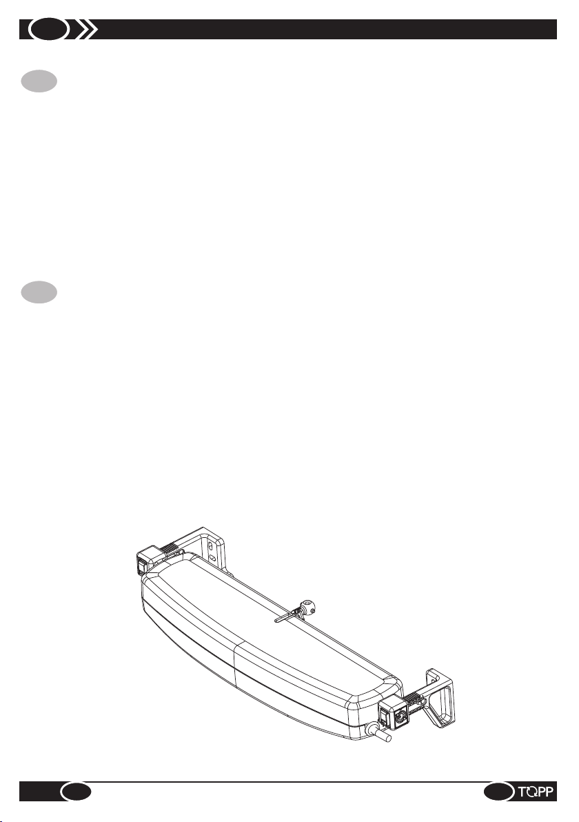
8
FIGURE / FIGURES
IT
DENOMINAZIONE DEI COMPONENTI E DIMENSIONI. . . . . . . . . . . . . . . . . . . . . . . . . . . . . . . . . . . pag 24
FORMULE PER IL CALCOLO DELLA FORZA DI SPINTA O TRAZIONE . . . . . . . . . . . . . . . . . . . . . pag 26
TARGA PER LA SICUREZZA . . . . . . . . . . . . . . . . . . . . . . . . . . . . . . . . . . . . . . . . . . . . . . . . . . . . . . . . pag 26
CONFEZIONE . . . . . . . . . . . . . . . . . . . . . . . . . . . . . . . . . . . . . . . . . . . . . . . . . . . . . . . . . . . . . . . . . . . . pag 27
APPLICAZIONE PER FINESTRE CON APERTURA A SPORGERE . . . . . . . . . . . . . . . . . . . . . . . . pag 28
APPLICAZIONE PER FINESTRE CON APERTURA A VASISTAS . . . . . . . . . . . . . . . . . . . . . . . . . . pag 31
MANOVRE DI EMERGENZA . . . . . . . . . . . . . . . . . . . . . . . . . . . . . . . . . . . . . . . . . . . . . . . . . . . . . . . . pag 36
SCHEMI PER IL COLLEGAMENTO ELETTRICO. . . . . . . . . . . . . . . . . . . . . . . . . . . . . . . . . . . . . . . . pag 37
EN
NAME OF COMPONENTS AND DIMENSIONS. . . . . . . . . . . . . . . . . . . . . . . . . . . . . . . . . . . . . . . . . . pag 24
FORMULAS TO CALCULATE THRUST FORCE OR TRACTION FORCE . . . . . . . . . . . . . . . . . . . . pag 26
SAFETY PLATE . . . . . . . . . . . . . . . . . . . . . . . . . . . . . . . . . . . . . . . . . . . . . . . . . . . . . . . . . . . . . . . . . . . pag 26
PAKAGE. . . . . . . . . . . . . . . . . . . . . . . . . . . . . . . . . . . . . . . . . . . . . . . . . . . . . . . . . . . . . . . . . . . . . . . . . pag 27
APPLICATION FOR TOP HUNG WINDOWS . . . . . . . . . . . . . . . . . . . . . . . . . . . . . . . . . . . . . . . . . . . . pag 28
APPLICATION FOR BOTTOM HUNG WINDOWS . . . . . . . . . . . . . . . . . . . . . . . . . . . . . . . . . . . . . . . pag 31
EMERGENCY PROCEDURES . . . . . . . . . . . . . . . . . . . . . . . . . . . . . . . . . . . . . . . . . . . . . . . . . . . . . . . pag 36
LAYOUTS FOR ELECTRICAL CONNECTIONS . . . . . . . . . . . . . . . . . . . . . . . . . . . . . . . . . . . . . . . . . pag 37
INDICE FIGURE
FIGURE INDEX
C25
!
FIGURE / FIGURES
23

DENOMINAZIONE DEI COMPONENTI
IT
E DIMENSIONI
2a
Fig.
Dimensioni in mm / Dimensions in mm
10
117.5
107
3
NAME OF COMPONENTS AND
EN
DIMENSIONS
56
Ø4.5
1
14
4.5
34
16
7
46
16
17
91
LEGENDA
IT EN
1. Staffa per apertura “vasistas”
2. Attacco rapido
3. Pulsante di sgancio del terminale catena
24
FIGURE / FIGURES
2
18
LEGEND
1. Bracket for bottom hung window
2. Quick coupling
3. Button to release the chain terminal
!
C25

Fig.
2b
Dimensioni in mm / Dimensions in mm
372
115
7
12.512.5
2
3
67
56
1
2
290.4
324.4
4
47
40
6
49
LEGENDA
IT EN
1. Attuatore C25
2. Terminale catena
3. Staffa di attacco al serramento DX
4. Staffa di attacco al serramento SX
5. Cavo di alimentazione elettrica
6. Regolazione corsa di apertura switch
I=200mm; II=380mm.
!
C25
5
6
LEGEND
1. Actuator C25
2. Chain terminal
3. Fitting bracket - right Hand
4. Fitting bracket - left hand
5. Power supply cable
6. Adjusting opening stroke (via limit switch)
I=200mm; II=380mm.
25
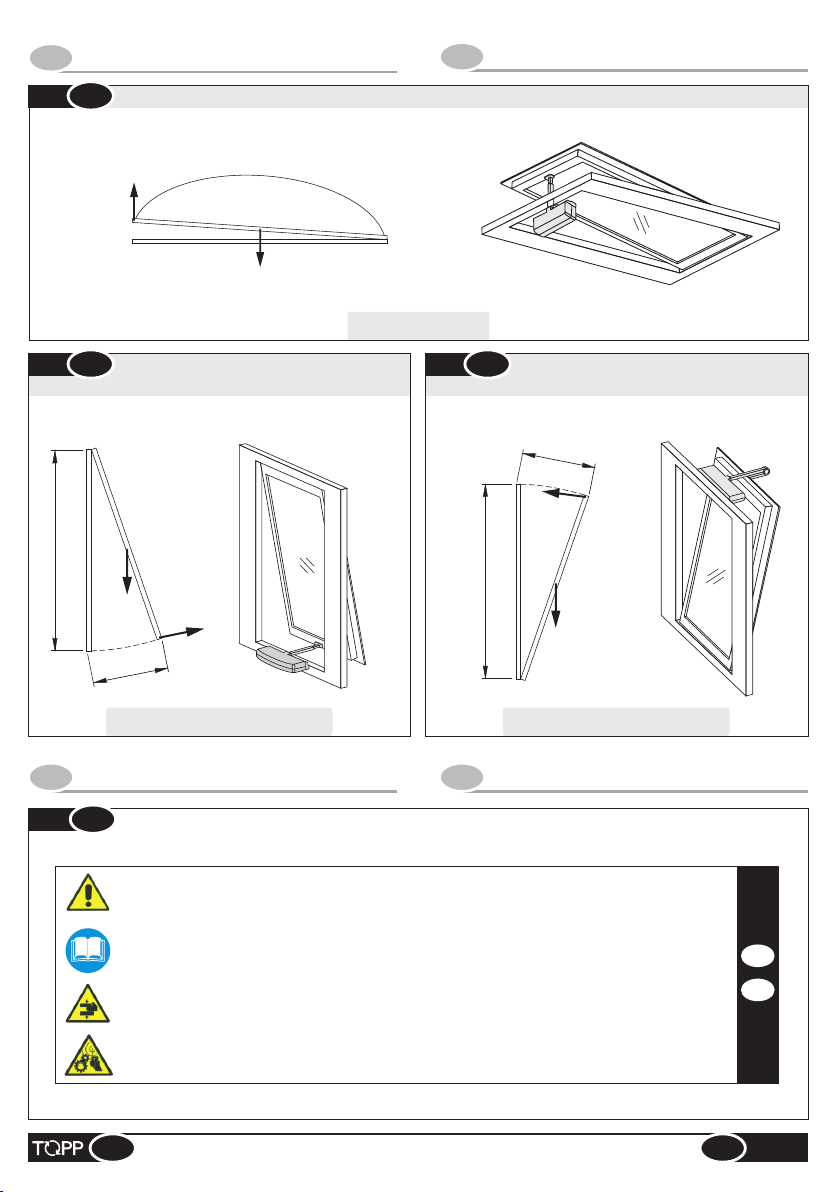
FORMULE PER IL CALCOLO DELLA
IT
FORZA DI SPINTA O TRAZIONE
Finestre con apertura a cupola / Windows with dome opening
3
Fig.
F
P
EN
F = (0,54 x P)
FORMULAS TO CALCULATE THRUST
FORCE OR TRACTION FORCE
4
Fig.
Finestre con apertura a sporgere
Windows with top hung opening
H
P
C
F = (0,54 x P) x (C / H)
TARGA DI SICUREZZA
IT
Fig.
6
MACCHINA AD AVVIA MENTO AUTOM AT ICO
AUTOM ATIC MA CHINE
PRIMA DI INSTAL LARE E UTIL IZZARE L'ATTU AT ORE È OBB LIGATORIO CHE L'INSTAL LATORE E L'U TILIZZATORE
LEGGANO E COM PRENDANO IN TUTTE LE SU E PARTI IL MAN UALE
THE I NSTALLER AND USER MUST READ AND UN DERSTAND ALL PA RTS OF THI S MANUA L BEFORE I NSTALLIN G AND
USIN G THE ACT UATOR.
PERICOLO ATTEN ZIONE ALLE MANI
BEWARE OF YOUR HANDS
ATTENZIONE MACCH INA AD AVVI AMENTO AUTOMATIC O CO N COMANDO A DISTANZA
ATTENT ION! AUTOMATIC MACH INE WITH REMOTE CONT ROL DEVICE
5
Fig.
Finestre con apertura a vasistas
Windows with bottom hung opening
C
F
H
F
P
F = (0,54 x P) x (C / H)
SAFETY PLATE
EN
IT
EN
26
FIGURE / FIGURES
!
C25
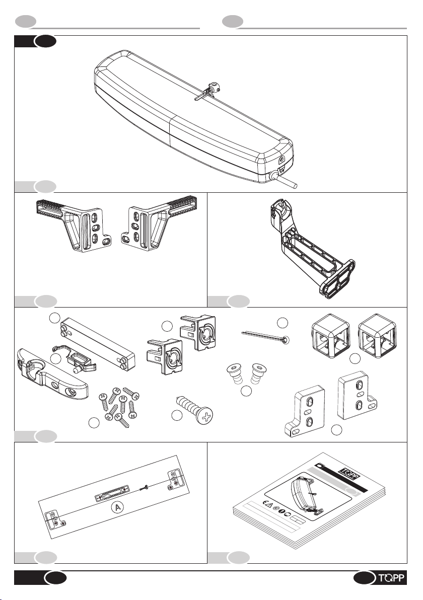
CONFEZIONE
IT
Fig.
A
Rif.
PAKAGE
EN
7
Rif.
Rif.
Rif.
C25
B
2
3
1
Rif.
C
7
9
6
4
D
E
!
5
F
Rif.
FIGURE / FIGURES
PRIMA
DI INSTALLARE
IL PRESENTE MANUALE
LEGGANO E COMPRENDANO
CONSERVATO PER FUTURI RIFERIMENTI FINO
È
8
IT
I
S
T
RU
Z
IO
A
TT
N
I
UATORE A C
AUTO
P
E
R L’
M
IN
AZI
STA
ON
ATENA
L
E
L
AZIO
FINESTR
P
NE
ER
E L'
E
US
C25
BREVETTATO
E UTILIZZARE L
PARTE
’
APPARECCHIO
INTEGRANTE DELL
IN
TUTTE
È OBBLIGATORIO
LE
SUE
COD
’
APPARECCHIO E
VER
PARTI
. 8P5270
CHE
0.0
IL
ALLA DEMOLIZIONE
L
PRESENTE
’INSTALLATORE E L’UTILIZZATORE
REV 09.08
DEVE OBBLIGATORIAMENTE ESSERE
MANUALE
DELLO STESSO.
.
O
27

APPLICAZIONE PER FINESTRE A SPORGERE
IT
8
Fig.
Quota D variabile da 0 a 20mm
D
Dimension D variable from 0 to 20 mm
APPLICATION FOR TOP HUNG WINDOWS
EN
IT
ANTA
WING
13±1
113
49
D
Quota D variabile da 20 a 30mm
Dimension D variable from 20 to 30 mm
93
ANTA
1
WING
13±1
A
27
34
TELAIO
FRAME
2
A
49
NOTE
27
34
NOTES
EN
@ La posizione di fissaggio “A” va
ver ifi cat a e va luta ta i n bas e al
profilo/larghezza dell’anta/ telaio e luce
finestra.
@ Per finestre aventi “luce finestra”
inferiore a 500mm si consigli a di
regolare la corsa a 200mm (switch in
posizione I).
SORMONTO “D”
0 20 mm÷
20 30 mm÷
RIF APPLICAZIONE
Attacco rapido
1
Attacco rapido +
2
distanziale
28
TELAIO
FRAME
FIGURE / FIGURES
@ Fastening position “A” should be
checked and considered according to
the profile/width of the window leaf/
frame and window light.
@ For windows with “window light” less
than 500mm, we recommend adjusting
the stroke to 200mm (switch in position
I).
OVERLAPPED
PART “D”
0 20 mm÷
20 30 mm÷
REF APPLICATION
Quick coupling
1
Quick coupling
2
+ spacer
!
C25

Fig.
9
X
Fig.
10
Fig.
Fig.
11
13
Fig.
12
coppia di serraggio delle viti M6 = 2,5Nm
IT
screw M6 tightening torque = 2,5Nm
EN
!
C25
FIGURE / FIGURES
29
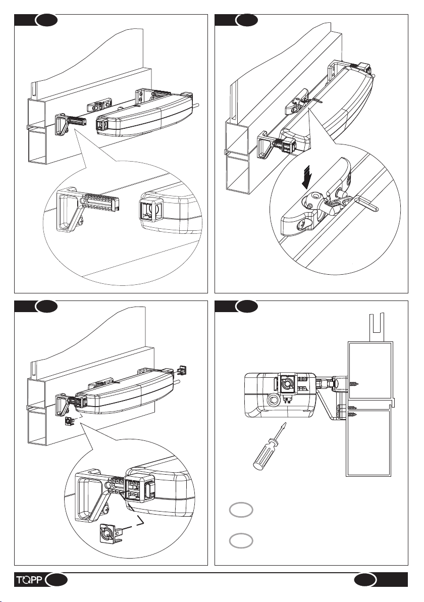
Fig.
14
Fig.
15
Fig.
16
30
Fig.
IT
EN
FIGURE / FIGURES
17
switch in posizione I = corsa 200mm
switch in posizione II = corsa 380mm
switch under position I = stroke 200mm
switch under position I = stroke 380mm
!
C25
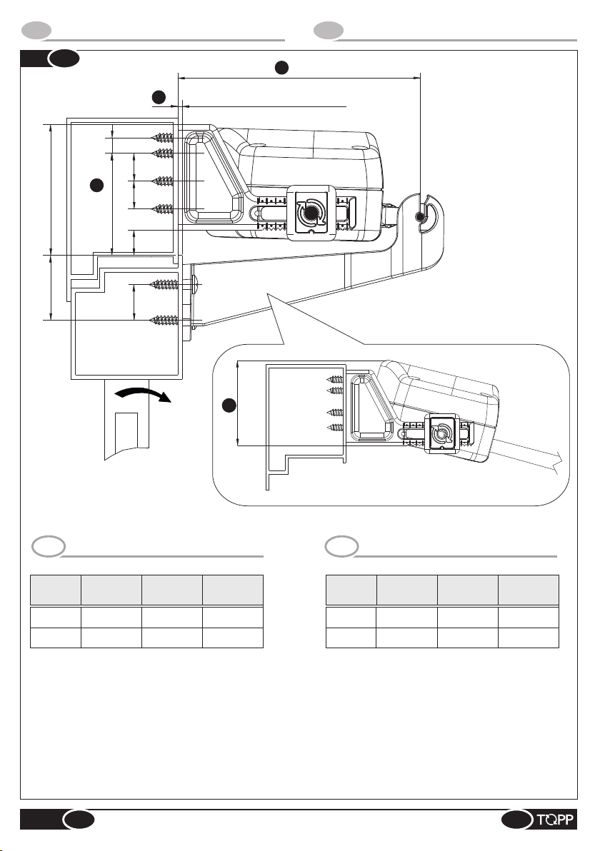
APPLICAZIONE PER FINESTRE A VASISTAS
IT
18
Fig.
Quota D variabile da 0 a 10mm
D
Dimension D variable from 0 to 10 mm
7
12,5
59,5
A
TELAIO
FRAME
46,5
12,5
12
APPLICATION FOR BOTTOM HUNG WIN DOWS
EN
C
109
28,5
NOTE
IT EN
Corsa
200mm
380mm
@ La quota “A” va verificata e valutata in base al
profilo/larghezza dell’anta/ telaio e luce finestra ;
@ La posizione di fissaggio “C” è compresa tra 99 e
109mm;
@ La quota “D” deve essere compresa tra 0 ÷ 10mm.
@ Qualora l’attuatore venisse tarato con corsa
380mm, assicurarsi che, durante l’azionamento del
motore, la catena non vada a toccare il serramento.
In questo caso regolare la corsa a 200mm.
16
ANTA
WING
Luce Min.
Finestra
Angolo
Apertura
Ingombro
Motore “B”
350mm 35° 61mm
1000mm
21°
54mm
B
TELAIO
FRAME
NOTES
Stroke
200mm
380mm
@ Dimension “A” should be verified and considered
according to profile/width of the window wing/ frame
and window light ;
@ Fixing position “C” is between 99 and 109mm;
@ Dimension “D” must be between 0 ÷ 10mm.
@ If the actuator is set with a stroke of 380mm, make
sure that the chain does not touch the window when
the motor is running. In this case, adjust the stroke
to 200mm.
Window
min. light
350mm 35° 61mm
1000mm
Opening
angle
21°
Motor “B”
size
54mm
C25
!
FIGURE / FIGURES
31

Fig.
18a
59,5
A
7
46,5
12,5
12,5
12
Quota D variabile da 10 a 20mm
D
Dimension D variable from 10 to 20 mm
132
C
28,5
NOTE
IT EN
@ La quota “A” va verificata e valutata in base al
profilo/larghezza dell’anta/ telaio e luce finestra ;
@ La posizione di fissaggio “C” è compresa tra 117 e
132mm;
@ La quota “D” deve essere compresa tra 10 ÷ 20mm.
Fissare le staffe di attacco al telaio della finestra
utilizzando i distanziali di spessoramento contenuti
nella confezione minuteria (Fig.7 Rif.D-9);
@ Qualora l’attuatore venisse tarato con corsa
380mm, assicurarsi che, durante l’azionamento del
motore, la catena non vada a toccare il serramento.
In questo caso regolare la corsa a 200mm.
16
NOTES
@ Dimension “A” should be verified and considered
according to profile/width of the window wing/ frame
and window light ;
@ Fixing position “C” is between 117 and 132mm;
@ If the overlapped part “D” be included between 10
and 20mm, the brackets have to be fitted by using
the supplied appropriate shims (Fig.7 Rif.D-9);
@ If the actuator is set with a stroke of 380mm, make
sure that the chain does not touch the window when
the motor is running. In this case, adjust the stroke
to 200mm.
32
FIGURE / FIGURES
!
C25

Fig.
Fig.
19
21
Fig.
20
Y
Fig.
C25
22
coppia di serraggio delle viti M6 = 2,5Nm
IT
screw M6 tightening torque = 2,5Nm
EN
!
FIGURE / FIGURES
33

Fig.
Fig.
23
25
Fig.
24
34
FIGURE / FIGURES
!
C25

Fig.
26
Fig.
C25
27
switch in posizione I = corsa 200mm
IT
switch in posizione II = corsa 380mm
!
EN
FIGURE / FIGURES
switch under position I = stroke 200mm
switch under position I = stroke 380mm
35
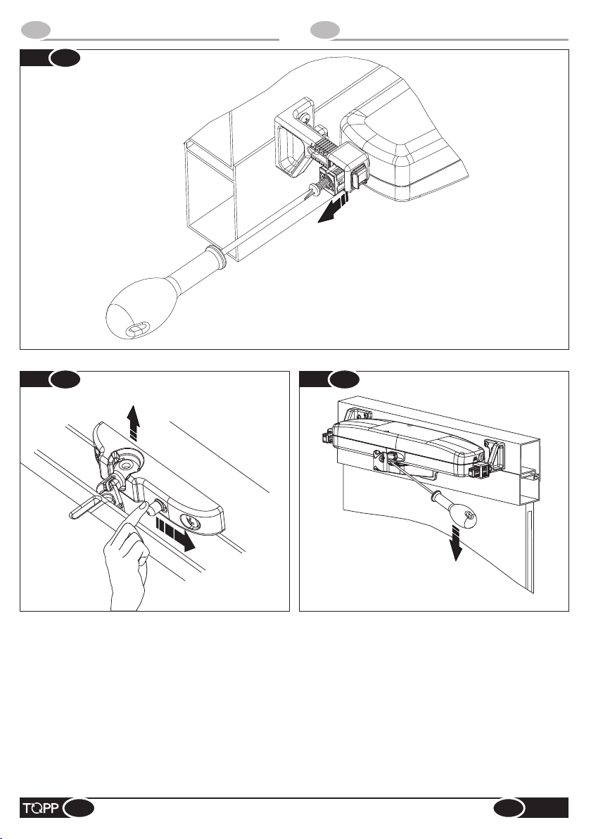
MANOVRE DI EMERGENZA
IT
Fig.
28
EMERGENCY PROCEDURES
EN
Fig.
29
Fig.
30
36
FIGURE / FIGURES
!
C25

SCHEMI PER IL COLLEGAMENTO ELETTRICO
IT
Fig.
31
LAYOUTS FOR ELECTRICAL CONNECTIONS
EN
N
230V~50Hz
L
C25
A
C25 C25
A
MARRONE / BROWN
NERO / BLACK
MARRONE / BROWN
NERO / BLACK
GRIGIO / GRAY
A
CHIUDE
CLOSE
APRE
OPEN
230V~50Hz
CHIUDE
CLOSE
N
L
GRIGIO / GRAY
C25
A
?
QUESTO SIMBOLO IDENTIFICA NEGLI SCHE MI DI COLLEGAMENTO
IT
ELETTRICO L’ATTUATORE TOPP SRL.
TH IS SY MBO L I DE NT IF IE S T HE ACTUATOR TOP P SRL I N TH E
EN
ELECTRICAL CONNECTION LAYOUTS.
NOTE / NOTES
APRE
OPEN
37

NOTE
38
NOTE / NOTES
?
C25


TOPP S.r.l.
Società a Socio Unico soggetta a direzione e coordinamento di 2 Plus 3 Holding S.p.a.
Via Galvani, 59 - 36066 Sandrigo (VI) - Italia
Tel. +39 0444 656700 - Fax +39 0444 656701
Info@topp.it - www.topp.it
 Loading...