

ORIGINAL
INSTALLATION AND USE INSTRUCTIONS
CHAIN ACTUATOR FOR
WINDOW AUTOMATION
C20
PATENTED
COD. 0P5186
VER.0.0 REV.09.13
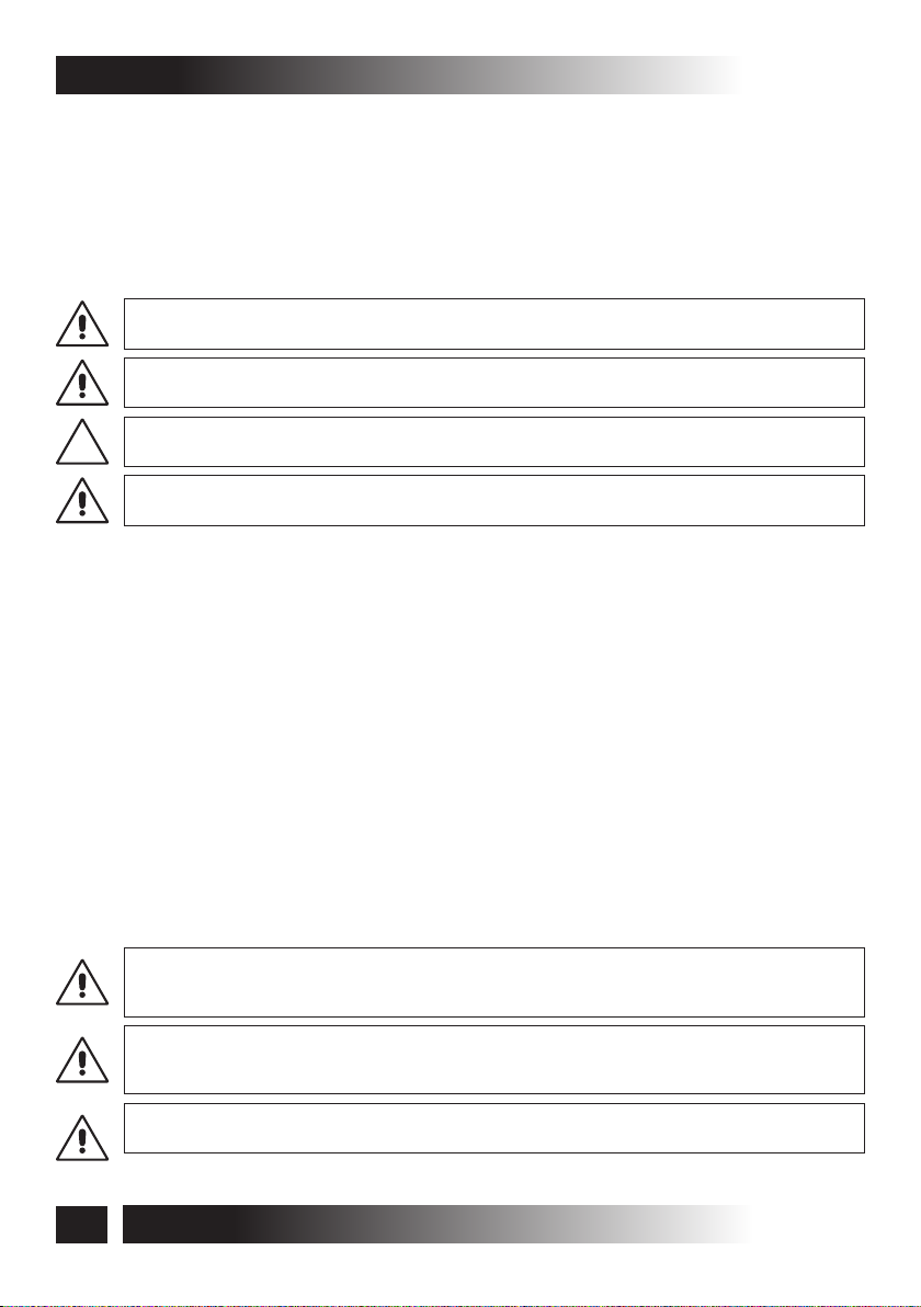
BEFORE INSTALLING AND USING THE ACTUATOR, IT IS
COMPULSORY FOR THE INSTALLER AND THE USER TO READ
AND UNDERSTAND THIS MANUAL IN ALL ITS PARTS.
THIS MANUAL IS INTEGRAL PART OF THE ACTUATOR
AND MUST BE PRESERVED FOR FUTURE REFERENCE
UNTIL DEMOLITION OF THE SAME.


C20
INDEX
1- DECLARATION OF “CE” CONFORMITY
........................................................................................................................page 04
2- GENERAL REMARKS
2.1- General instructions..........................................................................................page 05
2.2- Installer and user..............................................................................................page 05
2.3- Warranty...........................................................................................................page 05
2.4- Technical assistance.........................................................................................page 05
2.5- Reserved rights ................................................................................................page 05
2.6- Description of personnel...................................................................................page 06
3- TECHNICAL DESCRIPTION
3.1- Rating plate and “CE” marking .........................................................................page 07
3.2- Denomination of the components and dimensions ..........................................page 08
3.3- Technical data...................................................................................................page 10
3.4- Formulas for the calculation of thrust force or tractive force.............................page 11
3.5- Destination of use.............................................................................................page 11
3.6- Use Limits.........................................................................................................page 12
3.7- Package ...........................................................................................................page 12
4- SAFETY
4.1- General instructions .........................................................................................page 14
4.2- Safety Devices .................................................................................................page 14
4.2.1- Protections against electric hazard .......................................................page 14
4.3- Safety plates.....................................................................................................page 15
4.4- Residual risks ...................................................................................................page 15
5- INSTALLATION
5.1- General instructions .........................................................................................page 16
5.2- Top hung windows ............................................................................................page 20
5.3- Bottom hung windows ......................................................................................page 21
Dome windows
5.4- .................................................................................................page 22
5.5- Electrical Connections......................................................................................page 24
5.6- Control devices.................................................................................................page 24
5.7- Correct assembly of the actuator on the window frame ...................................page 25
5.8- Emergency procedures ....................................................................................page 26
6- USE AND OPERATION
6.1- Use of the actuator ...........................................................................................page 27
7- MAINTENANCE
7.1- General instructions .........................................................................................page 28
8- DEMOLITION
8.1- General instructions .........................................................................................page 28
9- SPARE PARTS AND ACCESSORIES UPON REQUEST
9.1- General instructions .........................................................................................page 29
9.2- Brackets for vertical assembly..........................................................................page 29
Quick coupling with integrated release push-button ARP
9.3- “ ”..............................page 30
Dome windows
9.3.1- ......................................................................................page 30
9.3.2- Emergency procedures .........................................................................page 31
FIGURES
........................................................................................................................page 32
CERTIFICATE OF GUARANTEE
........................................................................................................................page 39
VER.0.0
REV.09.13
INSTALLATION AND USE ISTRUCTIONS
3

1- DECLARATION OF “CE” CONFORMITY
TOPP S.p.A.
via L. Galvani, 59
36066 Sandrigo (VI)
ITALIA
declares that the electrical device
called: CHAIN ACTUATOR FOR WINDOW AUTOMATION
type: C20
models: C20/230V - C20/24V
Serial n° and year of manufacture: see data plate and CE marking applied to
the device
complies with the requirements of the following directives:
2006/95/CE
Low Voltage Directive: electrical material for use within certain voltage limits.
2004/108/CE
Electromagnetic Compatibility Directive - Concerning the approximation of the laws of
Member States relating to electromagnetic compatibility.
C20
and also declares that the following harmonised standards have been applied:
EN55014-1
EN55014-2
EN61000-6-3
EN61000-6-2
EN50366
EN60335-1
Date: Sandrigo, 10/01/2008
Matteo Cavalcante .....................................................
INSTALLATION AND USE INSTRUCTIONS
4
VER.0.0
REV.09.13
C20
GENERAL REMARKS -2
2.1- GENERAL INSTRUCTIONS
BEFORE INSTALLING AND USING THE ACTUATOR, IT IS COMPULSORY THAT THE
INSTALLER AND THE USER CAREFULLY READ AND UNDERSTAND THIS MANUAL IN
ALL ITS PARTS.
THIS MANUAL IS INTEGRAL PART OF THE ACTUATOR AND MUST COMPULSORILY BE
PRESERVED FOR FUTURE REFERENCE.
THE MANUFACTURER HAS NO LIABILITY FOR ANY EVENTUAL DAMAGE TO PERSONS,
ANIMALS AND THINGS DUE TO THE INOBSERVANCE OF THE PRESCRIPTIONS
DESCRIBED IN THIS MANUAL.
2.2- INSTALLER AND USER
THE ACTUATOR INSTALLATION CAN BE PERFORMED EXCLUSIVELY BY COMPETENT
AND QUALIFIED TECHNICAL PERSONNEL SATISFYING THE PROFESSIONAL AND
TECHNICAL REQUIREMENTS FORESEEN BY THE LAWS IN FORCE IN THE COUNTRY OF
INSTALLATION.
THE ACTUATOR CAN BE USED EXCLUSIVELY BY A USER ACTING IN COMPLIANCE WITH
THE INSTRUCTIONS CONTAINED IN THIS MANUAL AND/OR IN THE MANUAL OF THE
ACTUATOR CONTROL DEVICE (E.G.: CONTROL UNIT).
2.3- WARRANTY
THE ACTUATOR WARRANTY EXPIRES, IF ITS USE DOES NOT COMPLY WITH THE
INSTRUCTIONS AND PRESCRIPTIONS DESCRIBED IN THIS MANUAL, AS WELL AS IF
NON-ORIGINAL COMPONENTS, ACCESSORIES, SPARE PARTS, AND CONTROL
SYSTEMS ARE USED.
2.4- TECHNICAL ASSISTANCE
For the technical assistance apply to your Dealer or to the Manufacturer.
2.5- RESERVED RIGHTS
The reserved rights on this manual "Installation and use instructions" remain property of
the Manufacturer.
Each information herein contained (text, drawings, diagrams, etc.) is reserved.
None part of this manual can be reproduced and disclosed (totally or partially) by any
reproduction means (photocopies, microfilms or other) without written authorization of
the Manufacturer.
VER.0.0
REV.09.13
INSTALLATION AND USE INSTRUCTIONS
5

2- GENERAL REMARKS
2.6- DESCRIPTION OF PERSONNEL
USERS MUST NEVER PERFORM OPERATIONS RESERVED FOR MAINTENANCE
PEOPLE OR SPECIALISED TECHNICIANS. THE MANUFACTURER DECLINES ALL
LIABILITY FOR DAMAGE DERIVING FROM FAILURE TO OBSERVE THE ABOVE
REQUIREMENTS.
Specialised electrician:
A specialised electrician must be able to install the actuator, start it and operate it both
in normal conditions and in the maintenance mode; he/she is qualified to perform all
electrical and mechanical adjustment and maintenance operations. He/she is allowed
to work on live electrical cabinets and junction boxes.
User:
specialised person capable of operating the actuator under normal conditions by using
the relative controls. He/she must also be able to operate with the actuator under
“maintenance” in order to perform simple routine maintenance operations (cleaning),
and start or reset the actuator following an unscheduled stop.
C20
6
INSTALLATION AND USE ISTRUCTIONS
VER.0.0
REV.09.13

C20
TECHNICAL DESCRIPTION -3
3.1- RATING PLATE AND “CE” MARKING
The “CE” marking certifies the compliance of the machine with the essential safety and
health requirements foreseen by the product European Directives.
The rating plate is an adhesive plate in polyester, silk-screen printed in black, having the
following size: L=36 mm - H=50 mm.
It is applied externally on the actuator. The plate (Fig. 1) bears in readable and indelible
way the following data:
• logo and address of the manufacturer
• type and model
• voltage and intensity of power supply (V - A)
• absorbed electric power P (W)
• thrust and tractive force F (N)
• type of service S (min)
• idle translation speed (mm/s)
• protection degree (IP)
• “CE” marking
• symbol of WEEE Directive 2002/96/CE
• symbol of double insulation (only for mod. C20/230V)
• serial number
2
VER.0.0
REV.09.13
Fig. 1
Sandrigo - made in Italy
N:0910TA12000
Sandrigo - made in Italy
N:0910TA12000
INSTALLATION AND USE ISTRUCTIONS
C20
230V~ 50Hz
I = 0,12A
P = 25W
F = 300N
S2 = 4min
8 mm/s
IP30
C20
24V
I = 0,43A
P = 9W
F = 300N
S2 = 4min
7,5 mm/s
IP30
7
3- TECHNICAL DESCRIPTION
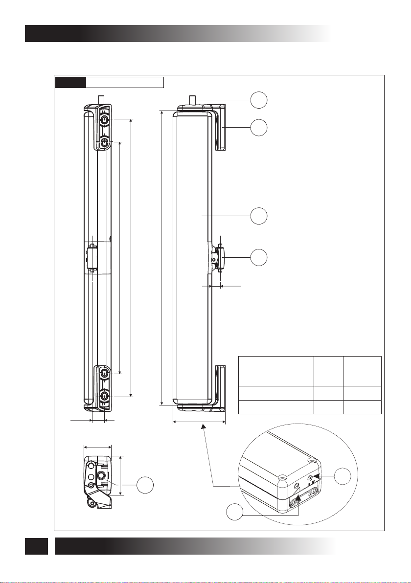
3.2- DENOMINATION OF THE COMPONENTS AND DIMENSIONS
C20
Fig. 2a
Dimensions in mm
342
286
1
2
3
362
4
10.3
LEGEND:
1) Power supply cable
2) Window frame connection brackets (right-left)
3) Actuator
4) Chain end
5) Electric connector
6) Switch I=240 mm; II=360 mm
15.1
34
48
5
INSTALLATION AND USE INSTRUCTIONS
8
64.5
Dip switch power
7)
7
Min
(-)
Max
(+)
Thrust
force
150 N
300 N
Tractive
force
100 N
200 N
6
+
-
VER.0.0
REV.09.13

C20
TECHNICAL DESCRIPTION -3
Fig. 2b
42
Dimensions in mm
.5
10
80
27
11
2
1
8615
3
4
17
42
11
15
8.4
14
16
5
36
15
51.8
13.313
(43)
30
9.5
2.5
85
VER.0.0
REV.09.13
LEGEND:
1) Bracket for bottom hung opening
Quick coupling to the window frame “ARS”
2)
3) Release side indicator
4) Bracket for vertical assembly “A”
5) Bracket for vertical assembly “B”
INSTALLATION AND USE ISTRUCTIONS
19.5
2
3
16.8
35
24±0,1
17.5
2
(4)
9
3- TECHNICAL DESCRIPTION
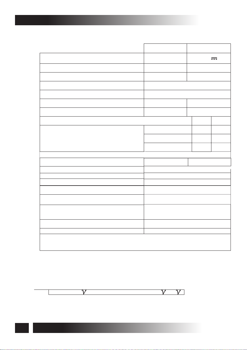
3.3- TECHNICAL DATA
Tab. 1 contains the technical data characterising the actuators.
Tab. 1
Power supply voltage
Absorbed current
Absorbed power with load
Thrust force
Tractive force
Idle translation speed
Duration of the idle stroke (360 mm)
Operation stroke length (mm)
Minimum window
frame height (mm)
(2)
Limit switch: Electronic for opening - by amperometric absorption for closing.
Protection against electric shock
Type of service S
(3)
2
Operating temperature
Protection degree of electric devices
Adjustment of the window frame connection
Parallel electric connection of more
actuators on the same window
Parallel electric connection of more
actuators on different windows
Actuator weight with brackets
Gross weight
(1)
Tolerance on the precision of limit switch tripping at output: +/- 2 cm.
(2)
Actuator distance from the window frame opening hinge
(3)
Service of limited duration according to EN 60034
(1)
C20/230V
230 V - 50 Hz
0,12 A
25 W
8 mm/s
46 s
Top hung
Bottom hung
Dome
Classe II
- 5 + 50 ºCºC
(see wiring diagram)
300 N
200 N
4 min
IP 30
NO
NO
Yes
0,97 kg
1,15 kg
C20/24V
24 V
0,43 A
9 W
7,5 mm/s
48 s
240
250
500
300
Classe III
C20
360
360
900
400
Compatibility of actuators connected in parallel
ACK4 T50 C20 C25 C30 C40 SL60 T80 C240 C20T
C20
10
INSTALLATION AND USE INSTRUCTIONS
VER.0.0
REV.09.13
C20
TECHNICAL DESCRIPTION -3
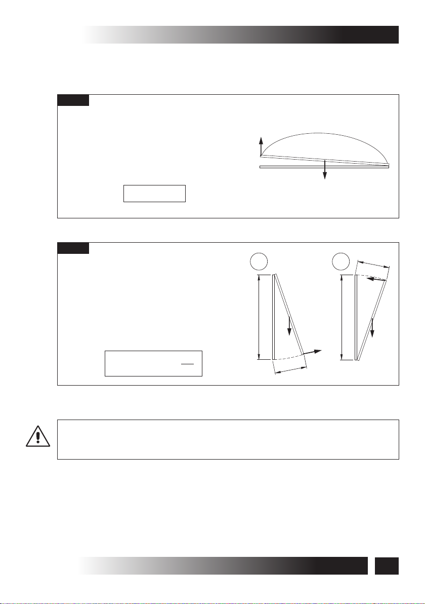
3.4- FORMULAS FOR THE CALCULATION OF THRUST AND TRACTIVE
FORCE
Fig. 3
Horizontal domes or skylights
F= Force necessary for opening or
closing
P= Weight of the skylight or dome
(Only movable part)
F = 0.54 x P
Fig. 4
Top hung windows (A) or
bottom hung windows (B)
F = Force necessary for opening or
closing
P = Weight of the window
(Only movable part)
C = Window opening stroke
H = Window height (Only movable part)
F = (0.54 x P) x ( )
C
H
F
P
A
H
P
C
B
H
F
C
F
P
3.5- DESTINATION OF USE
THE ACTUATOR HAS BEEN DESIGNED AND MANUFACTURED TO PERFORM
AUTOMATICALLY, BY MEANS OF A COMMAND DEVICE, THE OPENING AND CLOSING
OF TOP HUNG WINDOWS, BOTTOM HUNG WINDOWS, PIVOT WINDOWS, AND
SKYLIGHTS.
VER.0.0
REV.09.13
INSTALLATION AND USE ISTRUCTIONS
11
3- TECHNICAL DESCRIPTION
3.6- USE LIMITS
The actuator has been designed and manufactured exclusively for the destination of
use given in par. 3.5, therefore, any other type of use is strictly forbidden in order to
assure in any moment the safety of the installer and of the user, as well as the efficiency
of the actuator itself.
IT IS STRICTLY FORBIDDEN TO USE THE ACTUATOR FOR IMPROPER USES, I.E. OTHER
THAN THE ONE FORESEEN BY THE MANUFACTURER (SEE PAR. 3.5).
IT IS STRICTLY FORBIDDEN TO INSTALL THE ACTUATOR ON THE EXTERNAL SIDE OF
THE WINDOW FRAME SUBJECT TO ATMOSPHERIC AGENTS (RAIN, SNOW, ETC.).
THE USE OF THE ACTUATOR IN ENVIRONMENTS WITH POTENTIALLY EXPLOSIVE
ATMOSPHERE IS STRICTLY FORBIDDEN.
EX
IT IS COMPULSORY TO KEEP THE PACKAGE AND THE ACTUATOR OUT OF REACH OF
CHILDREN.
3.7- PACKAGE
Each package of the product (cardboard box) contains (Fig. 5):
• No. 1 Actuator equipped with power supply cable (with electric connector);
• No. 2 Window frame connection brackets (right-left) (Ref. A);
• No. 1 Bracket for bottom hung opening (Ref. B);
• No. 1 Adhesive drilling template (Ref. C);
• No. 1 Small parts package for aluminum windows (No. 2 screws for lateral fastening of
connection brackets to the window, No. 7 screws AF Ø 4,8 x 16 mm and No. 2 screws
AF Ø 4,2 x 19 mm for the fastening of the brackets to the window frame and for ARS
coupling fastening) (Ref. D);
• No. 1 ARS coupling release tool (Ref. D-1);
• No. 1 ARS coupling (Ref. D-2);
• No. 1 Installation and use instructions (Ref. E);
• No. 1 Safety plate (Fig. 6);
C20
MAKE SURE THAT THE ABOVE DESCRIBED COMPONENTS ARE CONTAINED IN THE
PACKAGE, AS WELL AS THAT THE ACTUATOR HAS NOT BEEN DAMAGED DURING
TRANSPORT.
SHOULD ANY ANOMALY BE DETECTED, IT IS FORBIDDEN TO INSTALL THE ACTUATOR,
AND IT IS COMPULSORY TO REQUIRE TECHNICAL ASSISTANCE FROM YOUR DEALER
OR THE MANUFACTURER.
THE PACKAGING (PAPER, PLASTIC, ETC.) HAS TO BE DISPOSED ACCORDING TO THE
LAWS IN FORCE.
12
INSTALLATION AND USE INSTRUCTIONS
VER.0.0
REV.09.13

C20
TECHNICAL DESCRIPTION -3
Fig. 5
A
8
.
3
.8
3
Ø
O
T
NA
T
I
A
N
M
RS
NT
LI
I
E
ME
E
R
.8
Ø3
ÂT
V
IO
B
NST
A
RRA
E
L
E
DU
S F
D
INFER
E
EL SE
R
A
D
'S
ISS
URE
O
F
E
RT
E
E
O PA
T
MEN
A
RR
NA SE
IXE
F
TER
'S
N
W
I
O
EA
IN
L
WIND
F
INE O
EN F
L L
TZ
NA
SE
E
G
INTER
ST
FE
S
E
D
IE
TRE
IN
E
N
NL
E
FE
N
E
IN
E D
R
IEU
ER
T
A
N
E I
IGN
L
E LA VENT
IOR D
ER
NT
I
LINEA
3.8
RE
E
G
R
G
O A SPO
T
FNUN
N
F
E
E
O
N
RAM
R
TE
E
UN
R S
IT
M
PE
A
ER
T
SIV
S
E
N
D
W
E
A
F
A
DO
IM
ER
D
FU
E
N
O
L
INGED WIN
H
AB
P
AR
CH
T
L
BS
O TO
SA
T
LE
E
K
T
RE
A
A
A
PL
M
E
TAN
T
N
E
IVE
V
A
ES
R
DH
C
A
E
SIVA PA
ROJ
E
H
P
A
E
AD
A
R
L
ET
TIL
AN
FEN
PL
OUR
P
IF
ES
H
D
A
IT
GABAR
.8
3
Ø
3.8
Ø
L
GE
A
CAL
I
CA
I
T
T
NT
R
NTING
R
E
U
MO
VE
VE
AL
E
MO
E
JE
T
IC
3.8
Ø
CH
TAG
CAL
ERT
I
T
V
ON
MONTA
R
A
M
VE
R
R
GGIO
SENKRE
U
PA
OR
.8
NTA
F
VA
3
I
F PO
O
I
Ø
FUER
M
S
ES
E
LATE
NE
H
P
ER
DH
M
LO
P
AD
E
B
A
T
T
IV
LLA A
E
RI
CHA
V
TI
I
S
BA
.8
DES
A
ES
A
EB
LAN
G
H
P
KL
MA
I
AD
D
E
F
AF
T
NE S
IO
SIZ
O
P
IT
S
O
S P
KET
BRAC
IENTO D
M
A
ION
POSIT
ER
N D
SITIO
O
P
DES ET
N
IO
IT
POS
.8
3
Ø
Ø3.8
Ø3
AS
T
ASIS
V
ING
T
A
N
GIO
OU
G
A
DOW M
MONT
A
R
T
E
WIN
D
AL
P
GE
HIN
UELLE
E F
OM
D
A
N
TA
O BOTT
T
N
VEN
IO
A
R
A
R
TE
NS
E
ESTAFA P
PF
E LA
R KIP
FÜ
N
E
L
FLET
SO
F
N
U
O
O
A S
RE
ONTAGEK
ET
N
M
R FE
U
O
S P
R
RIE
RE
E
G
R
SPO
ING
GIO A
T
G
A
T
OUN
N
W M
R MO
O
D
R
FE PE
AF
SALTA
E
INGED WIN
E ST
N
A R
P H
O
NA
TA
O T
N
POSIZIO
E
N T
IO
A V
R
IT
A
R
P
OS
TE
S
FA
S P
TA
EN
KET
PF
ES
P
AC
BR
E LA
KLA
R
TO D
N
IEN
EN FÜ
L
CTIO
AM
SO
E
N
N
IO
OJ
O
R
P
POSIT
E A
R
ONTAGEK
NET
M
FE
ER
R
D
U
N
O
IO
P
IT
RS
IE
POS
R
ET
DES
N
IO
POSIT
.8
3
Ø
N
TIO
O
T
MEN
A
R
AL SER
CO
AC
OEC
TT
LB
E
I A
D
EG
E
U
FL
ASS
IK
T
AS
PL
R
E
D
E
S
H
IS
C
A
AX
'S
G
SIN
A
C
A
W
O
TAN
IND
EN
W
LA V
A
AJE
ET
FIS
E
EN
EJE D
A LA F
E
AG
ATTEL
DE
E
AX
ALE
IC
T
R
VE
GIO
G
A
ING
R MONT
E
E P
OUNT
F
AL
F
A
T
TIC
ICAL M
T
ER
ER
E V
V
R
SIZIONE S
TAJ
O
N
F
PO
O
M
ION
ARA
SIT
P
O
A
AF
ST
TAGE
ACKETS P
R
LA E
B
E MON
T
H
NTO DE
IE
KREC
NAM
N
ICAL
T
R SE
SITIO
O
P
E VER
FÜ
N
AG
T
N
POSITIO
R MO
U
EN
L
SO
S PO
N
IER
KO
R
T
N DES E
SITIO
O
P
Ø
N
E
H
KC
E
R
3.8
Ø
3
Ø
P
O
T
N
E
M
RA
NA SER
R
E
T
'S MO
W
IN
A
INE
L
WINDO
F
E O
L LIN
HEN
A
N
IC
L
ER
EG
INT
BEW
S
E
D
IE
IN
NT
E
ENL
V
N
A
IN
E L
D
R
ERIO
NE
INT
A
FE
INE
L
.8
3
RE DE
Ø
ERIEU
T
N
E I
LIGN
.8
RI
Z
ME
RI
RT
A
PA
D
FE
IORE D
R
FE
R
F
IN
S
E
IN
STER
GREN
EN
F
A
N
RTE MO
A
FE
ANA PARTE M
TRE M
E
E
T
E
I
NF
M
DOW
EE
IX
I
ER
E I
MIT
L
I
T
I
L
A
IJ
F
WIN
RTE
A
P
UNT
LIM
AS
T
IS
AS
V
A
TO
EN
M
RA
R
E
S
ER
ER
T
NS
E
SIVA P
E
PF
IP
AD
IND
K
R
IMA
D W
E
D
G
E FUE
IN
N
H
M
O
T
ABLO
T
O
B
UELLE AL
BSCH
E
TO
E
KL
AT
PL
TANA DE F
M
EN
L
V
F
A
IVE TE
S
AR
E
DH
A SOUF
A
IVA P
E
ES
TR
H
E
D
N
A
E
LA
R F
U
TIL
AN
PL
SIF PO
ADHE
IT
E
R
IL
B
BA
A
G
RT
A
P
G
IN
V
TERS
NS
OBIL
E
IL
B
O
Ø
8
Ø3.
.8
.8
3
Ø
3
.8
3
Ø
W
O
A
T
T
E
Ø
B
C
A
2
PATENTED
BEFORE INSTALLING AND USING THE ACTUATOR, IT IS
COMPULSORY FOR THE INSTALLER AND THE USER TO READ
AND UNDERSTAND THIS MANUAL IN ALL ITS PARTS.
THIS MANUAL IS INTEGRAL PART OF THE ACTUATOR
AND MUST BE PRESERVED FOR FUTURE REFERENCE
UNTIL DEMOLITION OF THE SAME.
INSTALLATION AND USE INSTRUCTIONS
CHAIN ACTUATOR FOR
C20
WINDOW AUTOMATION
COD. 0P5152
VER.0.0 REV.09.13
VER.0.0
REV.09.13
D E
INSTALLATION AND USE ISTRUCTIONS
13

4- SAFETY
GENERAL INSTRUCTIONS
4.1-
OPERATORS MUST BE INFORMED OF ACCIDENT RISKS, SAFETY DEVICES AND THE
GENERAL ACCIDENT PREVENTION REGULATIONS ESTABLISHED BY INTERNATIONAL
DIRECTIVES AND BY THE LAW IN FORCE IN THE COUNTRY OF USE.
ALL OPERATORS MUST STRICTLY COMPLY WITH THE ACCIDENT PREVENTION
REGULATIONS IN FORCE IN THE COUNTRY OF USE.
DO NOT REMOVE OR ALTER THE PLATES PLACED ON THE ACTUATOR BY THE
MANUFACTURER.
IF THE WINDOW FRAME IS ACCESSIBLE FROM OR INSTALLED AT A HEIGHT OF LESS
THAN 2.5 m FROM THE GROUND, AND IF IT CAN BE COMMANDED BY AN UNTRAINED
USER OR WITH A REMOTE CONTROL DEVICE, FIT AN EMERGENCY STOP SYSTEM
WHICH AUTOMATICALLY CUTS IN TO PREVENT THE RISK OF CRUSHING OR
DRAGGING PARTS OF THE BODY INSERTED BETWEEN THE MOVING AND FIXED PARTS
OF THE WINDOW FRAME.
ANY TAMPERING WITH OR UNAUTHORISED REPLACEMENT OF ONE OR MORE PARTS
OR COMPONENTS OF THE ACTUATOR, OR THE USE OF UNORIGINAL ACCESSORIES
AND CONSUMABLES, MAY INCREASE THE RISK OF ACCIDENT AND THUS RELIEVES
THE MANUFACTURER OF ALL CIVIL AND PENAL LIABILITY.
EXTRAORDINARY AND ROUTINE MAINTENANCE OPERATIONS INVOLVING THE TOTAL
OR PARTIAL DISMOUNTING OF THE ACTUATOR MAY ONLY BE PERFORMED AFTER
DISCONNECTING IT FROM THE POWER SUPPLY.
C20
THIS APPLIANCE MAY NOT BE USED BY PERSONS (CHILDREN INCLUDED) WITH
REDUCED PHYSICAL, SENSORIAL OR MENTAL CAPACITIES, OR INEXPERT PEOPLE,
UNLESS THEY ARE SUPERVISED AND TAUGHT HOW TO USE IT BY A PERSON
RESPONSIBLE FOR THEIR SAFETY. CHILDREN MUST BE CONTROLLED TO MAKE
SURE THEY DO NOT PLAY WITH THE APPLIANCE.
SAFETY DEVICES
4.2-
4.2.1- PROTECTION AGAINST ELECTRIC HAZARD
The actuator is protected against electric hazard due to direct and indirect contacts.
The protection measures against direct contacts aim at protecting people against
hazards due to contact with active parts, usually live parts; while the protection
measures against indirect contacts aim at protecting people against hazards due to
conducing part, which are usually insulated, but could become live in case of failure
(insulation failure).
The adopted protection measures are the following:
1) Insulation of live parts by means of a plastic material body;
2) Enclosure with suitable protection degree;
14
INSTALLATION AND USE ISTRUCTIONS
VER.0.0
REV.09.13

C20
SAFETY -4
3) Only for Mod. C20/230 V equipped with double insulation: Protection of passive
type given by the use of components with double insulation, also called components of
class II or with equivalent insulation. (It is forbidden to connect the actuators equipped
with double insulation to the earth plant.
SAFETY PLATES
4.3-
IT IS FORBIDDEN TO REMOVE, MOVE, SPOIL OR IN ANYWAY REDUCE THE VISIBILITY
OF THE SAFETY PLATES. FAILURE TO OBSERVE THE ABOVE MAY CAUSE SERIOUS
HARM TO PEOPLE AND DAMAGE TO PROPERTY. THE MANUFACTURER DECLINES ALL
LIABILITY FOR ANY DAMAGE CAUSED BY THE FAILURE TO OBSERVE THE ABOVE
REQUIREMENT.
Fig. 6 illustrates the safety plate: this must applied directly to the outside of the actuator
or near it and always in a position where it can be seen by the installer and/or operator.
4.4- RESIDUAL RISKS
The installer and the user are herewith informed that after the actuator has been
installed on the window, the actuator drive can accidentally generate the following
residual risk:
Residual risk: Hazard of squashing or dragging of body parts inserted between the
movable and the fix part of the window frame.
Exposure frequency: Accidental and when the installer or the user decides to perform
a wrong voluntary action.
Severity of the damage: Light lesions (usually reversible).
Adopted measures: Before enabling the device, it is compulsory to verify that near the
window there are not persons, animals or things whose safety may be accidentally
jeopardized. During actuator operation, it is compulsory to be in a safe control position
assuring visual control on the window movement (see par.6.1).
VER.0.0
REV.09.13
Fig. 6
MACCHINA AD AVVIAMENTO AUTOMATICO
AUTOMATIC MACHINE
PRIMA DI INSTALLARE E UTILIZZARE L'ATTUATORE È OBBLIGATORIO CHE L'INSTALLATORE E L'UTILIZZATORE
LEGGANO E COMPRENDANO IN TUTTE LE SUE PARTI IL MANUALE
THE INSTALLER AND USER MUST READ AND UNDERSTAND ALL PARTS OF THIS MANUAL BEFORE INSTALLING
AND USING THE ACTUATOR.
PERICOLO ATTENZIONE ALLE MANI
BEWARE OF YOUR HANDS
ATTENZIONE MACCHINA AD AVVIAMENTO AUTOMATICO CON COMANDO A DISTANZA
ATTENTION! AUTOMATIC MACHINE WITH REMOTE CONTROL DEVICE
INSTALLATION AND USE ISTRUCTIONS
IT
EN
15

5- INSTALLATION
5.1- GENERAL INSTRUCTIONS
THE ACTUATOR INSTALLATION CAN BE PERFORMED EXCLUSIVELY BY COMPETENT
AND QUALIFIED TECHNICAL PERSONNEL SATISFYING THE PROFESSIONAL AND
TECHNICAL REQUIREMENTS FORESEEN BY THE LAWS IN FORCE IN THE COUNTRY OF
INSTALLATION.
THE ACTUATOR PERFORMANCE MUST BE SUFFICIENT TO ASSURE THE CORRECT
MOVEMENT OF THE WINDOW. IT IS COMPULSORY TO VERIFY THE THRUST OR
TRACTIVE FORCE ACCORDING TO THE TYPE AND WEIGHT OF THE WINDOW (PAR. 3.4).
IT IS FORBIDDEN TO EXCEED THE LIMITS SET IN TAB. 1 CONCERNING TECHNICAL
DATA (PAR. 3.3).
THE ACTUATOR INSTALLATION MUST BE PERFORMED EXCLUSIVELY WITH CLOSED
WINDOW OR SKYLIGHT.
BEFORE PERFORMING THE INSTALLATION OF THE ACTUATOR ON BOTTOM HUNG
WINDOWS, VERIFY THAT ON BOTH SIDES OF THE WINDOW TWO COMPASS STROKE
LIMIT DEVICES ARE INSTALLED IN ORDER TO AVOID THE ACCIDENTAL FALL OF THE
WINDOW.
FOR CORRECT OPERATION OF THE ACTUATOR, THE WINDOW FRAME MUST HAVE A
MINIMUM HEIGHT VALUE INCLUDED IN THE RANGE STATED IN TABLE FIG. 7a FOR TOP
HUNG ASSEMBLY, IN TABLE FIG. 7b FOR BOTTOM HUNG ASSEMBLY, AND IN TABLE FIG.
7c FOR THE DOME ASSEMBLY.
THE STROKE SELECTION HAS TO BE CARRIED OUT WITH SWITCHED OFF ACTUATOR
ONLY BY COMPETENT AND QUALIFIED TECHNICAL PERSONNEL.
C20
VERIFY THAT THE POSITIONS OF THE LABELS LOCATED ON THE QUICK COUPLING
CORRESPOND TO THE LABELS ON THE ACTUATOR: RED LABEL WITH LETTER “A”
FOR THE TOP HUNG ASSEMBLY, GREEN LABEL WITH LETTER “B” FOR VERTICAL
ASSEMBLY.
VERIFY THAT DISTANCE “D” BETWEEN THE ACTUATOR SHELL AND THE CHAIN END
(FIG. 7a/7b/7c) IS GREATER THAN 5 mm.
IF THE WING AND THE FRAME ARE COPLANAR PROCEED WITH THE ASSEMBLY
ACCORDING TO FIG. 7.
THE FITTING SURFACE FOR THE ARS RAPID COUPLING DEVICE MUST BE PERFECTLY
FLAT AND/OR SMOOTH.
16
INSTALLATION AND USE INSTRUCTIONS
VER.0.0
REV.09.13

C20
INSTALLATION -5
Fig. 7a
18.3
Dimensions in mm
50
WING
10
FRAME
POS.
B
B
A
Pos.A1Pos.B2Pos.
-10-10
TOP HUNG OPENING
ROTATION
AXIS
1
2
1
Pos.
B1
B1
72.5
38.5
-5
A B
D>5
POS. FROM THE
WINDOW FRAME
COPLANAR
-10 mm
-5 mm
3
Flat and/or
smooth surface
1
2
STROKE (mm)
VER.0.0
REV.09.13
240
360
MIN. WINDOW
GAP (mm)
250
360
OPENING
ANGLE
55°
60°
THE RELEASE SIDE INDICATOR (REF. 3) IN THIS ASSEMBLY TYPE HAS TO BE ON THE
RIGHT.
USE ONLY A SCREW IN POSITION “A” OR “B”.
IF THE WINDOW FRAME IS COPLANAR, REMOVE THE ACTUATOR FROM THE WINDOW
FRAME USING THE APPLICATIONS OF THE ABOVE GIVEN TABLE.
INSTALLATION AND USE ISTRUCTIONS
17

5- INSTALLATION
C20
Fig. 7b
Dimensions in mm
FRAME
26.6 31 ±1
WING
BOTTOM HUNG OPENING
50
D>552.5
B
25
1
15.4
5.4
A
15
STROKE (mm)
240
360 31.6
USE ONLY A SCREW IN POSITION “A”.
18
INSTALLATION AND USE INSTRUCTIONS
MIN. WINDOW
GAP (mm)
500
900
80
OPENING
ANGLE
26°
22°
"B" MOTOR OVERALL
DIMENSIONS (mm)
33.6
VER.0.0
REV.09.13

C20
INSTALLATION -5
Fig. 7c
Dimensions in mm
50
1
DOME OPENING
11.7
WING
FRAME
MIN. 33
60
72
D>5
30
A
10.5
VER.0.0
REV.09.13
B
35.5
STROKE (mm)
240
360 43
THE RELEASE SIDE INDICATOR (REF. 1) IN THIS ASSEMBLY TYPE HAS TO BE ON
THE LEFT.
USE ONLY A SCREW IN POSITION “A”.
MIN. WINDOW
GAP (mm)
300
400
OPENING
ANGLE
48°
55°
50
"B" MOTOR OVERALL
DIMENSIONS (mm)
40
INSTALLATION AND USE ISTRUCTIONS
19

5- INSTALLATION
C20
5.2- TOP HUNG WINDOWS
Fig. 8
(Fig. 8 and Fig. 19 ÷ 27)
1) Open the package (par. 3.7) and extract the various
components;
2) Fig. 19- With a pencil draw the centre line “X” of the
window frame;
3) Fig. 20- Apply the adhesive template (Ref. 1) on the
window frame aligning it with the previously drawn
centre line “X”;
CAUTION: FOR NON-COPLANAR WINDOW FRAMES, IT IS NECESSARY TO CUT THE
ADHESIVE TEMPLATE CONCERNED PART AND TO APPLY IT ON THE WINDOW FRAME
PAYING ATTENTION TO KEEP IT IN THE SAME REFERENCE POSITION.
4) Fig. 21- With a suitable drill, create on the window frame holes having the related
diameter, given on the adhesive template;
5) Fig. 22÷24- With the suitable screws tighten the brackets for window frame
connection (right - left) and the quick coupling;
6) Fig. 25/26- After having connected the electric connector in the actuator, perform the
electric connections according to the provisions of par. 5.5, as well as with reference
to the wiring diagram. Let the chain come out for at least 5 cm of stroke, then
disconnect the connector;
7) Fig. 26- Connect the chain end to the quick coupling;
8) Fig. 27- Fasten the actuator to the brackets for connection to the window frame using
the suitable screws;
VERIFY IN Fig. 7a THE CORRECT FASTENING POSITIONING OF THE ACTUATOR.
MAKE SURE THAT THE RED LABEL LOCATED ON THE QUICK COUPLING
CORRESPONDS TO THE SAME LABEL ON THE ACTUATOR.
VERIFY THAT AFTER THE TIGHTENING THE CONNECTION BRACKETS TO THE WINDOW
FRAME ADHERE TO THE ACTUATOR IN ORDER TO ASSURE A CORRECT APPLICATION.
9) Fig. 27- Select the wished stroke (I= 240 mm - II= 360 mm) using the switch (Ref. 1)
located on one side of the actuator. The actuator is supplied with the stroke set on 240
mm.
TO CHANGE THE PRE-SET STROKE, USE A SCREWDRIVER (FIG. 27) WITH SUITABLE
TIP. MAKE SURE TO INSERT THE TIP UP TO THE MICROSWITCH BASE AND TO SHIFT IT
COMPLETELY. AN INCORRECT IN-BETWEEN POSITION STALLS THE ACTUATOR.
10) Fig. 25- Insert the electric connector;
20
INSTALLATION AND USE INSTRUCTIONS
VER.0.0
REV.09.13

C20
THE STROKE SELECTION HAS TO BE CARRIED OUT WITH SWITCHED OFF ACTUATOR
ONLY BY COMPETENT AND QUALIFIED TECHNICAL PERSONNEL.
FOR A CORRECT ADJUSTMENT OF THE WINDOW FRAME CLOSING SEE THE
INDICATIONS GIVEN IN PAR. 5.7.
INSTALLATION -5
5.3- BOTTOM HUNG WINDOWS
Fig. 9
(Fig. 9 and Fig. 28 ÷ 41)
1) Open the package (par. 3.7) and extract the various
components;
2) Fig. 28- With a pencil draw the centre line “Y” of the
window frame;
3) Fig. 29- Apply the adhesive template (Ref. 1) on the
window frame aligning it with the previously drawn
centre line “Y”;
CAUTION: FOR NON-COPLANAR WINDOW FRAMES, IT IS NECESSARY TO CUT THE
ADHESIVE TEMPLATE CONCERNED PART AND TO APPLY IT ON THE WINDOW FRAME
PAYING ATTENTION TO KEEP IT IN THE SAME REFERENCE POSITION.
4) Fig. 30- With a suitable drill, create on the window frame holes having the related
diameter, given on the adhesive template;
5) Fig. 31÷33- With the suitable screws tighten the brackets for window frame
connection (right - left) and the bottom hung opening bracket;
6) Fig. 34/35- After having connected the electric connector in the actuator, perform the
electric connections according to the provisions of par. 5.5, as well as with reference
to the wiring diagram. Let the chain come out for at least 5 cm of stroke, then
disconnect the connector;
7) Fig. 36- Connect the chain end to the bottom hung bracket;
8) Fig. 37- Fasten the actuator to the brackets for connection to the window frame using
the suitable screws;
VERIFY IN Fig. 7b THE CORRECT FASTENING POSITIONING OF THE ACTUATOR.
VERIFY THAT AFTER THE TIGHTENING THE CONNECTION BRACKETS TO THE WINDOW
FRAME ADHERE TO THE ACTUATOR IN ORDER TO ASSURE A CORRECT APPLICATION.
9) Fig. 37- Select the wished stroke (I= 240 mm - II= 360 mm) using the switch (Ref. 1)
located on one side of the actuator. The actuator is supplied with a stroke set on
240 mm;
VER.0.0
REV.09.13
INSTALLATION AND USE ISTRUCTIONS
21

5- INSTALLATION
TO CHANGE THE PRE-SET STROKE, USE A SCREWDRIVER (FIG. 37) WITH SUITABLE
TIP. MAKE SURE TO INSERT THE TIP UP TO THE MICROSWITCH BASE AND TO SHIFT IT
COMPLETELY. AN INCORRECT IN-BETWEEN POSITION STALLS THE ACTUATOR.
10) Fig. 34- Insert the electric connector;
THE STROKE SELECTION HAS TO BE CARRIED OUT WITH SWITCHED OFF ACTUATOR
ONLY BY COMPETENT AND QUALIFIED TECHNICAL PERSONNEL.
FOR A CORRECT ADJUSTMENT OF THE WINDOW FRAME CLOSING SEE THE
INDICATIONS GIVEN IN PAR. 5.7.
C20
5.4- DOME WINDOWS
Fig.10
(Fig. 10 and Fig. 38 ÷ 49)
1) Open the package (par. 3.7) and extract the various
components;
2) Fig. 38- With a pencil draw the centre line “Z” of the
window frame;
3) Fig. 39- Apply the adhesive template (Ref. 1) on the
window frame aligning it with the previously drawn
centre line “Z”;
CAUTION: FOR NON-COPLANAR WINDOW FRAMES, IT IS NECESSARY TO CUT THE
ADHESIVE TEMPLATE CONCERNED PART AND TO APPLY IT ON THE WINDOW FRAME
PAYING ATTENTION TO KEEP IT IN THE SAME REFERENCE POSITION.
4) Fig. 40- With a suitable drill, create on the window frame holes having the related
diameter, given on the adhesive template;
5) Fig. 41 ÷ 46- With the suitable screws, fasten the brackets for vertical assembly
(Ref. A or Ref. B), the quick coupling and eventually the hole covering plate
(Fig. 44 -Ref. 1);
6) Fig. 47/48- After having connected the electric connector in the actuator, perform the
electric connections according to the provisions of par. 5.5, as well as with reference
to the wiring diagram. Let the chain come out for at least 5 cm of stroke, then
disconnect the connector;
7) Fig. 48- Connect the chain end to the quick coupling;
8) Fig. 49- Fasten the actuator to the brackets for vertical assembly (Ref. A or Ref. B)
using the suitable screws;
VERIFY IN Fig. 7c THE CORRECT FASTENING POSITIONING OF THE ACTUATOR.
MAKE SURE THAT THE GREEN LABEL LOCATED ON THE QUICK COUPLING
CORRESPONDS TO THE SAME LABEL ON THE ACTUATOR.
VERIFY THAT AFTER THE TIGHTENING THE CONNECTION BRACKETS TO THE WINDOW
FRAME ADHERE TO THE ACTUATOR IN ORDER TO ASSURE A CORRECT APPLICATION.
22
INSTALLATION AND USE INSTRUCTIONS
VER.0.0
REV.09.13

C20
INSTALLATION -5
9) Fig. 49- Select the wished stroke (I=240 mm - II=360 mm) using the switch (Ref. 1)
located on one side of the actuator. The actuator is supplied with a stroke set on 240
mm.
TO CHANGE THE PRE-SET STROKE, USE A SCREWDRIVER (FIG. 27) WITH SUITABLE
TIP. MAKE SURE TO INSERT THE TIP UP TO THE MICROSWITCH BASE AND TO SHIFT IT
COMPLETELY. AN INCORRECT IN-BETWEEN POSITION STALLS THE ACTUATOR.
10) Fig. 47- Insert the electric connector;
THE STROKE SELECTION HAS TO BE CARRIED OUT WITH SWITCHED OFF ACTUATOR
ONLY BY COMPETENT AND QUALIFIED TECHNICAL PERSONNEL.
FOR A CORRECT ADJUSTMENT OF THE WINDOW FRAME CLOSING SEE THE
INDICATIONS GIVEN IN PAR. 5.7.
VER.0.0
REV.09.13
INSTALLATION AND USE ISTRUCTIONS
23

5- INSTALLATION
5.5- ELECTRIC CONNECTIONS (Wiring diagram)
THE CONNECTION OF MODEL C20/24V HAS TO BE CARRIED OUT WITH VERY LOW
VOLTAGE SAFETY FEEDER PROTECTED AGAINST SHORT CIRCUIT.
THE ELECTRIC CONNECTION OF THE ACTUATOR CAN BE PERFORMED ONLY BY
COMPETENT AND QUALIFIED TECHNICAL PERSONNEL FORESEEN BY THE LAW IN
FORCE IN THE COUNTRY OF INSTALLATION WHO CAN ISSUE TO THE CUSTOMER A
DECLARATION OF CONFORMITY FOR THE CONNECTION AND/OR PLANT CARRIED
OUT.
BEFORE PERFORMING THE ELECTRIC CONNECTION OF THE ACTUATOR, VERIFY THE
CORRECT INSTALLATION ON THE WINDOW.
THE MAINS TO WHICH THE ACTUATOR IS CONNECTED MUST COMPLY WITH THE
REQUIREMENTS OF THE LAWS IN FORCE IN THE COUNTRY OF INSTALLATION, AS
WELL AS SATISFY THE TECHNICAL FEATURES GIVEN IN TAB. 1 AND ON THE RATING
PLATE AND THE “CE” MARKING (PAR. 3.1), AS WELL AS BE EQUIPPED WITH A
SUITABLE “EARTHING PLANT”.
THE SECTION OF THE MAINS CABLES MUST BE PROPERLY SIZED ACCORDING TO THE
ABSORBED ELECTRIC POWER (SEE RATING PLATE AND “CE” MARKING).
ANY TYPE OF ELECTRIC MATERIAL (PLUG, CABLE, TERMINALS, ETC.) USED FOR THE
CONNECTION MUST BE SUITABLE FOR THE USE, WITH “CE” MARKING, AND
COMPLYING WITH THE REQUIREMENTS FORESEEN BY THE LAWS IN FORCE IN THE
COUNTRY OF INSTALLATION.
TO ASSURE AN EFFICIENT SEPARATION FROM THE MAINS, IT IS COMPULSORY TO
INSTALL UPSTREAM OF THE DEVICE A TEMPORARY BIPOLAR SWITCH (PUSHBUTTON) OF APPROVED TYPE. UPSTREAM OF THE COMMAND LINE, IT IS
COMPULSORY TO INSTALL AN UNIPOLAR MAIN SWITCH WITH OPENING OF CONTACTS
OF AT LEAST 3 mm.
C20
BEFORE MAKING ANY ELECTRICAL CONNECTIONS ON THE ACTUATOR, MAKE SURE
THE POWER SUPPLY CABLE IS NOT DAMAGED. IF THE CABLE IS DAMAGED, THEN IT
MUST BE REPLACED BY THE MANUFACTURER THROUGH THE TECHNICAL
ASSISTANCE SERVICE OR BY TECHNICAL OPERATORS.
5.6- COMMAND DEVICES
THE CONTROL DEVICES USED TO DRIVE THE ACTUATOR MUST ASSURE THE SAFETY
CONDITIONS FORESEEN BY THE LAWS IN FORCE IN THE COUNTRY OF USE.
According to the different type of installations, the actuators can be driven by the
following control devices:
1) MANUAL PUSH-BUTTON:
;
24
Bipolar switch button with central OFF position, with biased-off switch
INSTALLATION AND USE INSTRUCTIONS
VER.0.0
REV.09.13

C20
INSTALLATION -5
2) CONTROL AND FEEDING UNIT:
Microprocessor control units (e.g.: Mod. TF, etc.)
controlling the single actuator or
more than one actuator simultaneously by means of one or more manual pushbuttons, an infrared remote control or a 433 Mhz radio control.
To these control units, it is possible to connect rain sensors , wind sensor
(RW)
and brightness sensor.
TO ASSURE A CORRECT OPERATION OF THE ACTUATOR, THE COMMAND AND
FEEDING UNITS EVENTUALLY USED HAVE TO PROVIDE POWER SUPPLY TO THE
ACTUATOR FOR MAX. 120 sec.
BEFORE OPERATING THE ACTUATOR, THE USER MUST COMPULSORILY VERIFY THAT
NEAR AND/OR UNDER THE WINDOW THERE ARE NOT ANY PERSON, ANIMAL AND
THING WHOSE SAFETY MAY BE ACCIDENTALLY JEOPARDISED (SEE PAR. 4.4).
(RD - 12V)
5.7- CORRECT ASSEMBLY OF THE ACTUATOR ON THE WINDOW FRAME
THE CORRECT ADJUSTMENT OF THE WINDOW FRAME CLOSING ASSURES THE LIFE
AND THE TIGHTNESS OF THE SEALS, AS WELL AS THE GOOD OPERATION OF THE
ACTUATOR.
1) With open window frame, verify that the selected stroke is some centimetre lower
than the stroke limited by window frame mechanical limit devices;
VERIFY THAT THE CHAIN END IS ON THE SAME AXIS OF THE QUICK COUPLING.
OTHERWISE, LOOSEN THE TIGHTENING SCREWS AND POSITION CORRECTLY. WHEN
THE DEVICES ARE NOT COAXIAL, DAMAGES TO THE ACTUATOR AND THE WINDOW
FRAME MAY ARISE (FIG. 11).
2) Verify that the two support brackets of the actuator are aligned to each other and the
four tightening screws are well tightened. Between the two brackets and the actuator
there must not be any clearance.
Fig. 11
YES
A
B
VER.0.0
REV.09.13
NO
A
B
INSTALLATION AND USE ISTRUCTIONS
25

5- INSTALLATION
5.8- EMERGENCY PROCEDURES
Should it be necessary to close the window manually, due to power supply failure or
mechanism block, follow these instructions:
BEFORE PERFORMING ANY TYPE OF TRIPPING ON THE ACTUATOR AND ON THE
WINDOW, IT IS COMPULSORY TO DISCONNECT THE POWER SUPPLY OF THE
ACTUATOR AND TO PUT ON “0” THE EVENTUAL SWITCHES OF THE CONTROL
DEVICES.
IT IS COMPULSORY TO PADLOCK THE MAIN SWITCH OF THE DISCONNECTION DEVICE
INSTALLED ON THE MAINS IN ORDER TO AVOID ANY UNEXPECTED START. IF THE MAIN
SWITCH CANNOT BE PADLOCKED, IT IS COMPULSORY TO PLACE A SIGN FORBIDDING
THE ENABLING.
• Top hung: Fig. 12- Insert the release tool (Ref. 1) in the openings (Ref. 2) as shown in
figure, disconnect the chain end from the ARS coupling and extract the actuator;
• Bottom hung opening: Fig. 13- Insert a screwdriver between the bottom hung
opening bracket and the chain end, then lever until the chain end is released from the
above mentioned bracket.
SHOULD IT BE IMPOSSIBLE TO CARRY OUT THE ABOVE MENTIONED MANOEUVRES,
EXTRACT THE ACTUATOR FROM THE BRACKETS PROVIDING CONNECTION TO THE
FRAME BY UNSCREWING THE PROPER SCREWS.
C20
26
Fig. 13Fig. 12
1
22
RED LABEL
INSTALLATION AND USE INSTRUCTIONS
VER.0.0
REV.09.13
C20
USE AND OPERATION -6
6.1- USE OF THE ACTUATOR
THE ACTUATOR CAN BE USED EXCLUSIVELY BY AN USER ACTING IN COMPLIANCE
WITH THE INSTRUCTIONS CONTAINED IN THIS MANUAL AND/OR IN THE MANUAL OF
THE ACTUATOR CONTROL DEVICE (e.g.: WIND AND RAIN CONTROL UNIT).
BEFORE USING THE ACTUATOR, IT IS COMPULSORY FOR THE USER TO READ AND
UNDERSTAND IN ALL ITS PARTS THIS MANUAL, AS WELL AS THE EVENTUAL MANUAL
OF THE INSTALLED CONTROL DEVICE TYPE.
BEFORE OPERATING THE ACTUATOR, THE USER MUST COMPULSORILY VERIFY THAT
NEAR AND/OR UNDER THE WINDOW THERE ARE NOT ANY PERSON, ANIMAL AND
THING WHOSE SAFETY MAY BE ACCIDENTALLY JEOPARDISED (SEE PAR. 4.4).
DURING THE OPERATION OF THE ACTUATOR CONTROL DEVICE, THE USER HAS TO
COMPULSORY OCCUPY A SAFE CONTROL POSITION ASSURING VISUAL CONTROL ON
THE WINDOW MOVEMENT.
IT IS COMPULSORY TO VERIFY CONSTANTLY IN TIME THE FUNCTIONAL EFFICIENCY
AND THE RATED PERFORMANCE OF THE ACTUATOR, OF THE WINDOW FRAME WHERE
IT IS INSTALLED AND OF THE ELECTRIC PLANT, PERFORMING WHEN NECESSARY
INTERVENTIONS OF ROUTINE OR SUPPLEMENTARY MAINTENANCE ASSURING
OPERATION CONDITIONS COMPLYING WITH SAFETY REGULATIONS.
ALL ABOVE MENTIONED MAINTENANCE INTERVENTIONS CAN BE PERFORMED ONLY
BY COMPETENT AND QUALIFIED TECHNICAL PERSONNEL MEETING THE
PROFESSIONAL AND TECHNICAL REQUIREMENTS FORESEEN BY THE LAW IN FORCE
IN THE COUNTRY OF INSTALLATION.
The use of the actuator allows to control automatically the opening and closing of the
window according to the type of control device installed (see par. 5.6).
VER.0.0
REV.09.13
INSTALLATION AND USE ISTRUCTIONS
27

7- MAINTENANCE
GENERAL INSTRUCTIONS
7.1-
IF THE ACTUATOR WORKS INCORRECTLY, CONTACT THE MANUFACTURER.
ANY WORK ON THE ACTUATOR (E.G.: POWER CABLE, ETC.) OR ITS COMPONENTS MAY
ONLY BE CARRIED OUT BY PERSONNEL QUALIFIED BY THE MANUFACTURER.
TOPP DECLINES ALL LIABILITY FOR WORK PERFORMED BY UNAUTHORISED PEOPLE.
The actuator incorporates components that do not require significant routine or
extraordinary maintenance operations.
In heavy-duty conditions (e.g.: very dirty work areas, frequent use, elevated
temperature changes, load variations caused by wind or snow, etc.) make sure, at least
once every 6 months, that the actuator assembly components are clean, the fixing
systems (brackets and screws) are tight, the window frame is not deformed and the
seals are tight, and check the cables and connectors.
If any malfunctions arise after cleaning or inspection, contact the TOPP technical
assistance service.
C20
8- DEMOLITION
8.1- GENERAL INSTRUCTIONS
THE DEMOLITION OF THE ACTUATOR MUST OCCUR IN COMPLIANCE WITH THE LAWS
IN FORCE ON ENVIRONMENT PROTECTION.
DIFFERENTIATE THE PARTS MAKING UP THE ACTUATOR ACCORDING TO THEIR
DIFFERENT MATERIAL TYPE (PLASTIC, ALUMINIUM, ETC.).
28
INSTALLATION AND USE ISTRUCTIONS
C20
VER.0.0
REV.09.13

C20
SPARE PARTS AND ACCESSORIES UPON REQUEST -9
9.1- GENERAL INSTRUCTIONS
THE USE OF “NON-ORIGINAL” SPARE PARTS AND ACCESSORIES WHICH MAY
ENDANGER THE SAFETY AND THE EFFICIENCY OF THE ACTUATOR IS FORBIDDEN.
THIS ACTION SHALL INVOLVE THE WARRANTY EXPIRATION.
ORIGINAL SPARE PARTS AND ACCESSORIES HAVE TO BE REQUESTED EXCLUSIVELY
TO YOUR DEALER OR TO THE MANUFACTURER STATING TYPE, MODEL, SERIAL
NUMBER, AND YEAR OF CONSTRUCTION OF THE ACTUATOR.
IN CASE OF REPLACEMENT OF THE POWER SUPPLY CABLE, IT IS NECESSARY TO USE
A CABLE TYPE HOS-VVF 3 x 0.75.
THE REPLACEMENT CAN BE PERFORMED EXCLUSIVELY BY COMPETENT AND
QUALIFIED TECHNICAL PERSONNEL MEETING THE PROFESSIONAL AND TECHNICAL
REQUIREMENTS FORESEEN BY THE LAWS IN FORCE IN THE COUNTRY OF
INSTALLATION.
BRACKETS FOR VERTICAL ASSEMBLY9.2 -
Fig. 15Fig. 14
VER.0.0
REV.09.13
INSTALLATION AND USE ISTRUCTIONS
29

9- SPARE PARTS AND ACCESSORIES UPON REQUEST C20
9.3 - QUICK COUPLING WITH INTEGRATED RELEASE PUSH-BUTTON
”ARP”
This connection allows the application in case of top hung and dome assemblies.
Unlike the quick coupling to the frame (ARS) inserted in the standard supply, the ARP is
equipped with a push-button (Fig. 16 - Ref. 1) for the quick release in case of
emergency manoeuvres.
CODES TO ORDER THE ARP
CODE COLOUR TYPE OF APPLICATION
1UA010
1UA011
1UA012
Black
White
Grey
DOME/SKYLIGHT
(Vertical assembly application)
9.3.1- DOME WINDOWS
(Fig. 16 ÷ 18, Fig. 10)
Follow the procedure described in par. 5.4 up to Fig. 42, and then correctly position
the ARP coupling on the frame as shown in Fig. 17.
Fig. 16
Fig. 17
1
Use 4,2 x 19 mm screws
30
INSTALLATION AND USE ISTRUCTIONS
VER.0.0
REV.09.13

C20
SPARE PARTS AND ACCESSORIES UPON REQUEST -9
9.3.2- EMERGENCY MANOEUVRES (Fig. 18)
Should it be necessary to close the window manually, due to power supply failure or
mechanism block, follow these instructions:
BEFORE PERFORMING ANY TYPE OF INTERVENTION ON THE ACTUATOR AND ON THE
WINDOW, IT IS COMPULSORY TO DISCONNECT THE POWER SUPPLY OF THE
ACTUATOR AND TO SET ON “0" THE EVENTUAL SWITCHES OF THE CONTROL
DEVICES.
IT IS COMPULSORY TO PADLOCK THE MAIN SWITCH OF THE DISCONNECTION DEVICE
INSTALLED ON THE MAINS IN ORDER TO AVOID ANY UNEXPECTED START. IF THE MAIN
SWITCH CANNOT BE PADLOCKED, IT IS COMPULSORY TO PLACE A SIGN FORBIDDING
THE ENABLING.
• Fig. 18- Press the push-button (Ref. 1) to release the chain end, and therefore to allow
the release of the actuator.
SHOULD IT BE IMPOSSIBLE TO REACH THE PUSH-BUTTON AND PERFORM THE ABOVE
MENTIONED PROCEDURE, EXTRACT THE ACTUATOR FROM THE BRACKETS
PROVIDING CONNECTION TO THE ACTUATOR UNSCREWING THE PROPER SCREWS.
Fig. 18
VER.0.0
REV.09.13
1
INSTALLATION AND USE ISTRUCTIONS
31

Fig. 19 Fig. 20
C20INSTALLATION ON TOP HUNG WINDOWS
1
X
Fig. 21
G
TIN
L
AGE
N
ALE
U
ICA
ONT
O
AL
TIC
R
M
IC
ERT
L
E M
A
VE
ERT
IC
JE V
CHT
A
ERT
AGGIO
AGE V
T
.8
ENKRE
MONT
N
OR V
ONT
A
S
Ø3
O
M
M
Ø3.
AR
ER
8
TE F
R
A
ER
U
A P
DIMA A
FU
PL
IV
E
A P
DES
S
M
PO
IVA
IV
KLEBSC
E
PE
E
ON
IF
R S
H
L
T
ERRAMENTO A SP
HABLONE FUER FENST
ES
ES
.8
ADH
AB
AD
Ø3.
ESI
H
A
8
VE TEMPLATE TO TOP H
Ø3
DH
SIVE
A AD
OR
E
PLA
GE
SC
ILL
NTI
ER MIT
RE
H
IT A
B
LLA AD
DIM
D
UN
HESIVA
A
TEN
LE
GABARIT
ANT
ING
OEFFN
K
L
PARA VE
ED
ADH
WIN
P
ABAR
UN
G
ESI
DO
G
NT
W
F P
ANA
OU
A
.8
R FENETRE A PRO
RESAL
3
TAR
Ø
Ø3.
8
JEC
TION
POSIZIONE S
TAFFE PER
BRAC
KE
Ø3.8
TS POSIT
MONT
PO
AG
SIT
ION TO BO
GIO A
IONAMIEN
V
ASIST
TT
POSIT
TO
OM HING
AS
DE
ION DE
LA ES
ED W
PO
R M
TA
SIT
INDOW
FA PARA
ON
ION DE
TA
GE
MO
V
KO
S E
UNTIN
ENTANA DE FU
NS
TRIERS P
OL
G
EN
FÜR K
OUR FENET
ELLE AL
IPPFENS
RE
TA
TE
A
SO
R
UFFL
ET
POSIZIONE S
Ø3.8
TAFFE PER MONTAG
BR
ACKETS
PO
ASSE D
PO
SIT
SIT
ION TO TO
GIO
I A
ION
TT
A SP
AM
ACCO AL S
ACH
IEN
P HING
ORGE
PO
SE DER
TO DE
SITION DE
RE
ED
ERR
LA ES
W
PLASTIKFLUEGE
WIN
IND
AMENT
POSITION
R M
TAFA
OW MOUNTING
DOW C
ONTA
P
O
AR
DES ETRIER
GE
ASING
A V
KO
EJE DE
ENTA
NS
LBO
'S A
OL
ECK
NA
FIS
XIS
EN
S P
A RE
FÜR K
CH
AJE
OUR F
AXE
EN
SA
A LA VEN
LAPP
LT
EN
AR
ET
FENS
RE A
TER
PR
OJ
ECTIO
N
Fig. 23 Fig. 24
RED LABEL
LINEA INT
DE
ATTELAG
TA
ERN
NA
INT
A SERR
E A
ERN
LA FENET
PO
AL
SIZIONE STAFFE PER
AMENT
LIN
INNENL
E OF WIND
RE
O PAR
BR
Ø3.
INIE
AC
TE FISSA
8
KE
OW
DE
TS PO
LIGNE
MO
'S F
S F
NT
EST
PO
KO
PO
IXED PAR
SITION
INT
AGGIO
SIT
GE
ERI
ION
FO
SETZEN
VE
EUR
LIN
AM
IEN
TO
NS
OL
ENPO
SITION FÜ
SIT
ION DES ETRIERS P
T
R V
RTICALE
EA INT
E D
ER
FE
TIC
E F
DE LA
NSTERS
ERIOR
AL MO
ENE
TRE FIX
ES
UN
DE
TA
TIN
FA
G
PAR
R S
A MON
EN
KREC
TAJE
VE
HT
OUR MONTAGE VE
E MONTAGE
RT
ICA
L
RTICA
L
TO
LA VE
EE
NTANA
EN
PARTE FIJ
M
RS
A
E
A
R
IMIT
R
L
A
ST
Ø3.
R
N
8
SE
TAN
FE
EL
ÂTI
D
ES
U B
VEN
D
RE
A
INFERIO
L
'S
ZE
E
N
RE D
ERIO
E
M
A
R
R DE
Ø3.
R
8
RIEU
INF
F
E
E G
Ø3.8
RIO
F
R
W
ITE
Ø3.
LINEA INTERNA S
N
O
8
I
TE
NFE
LIM
N
INTERN
IND
E I
ITE
U
ERRAM
W
IT
AL
LIN
ENTO P
LIM
INNENL
E O
IM
F WIND
L
AR
INIE
TE
Ø3.
OW'S MOVING PA
MO
DES B
8
LIN
BILE
EA
EWEG
INT
ERI
LICHEN FENST
OR DE LA VENT
LIGNE
RT
INT
ERI
ERS
EUR
ANA
E DE F
PA
RTE
ENE
MO
TRE
BIL
MO
BIL
E
DIM
Ø3.8
A A
DES
IVA
KLE
PER S
BSC
3.8
ERRAM
HAB
Ø
LONE F
ADHESIVE
ENTO A VASIS
UER
KIP
TEM
PLA
PFENST
PLA
TAS
NTI
Ø3.
TE TO
LLA AD
8
ER
GA
BO
BAR
HESIVA PARA
TTOM H
IT
ADHESIF P
INGED WINDO
VENTANA
OUR FENE
3.8
DE FU
W
Ø
TRE A
ELLE A
SO
LTA
UFF
LET
3.8
Ø
Fig. 22
E
ING
E
L
TAG
AL
N
L
ICA
RTIC
MO
MOUNT
L
ERT
TICA
TE
VE
H
ER
ICA
IO V
T
AJE
EC
G
R
E V
T
R
E
G
N
G
K
A
V
A
O
T
N
.8
R
E
N
3
Ø
ONT
FO
RA M
R S
E
Ø3.
R MO
8
T
R M
UE
PA
A
LA
F
PE
OU
E
MP
P
N
SIVA
TE
SIF
BLO
DHESIV
.8
DE
3
A
HE
Ø3.8
A
Ø
LA
CHA
ESIVE
AD
IMA
H
IT
TIL
D
EBS
R
N
AD
A
A
KL
B
PL
GA
.8
Ø3
Ø3.8
PO
SIZ
ION
E STAFF
BR
ACKE
E P
Ø3.
ER
TS
MO
8
PO
NT
PO
SITION
AG
SITIONAMIENTO DE LA
GIO A
TO
BO
V
AS
TT
PO
IST
OM HI
SITION
AS
NGED
DE
ESTA
PO
R MONTAGE
W
SIT
IND
FA
ION
PA
OW
DE
RA V
MOUN
KO
S E
EN
NS
TR
TIN
TANA DE FU
OL
IER
G
EN FÜR K
S P
OU
R FEN
EL
IPP
LE
FENS
ALTA
ET
RE
TER
A SOUF
FLET
PO
SIZ
ION
E S
TAFF
BR
AC
KETS
PO
PO
SITION
SITION
AMIENTO DE
PO
SIT
ION
DER M
POSIT
ION DES E
X
DIM
A ADESIVA PE
KLEBSCHABLON
R S
ERRAM
ADHESI
ENT
E F
O A
UER FE
VE
SP
TEM
OR
PLA
NST
PLATE
GE
NTI
ER
RE
LLA AD
MIT UN
TO
TOP H
HES
TEN
GA
INGED
IVA
BARIT
OE
PA
FFN
RA
ADHESI
WINDO
UNG
VENTANA
W
F POUR F
A RES
ENE
AL
TA
TRE A
R
PROJEC
TIO
N
Ø3.
8
E P
ER
MO
ASSE D
NT
AG
GIO A SP
I ATT
TO TO
ACCO A
ACHSE DER PL
ORGERE
P H
INGED
L SERRAM
LA
WINDOW MO
ESTAFA
WIN
ASTIKFLUE
ENTO
DOW C
ON
P
TA
ARA VEN
GE
UN
ASING
GE
KO
TING
EJE
NS
LBO
TRIERS P
DE
'S AXIS
TANA
OLEN FÜR KLAPPFE
ECKCHEN
FIS
A RE
AJE A
OU
AXE DE
SA
R F
LT
EN
AR
ETRE
NSTE
A
PROJEC
R
TIO
N
LIN
LA
EA INT
VENTA
ATTEL
ERNA SERRAMENTO P
NA
AG
INTERNAL
E A LA
PO
FE
SIZION
NET
LINE O
INN
E S
RE
ENLINIE DE
TA
F W
BR
Ø3.8
ARTE
FF
AC
IND
E P
KE
OW
FIS
ER
TS
LIG
MO
SA
'S FIXED P
S FEST
POSIT
NE INTERI
NTAG
PO
SIT
ION
GESETZEN FENST
GIO VE
IONAM
ART
FO
EUR
LIN
R V
RT
EA INT
IENTO DE
E D
ER
KO
ICALE
TIC
NSOL
E F
ERIOR DE LA
AL
ENETRE
MO
LA
EN
PO
SITION
DE
ERS
ESTA
PO
UN
SITION FÜ
TING
FA P
ARA M
R S
S E
EN
ONTA
TR
KR
IER
EC
JE VE
S POU
HT
E M
RTICA
R M
ON
ON
L
TA
GE
TA
GE VERT
ICAL
O
FIXEE
VE
NT
NT
ANA PARTE
S
IT
AME
FIJA
ER
T
ERR
Ø3.8
R LIM
NA
NS
S
I
A
RIO
NT
S FE
E
BÂT
F
E DEL
N
A VE
E DE
IOR
E DU
E L
E'S I
R
UR
D
FE
Ø3.
IE
N
RAM
8
ER
E GRENZ
E I
Ø3.8
F
ERIOR
Ø3.8
LIN
N
ER
F
EA
I
IMIT
INT
DOW F
L
ERNA S
INT
E IN
ITE
UNT
ERN
ERR
WIN
AL
AM
IM
LIN
ENTO PARTE MO
L
INNENLINIE DES BEWEG
E OF W
IMIT
L
IND
OW'S MOV
LINEA INT
BIL
E
ING
ERI
LIC
PA
OR
LIG
HEN
RT
DE LA
NE INTERIEURE D
FE
NST
VE
ERS
NTANA
PARTE
E FENETRE MO
MO
BIL
BILE
DIM
Ø3.
A A
8
DES
IVA
KLE
PER S
BSCHABLONE FUER KIPPFE
ERR
AM
ADHESIVE
ENT
O A VASISTAS
TEMPLATE TO BO
PLANTILLA
NSTER
ADHES
GABARIT
TTO
IVA
ADH
M HING
PA
RA
ESI
VENTANA DE
ED
F P
OU
WIN
R FENETRE A SO
DOW
FU
ELL
E ALT
UFF
A
LET
Use 4,8 x 16 mm screws
Ø3.
8
.8
Ø3
Ø3.
8
.8
Ø3
Ø3.8
32
Use 4,2 x 19 mm screws
INSTALLATION AND USE INSTRUCTIONS
VER.0.0
REV.09.13

C20
INSTALLATION ON TOP HUNG WINDOWS
Fig. 25 Fig. 26
Fig. 27
m
c
. 5
min
RED LABEL
VER.0.0
REV.09.13
1
INSTALLATION AND USE ISTRUCTIONS
33

INSTALLATION ON BOTTOM HUNG WINDOWS
C20
Fig. 28
Fig. 30
Fig. 29
Y
G
E
IN
L
E
T
L
TAG
N
L
OUN
RTICA
ICA
MO
M
RTICA
E
T
L
E
R
TE
A
V
IC
JE V
CH
VE
IO
T
E
E
TA
R
G
G
E
N
KR
O
N
TAG
3.8
E
NTA
N
Ø
OR V
Ø3.8
O
RA M
F
R S
A
MO
E
E
R M
R
P
U
AT
A
L
IV
E FU
A PE
N
MP
ES
IF PO
IV
E
DH
ES
ES
BLO
3.8
A
H
D
Ø
IVE T
A A
A
S
L
CH
A
S
IL
IT AD
HE
IM
B
R
D
D
NT
A
A
BA
KLE
L
A
P
G
.8
Ø3.
8
Ø3
PO
SIZ
ION
E STA
FFE P
BRAC
ER MO
KETS PO
NTAG
SITION
GIO A VASIS
POSIT
TO BO
IONAMIEN
TT
TA
OM HINGED
S
TO DE LA ESTA
PO
SIT
ION
W
DE
INDOW
R MONTA
FA PA
PO
SITION
MOUNTING
RA
GE
V
DE
ENTA
KONS
S E
NA
OLEN
TR
DE
IER
FU
FÜ
S P
ELLE AL
R KIPP
OU
R F
FE
EN
TA
NSTE
ET
RE A
R
SO
UF
FLET
Y
DIMA A
DES
IVA
PE
KLEBSC
R SERR
HABLONE FUER FE
AM
ENT
ADHESIVE TEMPLA
O A
SPOR
GERE
NST
Ø3.
ER
PLA
8
MIT UNTENOEFFN
TE
NTI
TO
LLA AD
TOP HINGED
HES
GABAR
IVA
UN
PA
WIN
G
RA
IT
DO
VENT
ADH
W
ESIF POUR FENE
ANA A
RESALTA
R
TRE
A PROJEC
TION
Ø3.
8
Ø3.8
PO
ASS
SIZION
E D
I A
E S
TT
TA
ACC
FF
BR
ACH
O A
E P
AC
ER
L S
SE
KETS PO
MONTAG
ERR
DER
AM
PL
SITION TO
ENTO
AST
GIO
POSIT
WIN
A
IKF
DO
SP
IONAMIENTO DE
TOP HINGED W
OR
GE
RE
POSIT
LA ES
ION DE
IND
OW
TA
R M
MO
FA
PO
P
ON
UN
SITION
ARA V
TA
TING
GEKO
DE
EN
TANA A
S E
NS
OL
TR
EN FÜR KLA
IER
RESA
S POUR FEN
LTAR
PP
FENS
ETRE
TER
A PR
OJEC
TIO
N
LINEA
LUE
W CASING'S A
GE
INTERN
LBOECK
EJE DE
A S
XIS
INTERN
CH
ERR
FISAJE
EN
AMENTO P
AL
A LA VEN
LIN
AXE
E O
DE ATTELAG
INN
AR
F W
TE
TA
ENLINIE
IND
NA
FISSA
OW
DE
Ø3.8
E A
'S F
S F
LA
IXED PAR
LIGNE INT
EST
FE
NETRE
GE
SETZEN FENSTERS
T
ERIEUR
POSIZ
LIN
O
E DE F
EA INTERI
ION
E S
ENE
TAFF
BR
E P
ACKE
ER MO
TS
POSIT
NT
AG
GIO
POSIT
ION FO
VE
IONAM
RT
R VERTIC
ICA
LE
IEN
TO
KO
AL
DE
MO
NSOL
LA ES
UN
EN
TIN
POSIT
TA
G
FA PAR
PO
ION
SIT
ION DE
FÜR SENKR
A MONTAJE VE
S ETR
EC
IER
HTE M
RT
S P
OU
ONTAGE
R MON
TAGE
VERTICA
L
NT
TRE FIXEE
OR DE
E
LA VE
S
NTANA
R
AM
E
PA
IMIT
RTE
FIJ
L
RR
ST
A
NA
R
N
I
TA
IO
L SE
R
E
S FE
BÂT
DE
E
VEN
A
ICAL
INF
RE
Ø3.
8
E DU
ZE D
E L
IO
R
R
D
ME'S
EN
E
A
F
IEU
IOR
R
Ø3.
GR
8
IN
E
FR
R
F
E
W
RE
F
ITE
IN
TE
Ø3.
DO
IM
IN
8
L
ITE
IN
UN
ITE
LIN
W
IM
EA
Ø3.
INT
L
IM
8
ERN
Ø3.
L
A SERRAMENTO P
8
INTERNAL LIN
E O
INN
ARTE MOBIL
F W
ENL
IND
INIE
OW
DE
'S M
E
S BEW
LIN
OV
ING PA
EA
EG
INT
LIC
ERIOR DE
RT
HEN FE
LIG
NSTERS
NE INT
LA
VE
NT
ERI
ANA
EUR
PARTE MO
.8
E DE F
Ø3.8
3
ENE
BIL
Ø
TRE
DIMA ADESIVA
MOBILE
PE
KLE
R SERR
BSCHABLONE F
AM
ENT
ADHESI
O A VA
Ø3.
UER
8
SIS
VE TEMPLA
KIP
TAS
PFENST
PLANTI
TE
ER
LLA
TO
.8
BO
ADHESIVA
GA
3
TTOM HING
BAR
Ø
IT ADH
PARA
ED WIN
ESIF P
VENT
DO
OUR F
ANA DE
W
ENETRE A
FUELLE ALT
SO
A
UFF
LET
.8
Ø3
1
Fig. 31
GE
L
A
LE
A
NTING
A
NT
L
U
IC
O
T
IC
T
R
ICA
M
MO
R
E
E
L
RT
V
T
A
E
E
H
J
IO VE
TIC
A
EC
T
R
R
GE V
N
GG
K
A
A
VE
.8
R
MO
NT
DIM
Ø3
Ø3
A
ONT
A ADES
SEN
.8
O
R
FO
R
IVA
PE
KLE
R S
TE
BSCHAB
R M
ERRAMENT
UE
UR M
E
LON
F
O
ADH
O A
E F
IVA PA
P
PLA
E
UER FE
SP
ESI
S
ORGERE
VE
M
TEM
NST
E
Ø3.
IF P
IVA
ON
PLATE TO
ER
PLANTI
8
MIT
S
S
L
TE
UN
.8
LLA
E
E
TOP H
B
TENOE
ADHES
E
ADH
ING
FFNUNG
Ø3
GA
IVA PA
ED
HA
DH
BARIT
WINDOW
RA VE
SIV
C
A AD
ADHESI
E
NTANA
F POU
H
TILLA
BS
A RES
RIT A
R FENETRE
DIM
E
N
AL
A
TAR
L
AD
B
K
A
PRO
PLA
JEC
GA
TIO
N
Ø3.8
Ø3.8
PO
Ø3.8
SIZION
E S
TAFFE P
BR
ACKETS
ER MONT
PO
AGGIO
SIT
PO
ION TO BO
SITION
A
VASISTAS
AMIEN
TT
OM
TO
HI
PO
DE LA ES
NG
SITION DE
ED
WIND
TAFA PA
R MONTAGEKO
OW MO
POSIT
RA
ION DES ETR
UNTIN
VEN
TANA
G
NSOL
DE
EN
IER
FU
FÜR K
S P
OUR FEN
IPP
FENS
ETRE
A SOUFFL
Ø3.
EL
8
LE
AL
TA
TER
POSIZ
ASSE DI ATT
ET
IONE STAFFE P
ACCO A
BRAC
ACHSE DER PLAST
ER
L SERR
KE
MO
TS
NT
POSIT
AMENT
AGGIO
POSITION
WINDOW C
ION
O
A SP
IKF
TO TO
ORGERE
AMIEN
P H
ING
TO
PO
ED
DE
SITION
WINDOW MOUNTIN
LA ESTAFA P
DE
R M
POSIT
ONTAGE
AR
ION DE
A V
G
ENTA
KONS
S E
NA A RESA
OL
TR
EN
IER
FÜ
S P
R K
OU
LT
AR
LA
R F
PP
ENET
FE
NS
RE A
TE
R
PROJ
ECTIO
N
LINEA INTERNA SERR
LUE
GE
ASI
LBO
NG
EJE DE FIS
ECKCH
'S AXIS
INT
ERN
EN
AM
AJE
AL LIN
ENTO PARTE
A
AXE DE
LA
E OF WIND
VENTANA
INNENL
AT
TEL
FISSA
INIE
OW'S F
AGE A LA FE
DE
Ø3.
S F
8
IXE
LIG
ESTGE
D P
NE
NETRE
ART
INTERI
SETZEN
EURE D
PO
LINEA INTERI
SIZIONE STA
FENSTERS
TO
E F
ENETRE FIX
FF
BRAC
E PER MONTAGGIO
KE
TS
PO
SITION
PO
SITION
VE
FOR V
RT
ICA
AMIEN
ER
LE
TICAL
TO DE
KONSOL
MO
LA ES
UN
ENPO
TING
TAFA P
SITION FÜ
PO
SIT
AR
ION
A MON
R S
DES E
EN
TA
KRECHT
JE VE
TRIER
RT
S POU
E MON
ICAL
R M
TA
ONTA
GE
GE
VERT
ICA
L
N
OR
DE LA
EE
S
VE
NT
ANA PA
AME
R
RTE
TER
FIJA
LIMIT
R
NA
NS
A
SE
E
T
IOR
L
N
F
ÂTI
E
ER
S
F
D
U B
E
A VE
DE
IN
D
Ø3.8
E
L
E
Z
IOR
R
DE
UR
ME'S
EN
E
R
R
F
RA
N
RIE
Ø3.8
G
I
RIO
E
E
FE
R
FE
N
E
OW F
I
N
T
Ø3.8
IMIT
E
I
N
L
E
U
LINEA
WIND
Ø3.8
INTERN
LIMIT
Ø3.
LIMIT
A S
8
INT
ERRAM
ERNAL
ENTO PAR
LIN
E O
INN
F WIND
TE MOBIL
ENL
INIE
OW
DE
'S MOV
E
S B
LINEA INT
EW
ING
EGLIC
PA
ERIOR DE
RT
HEN
FE
LIGNE
NST
LA VE
INT
ERS
NT
ERI
ANA PARTE MO
EURE D
Ø3.
E F
3.8
8
ENETRE MO
BIL
Ø
DIM
A A
DES
BILE
IVA
PER S
KLEBSC
ERR
HAB
AM
LON
ENTO A VA
ADH
E F
Ø3.8
UER KIPPFENST
ESIVE
SISTA
TEMPLA
S
PLA
NTILLA AD
TE TO BO
ER
GA
TTO
HES
BAR
M H
IVA
Ø3.8
IT ADH
PARA VENT
INGED WINDOW
ESI
F P
ANA
OU
R F
DE FU
ENE
TRE
ELL
E A
A SOUFFLET
LTA
3.8
Ø
Fig. 32 Fig. 33
Use 4,8 x 16 mm screws
34
INSTALLATION AND USE INSTRUCTIONS
Use 4,8 x 16 mm screws
VER.0.0
REV.09.13

C20
INSTALLATION ON BOTTOM HUNG WINDOWS
Fig. 34 Fig. 35
Fig. 36
FRAME
m
5 c
.
min
Fig. 37
VER.0.0
REV.09.13
WING
1
INSTALLATION AND USE ISTRUCTIONS
35

Fig. 38 Fig. 39
C20DOME WINDOW INSTALLATION
RE
ORGE
A SP
TO
AMEN
SERR
SIVA PER
ADE
DIMA
NG
FFNU
OE
EN
NT
MIT U
TER
FENS
R
UE
E F
BLON
HA
KLEBSC
DOW
WIN
NGED
P HI
TO
O
T
TE
LA
E TEMP
SIV
HE
AD
AR
LT
SA
RE
A
A
VENTAN
IVA PARA
DHES
LA A
TIL
PLAN
E
N
TIO
EC
OJ
PR
E A
TR
FENE
UR
SIF PO
HE
AD
RIT
GABA
NG
AG
L
A
C
TICAL
I
LE
R
.8
Ø3
T
Ø3.8
A
E
OUNTI
MONT
R
C
I
V
E
M
T
VE
E
T
R
J
H
AL
E
8
C
GE
V
TA
A
TI
N
O
Ø3.
I
R
G
MO
ONT
VE
G
A
A
R
SENKREC
R
T
O
A
N
UR M
F
O
E
A P
UER
T
M
V
F
A
R
NE
MPL
LO
E
B
T
A
E
V
I
DESIVA PE
CH
S
A
S
E
B
H
LE
D
K
A
DIMA
ASSE D
O
P
ACHSE D
.8
3
ESI
Ø
NDOW C
WI
DH
A
DHESIF
.8
Ø3
.8
Ø3
EJE D
A
LA
L
AXE DE ATTELA
ARIT
NTI
A
AB
.8
G
PL
3
Ø
ERE
PORG
GGIO A S
ONTA
PER M
AFFE
ST
E
POSIZION
CALE
TI
ER
V
IO
TAGG
ON
PER M
AFFE
ST
ONE
POSIZI
TAS
VASIS
IO A
TAGG
MON
PER
FE
AF
ST
E
POSIZION
NTING
OU
W M
HINGED WINDO
OP
T
N TO
IO
TS POSIT
ACKE
BR
NTING
MOU
ICAL
RT
VE
N FOR
POSITIO
BRACKETS
G
OUNTIN
W M
WINDO
ED
NG
M HI
TO BOTTO
ITION
OS
P
KETS
BRAC
LTAR
SA
RE
A
ANA
VENT
A
AR
A P
ESTAF
DE LA
NTO
IE
TIONAM
SI
PO
AJE
NT
MO
ARA
P
A
LA ESTAF
O DE
NT
IE
ONAM
TI
POSI
A
LT
A
LE
FUEL
DE
VENTANA
PARA
AFA
DE LA EST
O
NT
IE
AM
SITION
PO
TER
FENS
KLAPP
FÜR
NSOLEN
KO
GE
TA
ON
DER M
ON
TI
SI
PO
MONT
HTE
EC
KR
FÜR SEN
SITION
PO
EN
NSOL
KO
STER
PFEN
IP
K
FÜR
EN
OL
TAGEKONS
MON
ER
D
ON
TI
POSI
TION
A PROJEC
TRE
R FENE
IERS POU
TR
E
DES
TION
SI
PO
RTIC
VE
E
NTAG
R MO
IERS POU
TR
DES E
SITION
PO
FLET
UF
SO
A
TRE
R FENE
RS POU
IE
TR
ES E
TION D
SI
PO
T
I
S
M
R
I
MENTO
E
L
A
FISSA
TE
AR
P
TO
EN
AM
A SERR
TERN
IN
LINEA
T
TANA
I
R
R
S
T
R
O
N
EN
I
RT
PA
IXED
W'S F
INDO
F W
NE O
LI
AL
TERN
IN
E
V
SE
F
ER
A
RS
TE
FENS
ZEN
ET
ES
TG
ES
S F
DE
L
INIE
NL
NE
IN
S
EL
DU BÂ
E
Ø3.8
Ø3.8
INF
E
D
D
D
E
XE
FI
ETRE
E FEN
D
RE
RIEU
INTE
NE
LIG
E
R
RE
O
ME'S
NZ
I
E FIJA
RT
PA
ANA
VENT
E LA
OR D
RI
8
TE
LINEA IN
A
E
RIO
R
R
.8
Ø3
ER
Ø3.8
O
NT
RAME
ER
AL S
TTACCO
I A
CHEN
OECK
LB
GE
UE
ASTIKFL
PL
ER
XIS
G'S A
ASIN
A
VENTAN
A LA
ISAJE
E F
E
NETR
FE
LA
GE A
LINEA
.8
Ø3
.8
Ø3
RTICAL
VE
Ø3.8
E
AG
AL
Ø3.
F
NFERIEURE
INFE
IN
W F
O
E
E I
ERE G
T
T
D
I
I
N
I
M
M
MITE
NT
I
I
L
L
W
U
LI
8
3.
Ø
.8
Ø3
.8
Ø3
8
.
3
Ø
AS
ASIST
V
A
ENTO
SERRAM
A PER
SIV
ADE
MA
DI
ILE
MOB
TE
AR
P
ENTO
RRAM
A SE
TERN
IN
STER
KIPPFEN
UER
E F
ON
BL
SCHA
KLEB
PART
G
IN
OV
W'S M
F WINDO
NE O
AL LI
RN
TE
IN
NDOW
D WI
GE
IN
OM H
BOTT
O
T
LATE
TEMP
HESIVE
AD
RS
TE
FENS
HEN
EWEGLIC
S B
IE DE
IN
NENL
IN
A
ALT
ELLE
DE FU
ANA
NT
VE
RA
IVA PA
ES
DH
A
LA
TIL
PLAN
IL
OB
RTE M
PA
A
AN
NT
A VE
OR DE L
RI
EA INTE
LIN
ET
UFFL
TRE A SO
FENE
SIF POUR
HE
AD
RIT
BA
GA
OBILE
RE M
ENET
E F
D
RE
EU
TERI
IN
LIGNE
Z
Fig. 40 Fig. 41
RE
A SPORGE
TO
AMEN
SERR
A PER
SIV
MA ADE
DI
NUNG
OEFF
EN
T UNT
MI
NSTER
R FE
E FUE
HABLON
SC
EB
KL
W
WINDO
ED
P HING
TO
O
T
TE
LA
MP
SIVE TE
HE
AD
AR
SALT
A RE
A
AN
NT
RA VE
PA
A
ESIV
TILLA ADH
PLAN
E
TION
EC
OJ
PR
A
TRE
NE
UR FE
PO
HESIF
AD
RIT
BA
GA
NG
AG
I
L
CAL
T
CA
TI
LE
UN
Ø3.8
TI
Ø3.8
A
O
R
MONT
C
VER
E
E
M
TI
V
E
T
R
J
H
A
CAL
GE
VE
T
I
A
T
O
Ø3.8
T
R
ON
KREC
GI
M
VE
G
A
A
SEN
R
T
OR
A
N
F
P
OUR MON
E
A
T
MO
V
FUER
I
SIF P
NE
MPLA
O
DHES
E
A
T
ABL
A
E
L
V
L
I
DESIVA PER
CH
S
A
S
E
NTI
B
H
A
MA
PL
KLE
AD
DI
POSIZION
BRACKE
SI
PO
POSI
POSITI
D
SE
AS
ACHS
.8
Ø3
E
NDOW
WI
H
Ø3.8
Ø3.8
AD
EJE D
T
AXE DE
ARI
AB
G
3.8
Ø
RGERE
PO
A S
GGIO
ONTA
ER M
FE P
E STAF
ON
ZI
SI
PO
CALE
TI
ER
V
IO
TAGG
ON
PER M
AFFE
E ST
SIZION
PO
TAS
ASIS
V
GGIO A
TA
ON
PER M
AFFE
ST
E
ING
NT
INDOW MOU
W
D
GE
IN
N TO TOP H
ITIO
OS
P
KETS
BRAC
G
IN
NT
OU
ICAL M
VERT
N FOR
IO
IT
OS
TS P
KE
AC
BR
ING
OUNT
M
W
DO
IN
ED W
HING
TOM
OT
B
TO
ION
TS POSIT
LTAR
SA
RE
A A
NTAN
VE
ARA
A P
STAF
DE LA E
IENTO
ONAM
TI
POSI
NTAJ
A MO
A PAR
LA ESTAF
O DE
IENT
ONAM
SITI
PO
A
LT
A
E FUELLE
NA D
TA
EN
RA V
A PA
ESTAF
LA
DE
O
NT
IE
AM
TION
TER
FENS
LAPP
K
ÜR
NSOLEN F
TAGEKO
MON
ER
D
ON
TI
SI
PO
AG
MONT
HTE
EC
KR
FÜR SEN
TION
OLENPOSI
NS
KO
ER
ENST
PF
IP
K
FÜR
EN
OL
KONS
GE
TA
ON
DER M
TION
ON
ECTI
OJ
PR
A
TRE
R FENE
RS POU
ES ETRIE
ON D
TI
POSI
RTIC
VE
E
POUR MONTAG
IERS
ETR
ES
D
ON
TI
POSI
FLET
UF
SO
E A
NETR
FE
R
OU
P
RS
TRIE
ES E
ON D
Fig. 42 Fig. 43
IT
S
M
I
MENTO
ER
L
ANA
A
SS
TE FI
PAR
ENTO
AM
RR
RNA SE
LINEA INTE
T
RA
R
TI
R
O
NS
ENT
I
Â
RT
PA
IXED
DOW'S F
IN
F W
NE O
LI
AL
TERN
IN
E
E
V
S
F
ER
A
TERS
FENS
ZEN
ET
ES
S FESTG
L
IE DE
NLIN
NE
IN
S
EL
DU B
NF
E
Ø3.8
.8
Ø3
I
E
D
D
D
FIXEE
RE
ET
E FEN
D
EURE
TERI
NE IN
LIG
RE
RE
OR
EU
ME'S
NZE
IO
E FIJA
PART
A
NTAN
VE
A
DE L
OR
8
INTERI
LINEA
A
E
RI
R
R
.8
Ø3
Ø3.8
O
NT
ERRAME
L S
A
ACCO
I ATT
EN
CH
CK
LBOE
GE
UE
FL
TIK
AS
PL
E DER
XIS
G'S A
ASIN
C
ANA
A LA VENT
JE
E FISA
E
FENETR
LA
A
ATTELAGE
Ø3.8
.8
Ø3
RTICAL
E VE
.8
Ø3
E
AL
Ø3.
F
FERI
FER
G
N
N
INFE
I
W
O
E
E I
ERE
D
TE
IT
T
N
I
MIT
MI
N
I
IM
I
L
L
W
U
L
8
Ø3.
.8
Ø3
Ø3.8
8
.
3
Ø
AS
ASIST
A V
ENTO
AM
RR
SE
R
PE
SIVA
DE
A
DIMA
OBILE
TE M
PAR
AMENTO
SERR
RNA
TE
IN
EA
LIN
ER
ENST
KIPPF
R
E FUE
ON
BL
SCHA
KLEB
RT
G PA
OVIN
W'S M
F WINDO
NE O
AL LI
RN
TE
IN
NDOW
D WI
GE
IN
OM H
TT
BO
O
T
MPLATE
TE
E
HESIV
AD
TERS
FENS
HEN
LIC
EWEG
S B
DE
IE
IN
NL
INNE
ALTA
FUELLE
DE
A
NTAN
VE
RA
A PA
IV
ES
DH
A
LA
TIL
PLAN
IL
RTE MOB
PA
A
E LA VENTAN
OR D
EA INTERI
LIN
ET
NETRE A SOUFFL
FE
POUR
SIF
HE
T AD
BARI
GA
OBILE
RE M
ET
E FEN
RE D
RIEU
TE
IN
NE
LIG
Z
AB
Use 4,8 x 16 mm screws
GREEN LABEL
36
AB
INSTALLATION AND USE INSTRUCTIONS
Use 4,2 x 19 mm screws
VER.0.0
REV.09.13

C20
DOME WINDOW INSTALLATION
Fig. 44 Fig. 45
GREEN LABEL
Use 4,2 x 19 mm screws
Fig. 46 Fig. 47
B
A
Fig. 48
VER.0.0
REV.09.13
cm
5
.
n
mi
GREEN LABEL
Fig. 49
1
INSTALLATION AND USE ISTRUCTIONS
37

DRAWINGS FOR INSTALLATION
Wiring diagram
L
N
C20
CLOSES
230V~50Hz
C20/230
OPENS
K
C
BLA
THIS SYMBOL IDENTIFIES THE TOPP ELECTRICAL ACTUATOR
IN WIRING DIAGRAMS
)
E
U
L
Y (LIGHT B
E
GR
OWN
R
B
A A
C20/230
BROWN
230 V24 V
24V
CLOSES
24V CC (min. 21V - max. 28V)
GREY
BLACK
(LIGHT BLUE)
A
E
-
CK)
U
L
LA
B
B
(
OPENS
N
W
+
RED)
(
BRO
38
C20/24
THIS SYMBOL IDENTIFIES THE TOPP ELECTRICAL ACTUATOR
A A
C20/24
BLUE
(BLACK)
(RED)
BROWN
IN WIRING DIAGRAMS
A
INSTALLATION AND USE INSTRUCTIONS
VER.0.0
REV.09.13

C20
CERTIFICATE OF GUARANTEE
Warranty for faults or defects according to art. 1490 of the Civil Code covers products and single
parts of products for 24 months after the shipment from the factory.
Warranty for the good operative performance of devices agreed by the manufacturer means that
the manufacturer will commit itself to repair and replace, free of charge and as soon as possible,
the parts that may be fail due to a material manufacturing defect during the warranty period. The
buyer cannot be entitled to any compensation right for any damages or other expenses. Fragile
parts or parts that are exposed to normal wear and tear or that are exposed to corrosive agents or
treatments or to overloads, even if just temporary, etc, are not included in the warranty. The
manufacturer will not be liable for any damages caused by incorrect assembling, handling, fitting,
excessive stress or damages due to incompetence.
Furthermore, the manufacturer will not be liable for tampering with the product, if the product is
disassembled or lacks a label or if it has obvious indications of collision or other. Repairs under
warranty should always be delivered under "ex-works" terms.
The warranty is valid only if the form herein (which is part of the usage and installation
instructions) is filled out completely and specified with the reason of the reported fault.
The products must be installed and used in accordance with the technical characteristics and
instructions provided by TOPP and also according to the compliance of safety norms and
dispositions that regulate the installation and the use of the electric appliances, effective in the
country in which the products are installed and used. To that end, the buyer explicitly exempts
TOPP from any liability with regard to improper usage, the non-compliance of safety norms,
technical specifications and use and installation instructions.
VER.0.0
REV.09.13
MODEL
SERIAL No.
CUSTOMER
ADDRESS
RETAILER’S NAME (STAMP AND SIGNATURE)
INSTALLATION AND USE ISTRUCTIONS
TECHNICAL REPORT
39

TOPP S.p.A.
Società a socio unico soggetta a direzione e coordinamento di 2 Plus 3 Holding S.p.A.
Via Galvani, 59 - 36066 Sandrigo (VI) - Italia
Tel. +39 0444 656700 - Fax +39 0444 656701
 Loading...