

PATENTED
INSTALLATION AND USE INSTRUCTIONS
CHAIN ACTUATOR FOR
WINDOW AUTOMATION
ACK5
COD. 0P5018
VER.0.0 REV.05.17
BEFORE INSTALLING AND USING THE ACTUATOR, IT IS
COMPULSORY FOR THE INSTALLER AND THE USER TO READ
AND UNDERSTAND THIS MANUAL IN ALL ITS PARTS.
THIS MANUAL IS INTEGRAL PART OF THE ACTUATOR
AND MUST BE PRESERVED FOR FUTURE REFERENCE
UNTIL DEMOLITION OF THE SAME.


INDEXACK5
1- EC DECLARATION OF INCORPORATION OF PARTLY COMPLETED
MACHINERY
........................................................................................................................................page 04
2- GENERAL REMARKS
2.1- General instructions ..........................................................................................page 05
2.2- Installer and user ...............................................................................................page 05
2.3- Warranty ............................................................................................................page 05
2.4- Technical assistance .........................................................................................page 05
2.5- Reserved rights ................................................................................................page 05
2.6- Description of personnel ...................................................................................page 06
3- TECHNICAL DESCRIPTION
3.1- Rating plate and "CE" marking .........................................................................page 07
3.2- Denomination of the components and dimensions............................................page 08
3.3- Technical data ...................................................................................................page 09
3.4- Formulas for the calculation of thrust force or tractive force.............................page 10
3.5- Destination of use .............................................................................................page 10
3.6- Use Limits ..........................................................................................................page 11
3.7- Package.............................................................................................................page 11
4- SAFETY
4.1- General instructions ..........................................................................................page 13
4.2- Safety devices ...................................................................................................page 13
4.2.1- Protections against electric hazard...........................................................page 13
4.3- Safety plates......................................................................................................page 14
4.4- Residual risks ....................................................................................................page 14
5- INSTALLATION
5.1- General instructions ..........................................................................................page 15
5.2- Top hung windows.............................................................................................page 16
5.3- Bottom hung windows.......................................................................................page 17
5.4- Electric connections ..........................................................................................page 19
5.5- Control devices..................................................................................................page 19
5.6- Window closing adjustment...............................................................................page 20
5.7- Emergency procedures .....................................................................................page 21
6- USE AND OPERATION
6.1- Use of the actuator............................................................................................page 22
7- MAINTENANCE
7.1- General instructions ..........................................................................................page 23
8- DEMOLITION
8.1- General instructions ..........................................................................................page 24
9- SPARE PARTS AND ACCESSORIES UPON REQUEST
9.1- General instructions ..........................................................................................page 24
FIGURES
..................................................................................................................................page 28
INSTALLATION AND USE ISTRUCTIONS
3

1- EC DECLARATION OF INCORPORATION OF PARTLY COMPLETED MACHINERY
ORIGINAL
The undersigned, in the name of and behalf of the following company
Topp S.r.l.
Via Galvani, 59
36066 Sandrigo (VI)
Italia
herewith declares
that the person authorised to compile the technical file is
Name: Bettiati Roberto - Topp S.r.l.
Address: via Galvani,59 36066 Sandrigo (VI)
and
that to the partly completed machinery
CHAIN ACTUATOR FOR WINDOW AUTOMATION
Type: ACK5
Model(s): ACK5/230V - ACK5/24V
the following essential requirements of the following EC directive (including all applicable
amendments)
2006/42/EC Machinery Directive (Italian adoption DLgs 27 jan. 2010, n.17)
have been applied and fulfilled:
Enclosure I: 1.5.1; 1.5.2; 1.5.10; 1.5.11
and that the relevant technical documentation is compiled in accordance with part B of
Annex VII of the above mentioned Machinery Directive.
The above identified partly completed machinery is also in conformity with the all the
relevant provisions of the following EC directives (including all applicable amendments)
2014/30/EU EMC Directive
2011/65/EU ROHS II Directive
The following harmonised standards have been applied:
EN 55014-1 EN 55014-2 EN 61000-3-2
EN 61000-3-3 EN 61000-6-2 EN 61000-6-3
EN 62233 EN 50581
EN 60335-1 Applicable parts of EN 60335-2-103
The undersigned also undertakes the obligation, in response to a duly reasoned request by the
national market surveillance authorities, to transmit to the a.m. authorities, in electronic or
paper format, the relevant technical documentation on the partly completed machinery.
The above identified partly completed machinery must not be put into service until the final
machinery into which it is to be incorporated has been declared in conformity with the
provisions of the above mentioned Machinery Directive.
This declaration of conformity is issued under the sole responsibility of the manufacturer and is
valid for products built from the date specified below.
ACK5
Date: Sandrigo, 01/05/2017 Signature: Matteo Cavalcante
Administrator ..........................................................
INSTALLATION AND USE ISTRUCTIONS
4
ACK5
GENERAL REMARKS -2
2.1- GENERAL INSTRUCTIONS
BEFORE INSTALLING AND USING THE ACTUATOR, IT IS COMPULSORY THAT THE
INSTALLER AND THE USER CAREFULLY READ AND UNDERSTAND THIS MANUAL IN
ALL ITS PARTS.
THIS MANUAL IS INTEGRAL PART OF THE ACTUATOR AND MUST COMPULSORILY BE
PRESERVED FOR FUTURE REFERENCE.
THE MANUFACTURER HAS NO LIABILITY FOR ANY EVENTUAL DAMAGE TO PERSONS,
ANIMALS AND THINGS DUE TO THE INOBSERVANCE OF THE PRESCRIPTIONS
DESCRIBED IN THIS MANUAL.
THE WARRANTY ON THE ACTUATOR WILL NOT BE HONORED IF PRODUCT IS NOT
INSTALLED AND USED ACCORDING TO THE INSTRUCTIONS PROVIDED AND THE
REGULATIONS SHOWN IN THIS INSTRUCTION MANUAL AND IF IT IS USED WITH NONGENUINE PARTS, ACCESSORIES, SPARE PARTS AND/OR CONTROL/FEEDING UNITS.
2.2- INSTALLER AND USER
THE ACTUATOR INSTALLATION CAN BE PERFORMED EXCLUSIVELY BY COMPETENT
AND QUALIFIED TECHNICAL PERSONNEL SATISFYING THE PROFESSIONAL AND
TECHNICAL REQUIREMENTS FORESEEN BY THE LAWS IN FORCE IN THE COUNTRY OF
INSTALLATION.
THE ACTUATOR CAN BE USED EXCLUSIVELY BY A USER ACTING IN COMPLIANCE WITH
THE INSTRUCTIONS CONTAINED IN THIS MANUAL AND/OR IN THE MANUAL OF THE
ACTUATOR CONTROL DEVICE (e.g.: CONTROL UNIT).
2.3- WARRANTY
THE ACTUATOR WARRANTY EXPIRES, IF ITS USE DOES NOT COMPLY WITH THE
INSTRUCTIONS AND PRESCRIPTIONS DESCRIBED IN THIS MANUAL, AS WELL AS IF
NON-ORIGINAL COMPONENTS, ACCESSORIES, SPARE PARTS, AND CONTROL
SYSTEMS ARE USED (SEE LAST PAGE).
2.4- TECHNICAL ASSISTANCE
For the technical assistance apply to your Dealer or to the Manufacturer.
2.5- RESERVED RIGHTS
The reserved rights on this manual "Installation and use instructions" remain
property of the Manufacturer.
Each information herein contained (text, drawings, diagrams, etc.) is reserved.
None part of this manual can be reproduced and disclosed (totally or partially) by any
reproduction means (photocopies, microfilms or other) without written authorization of
the Manufacturer.
INSTALLATION AND USE ISTRUCTIONS
5

2- GENERAL REMARKS ACK5
2.6- DESCRIPTION OF PERSONNEL
USERS MUST NEVER PERFORM OPERATIONS RESERVED FOR MAINTENANCE
PEOPLE OR SPECIALISED TECHNICIANS. THE MANUFACTURER DECLINES ALL
LIABILITY FOR DAMAGE DERIVING FROM FAILURE TO OBSERVE THE ABOVE
REQUIREMENTS.
Specialised electrician:
A specialised electrician must be able to install the actuator, start it and operate it both
in normal conditions and in the maintenance mode; he/she is qualified to perform all
electrical and mechanical adjustment and maintenance operations. He/she is allowed
to work on live electrical cabinets and junction boxes.
User:
specialised person capable of operating the actuator under normal conditions by using
the relative controls. He/she must also be able to operate with the actuator under
“maintenance” in order to perform simple routine maintenance operations (cleaning),
and start or reset the actuator following an unscheduled stop.
6
INSTALLATION AND USE ISTRUCTIONS

ACK5
TECHNICAL DESCRIPTION -3
3.1- RATING PLATE AND "CE" MARKING
The "CE" marking certifies the compliance of the machine with the essential safety and
health requirements foreseen by the product European Directives.
The rating plate is an adhesive plate in polyester, silk-screen printed in black, having the
following size: L= 50 mm - H= 36 mm.
It is applied externally on the actuator. The plate bears in readable and indelible way the
following data:
• logo and address of the manufacturer
• type and model
• voltage and intensity of power supply (V - A)
• absorbed electric power P (W)
• thrust and tractive force F (N)
• type of service S (min)
• idle translation speed (mm/s)
• protection degree (IP)
• "CE" marking
• symbol of “WEEE” Directive 2002/96/CE
• symbol of double insulation (only for mod. ACK5/230V)
• serial number
2
INSTALLATION AND USE ISTRUCTIONS
7
3- TECHNICAL DESCRIPTION
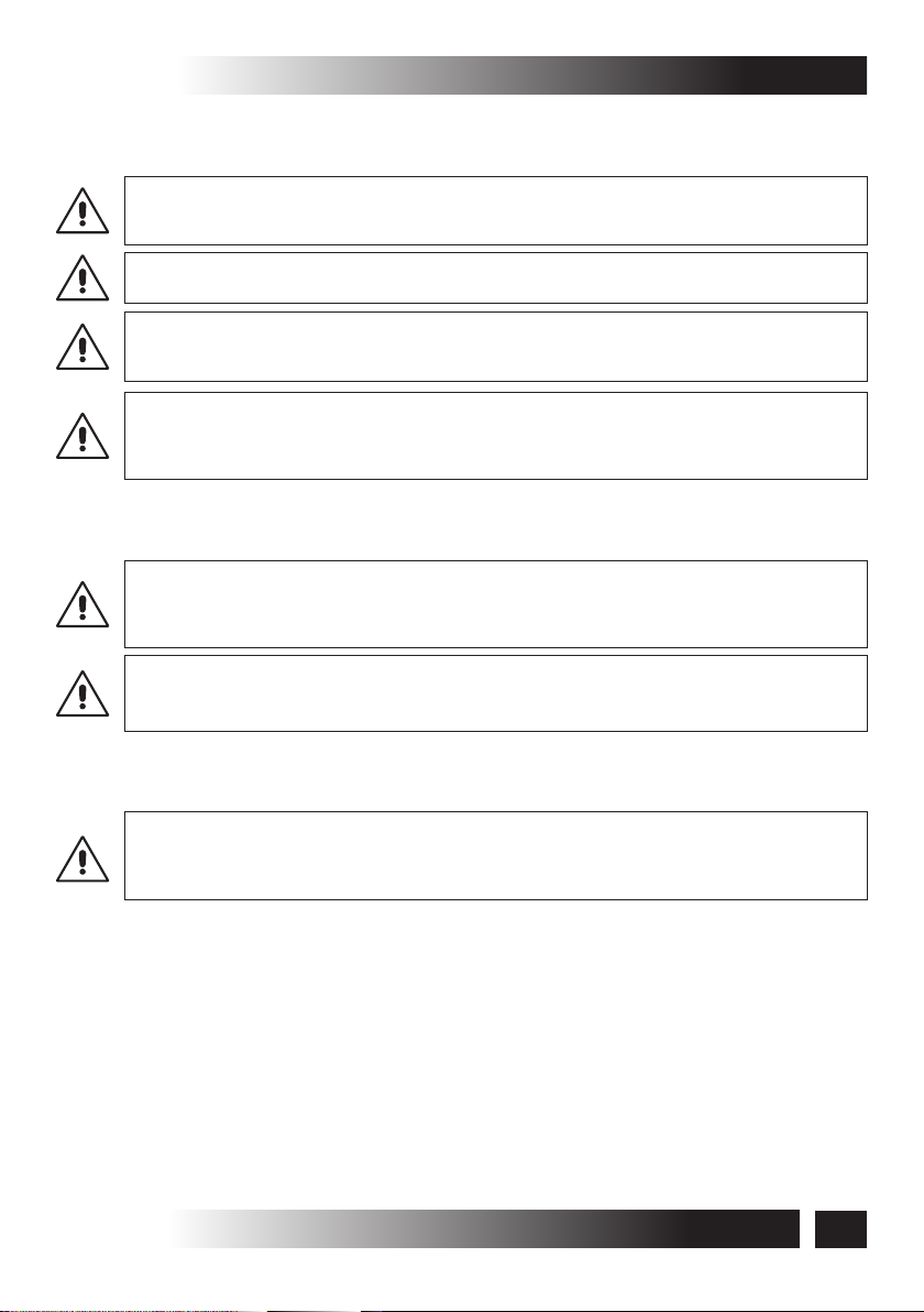
3.2- DENOMINATION OF THE COMPONENTS AND DIMENSIONS
ACK5
Fig. 2
Dimensions in mm
1
2
3
4
5
6
7
8
LEGEND:
1) Power supply cable
2) Support heads
3) Support
4) Opening stroke adjustment on both sides
5) Actuator
6) Chain pin
7) Bracket for bottom hung opening
8) Window frame connection bracket
INSTALLATION AND USE ISTRUCTIONS
8

ACK5
3.3- TECHNICAL DATA
Tab. 1 contains the technical data characterising the actuators.
TECHNICAL DESCRIPTION -3
Power supply voltage
Absorbed current
Absorbed power with load
Thrust force
Tractive force
Idle translation speed
Duration of idle stroke
Minimum window frame height
Adjustable stroke end
(2)
ACK5/230V
230 V - 50 Hz
0,32 A
75 W
27 mm/s
15 s
(1)
Top hung window
Bottom hung window
10 - 15 - 20 - 25 - 30 - 35 - 40 cm
ACK5/24V
24 V
1,35 A
32 W
300 N
300 N
17 mm/s
H = 600 mm
H = 800 mm
Electronics with warning horn to signal to the user the wrong assembling
Protection against electric shocks
Type of service
S
(4)
2
Operating temperature
Protection degree of electric devices
Adjustment of the window frame connection
Class II Class III
2 min
3 min
- 5 ºC + 50 ºC
IP 55
10 mm
23 s
(3)
Parallel electric connection of more
actuators on the same window
Parallel electric connection of more
actuators on different windows
Actuator weight with brackets
Gross weight
(1)
Actuator distance from the window frame opening hinge
(2)
Tolerance on the precision of the output limit switch tripping: +/- 1 cm
(3)
The "buzzer" device is enabled automatically and emits a continuous "beep" as long as the
actuator is fed. For further details on its operation see par. 5.6
(4)
Service of limited duration according to EN 60034
Only with proper
electronic device
Yes
(see wiring diagram)
1,7 kg
1,9 kg
Tab. 1
INSTALLATION AND USE ISTRUCTIONS
9
3- TECHNICAL DESCRIPTION ACK5
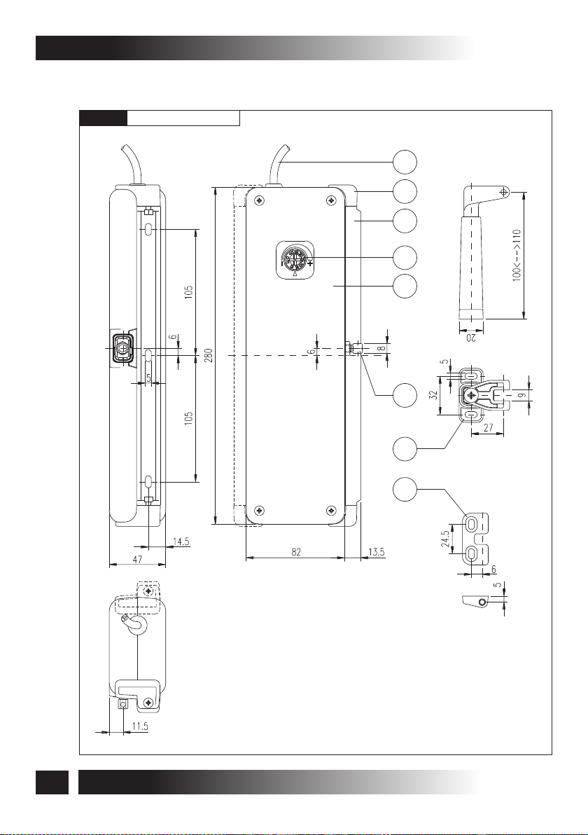
3.4- FORMULAS FOR THE CALCULATION OF THRUST AND TRACTIVE
FORCE
Fig. 3
Horizontal domes or skylights
F = Force necessary for opening or
(N)
closing
P = Weight of the skylight or dome
(N)
F
P
(Only movable part)
F = 0,54 x P
Fig. 4
Top hung windows (A) or
A
bottom hung windows (B)
F = Force necessary for opening or
(N)
closing
P = Weight of the window
(N)
(only movable part)
C = Window opening stroke
(mm)
H = Window height
(mm)
F = (0,54 x P) x ( )
C
H
P
F
C
H
B
C
F
H
P
3.5- DESTINATION OF USE
THE ACTUATOR HAS BEEN DESIGNED AND MANUFACTURED TO PERFORM
AUTOMATICALLY, BY MEANS OF A CONTROL DEVICE, THE OPENING AND CLOSING OF
TOP HUNG WINDOWS, BOTTOM HUNG WINDOWS, PIVOT WINDOWS, AND SKYLIGHTS.
10
INSTALLATION AND USE ISTRUCTIONS
ACK5
TECHNICAL DESCRIPTION -3
3.6- USE LIMITS
The actuator has been designed and manufactured exclusively for the destination of
use given in par .3.5, therefore, any other type of use is strictly forbidden in order to
assure in any moment the safety of the installer and of the user, as well as the
efficiency of the actuator itself.
Check carefully all environmental conditions (temperature, humidity, wind, snow,
potential chemical agents, etc.) and installation settings (misaligned fitting of brackets
and attachment to the frame, frictions produced by hinges or gaskets, use of selfbalancing window stays, etc.) it is recommended that they not exceed the actuator
performances shown in the technical table, Tab1. If they do, please find an alternative
and more suitable product for your application.
IT IS STRICTLY FORBIDDEN TO USE THE ACTUATOR FOR IMPROPER USES OTHER
THAN THE ONE FORESEEN BY THE MANUFACTURER (SEE PAR. 3.5).
IT IS STRICTLY FORBIDDEN TO INSTALL THE ACTUATOR ON THE EXTERNAL SIDE OF
THE WINDOW FRAME SUBJECT TO ATMOSPHERIC AGENTS (RAIN, SNOW, ETC.).
THE USE OF THE ACTUATOR IN ENVIRONMENTS WITH POTENTIALLY EXPLOSIVE
ATMOSPHERE IS STRICTLY FORBIDDEN.
EX
IT IS COMPULSORY TO KEEP THE PACKAGE AND THE ACTUATOR OUT OF REACH OF
CHILDREN.
3.7- PACKAGE
Each standard package of the product (cardboard box) contains (Fig. 5):
• No. 1 Actuator equipped with power supply cable (Ref.A);
Ÿ No. 1 Small parts package (window connection bracket, nuts, pin and fastening
screws for aluminium window frames) (Ref. B);
• No. 1 Adhesive drilling template (Ref. C);
• No. 1 Installation and use instructions (Ref. D);
• No.1 Safety Plate (Fig. 6).
MAKE SURE THAT THE ABOVE DESCRIBED COMPONENTS ARE CONTAINED IN THE
PACKAGE, AS WELL AS THAT THE ACTUATOR HAS NOT BEEN DAMAGED DURING
TRANSPORT.
SHOULD ANY ANOMALY BE DETECTED, IT IS FORBIDDEN TO INSTALL THE ACTUATOR,
AND IT IS COMPULSORY TO REQUIRE TECHNICAL ASSISTANCE FROM YOUR DEALER
OR THE MANUFACTURER.
THE PACKAGING (PAPER, PLASTIC, ETC.) HAS TO BE DISPOSED ACCORDING TO THE
LAWS IN FORCE.
INSTALLATION AND USE ISTRUCTIONS
11

3- TECHNICAL DESCRIPTION ACK5
Fig.5
A
12
B
ORIGINALI
ISTRUZIONI
INSTALLATION
PER
L
’
INST
AND
ALLAZIONE E L'USO
USE
WINDOW
CHAIN
OMAZIONE
ACTUA
A
AUTOMA
CA
FINESTRE
INSTRUCTIONS
TENA
TOR
PER
FOR
TION
ACK
ACK
5
5
A
TTUATORE
AUT
BREVETT
P
ATENTED
A
T
O
PRIMA
DI
INST
BEFORE
L
’
INST
ALLARE
COMPULSORY
ALLAT
ORE
AND
IN
TUTTE
UNDERST
IL
PRESENTE
THIS
MANUALE
MANUAL IS INTEGRAL
PER
AND
OBBLIGATORIAMENTE
FUTURI
MUST
BE PRESERVED FOR
RIFERIMENTI
UNTIL DEMOLITION
COD
P/N 0P
INST
LE
È
P
FINO
. 0P5000
E
UTILIZZARE
ALLING
E L
FOR
’
REV
UTILIZZA
AND
THE
L’
. 05/03
USING
A
REV..
INST
TTUA
SUE
T
AND
ORE
ALLER
THE
T
P
ORE
ARTI
THIS
LEGGANO
ACTUATOR
È
IL
AND
MANUAL IN
OBBLIGA
PRESENTE
THE
E
COMPRENDANO
, IT
USER
T
ORIO
IS
ALL ITS
ARTE
MANUALE
TO
CHE
INTEGRANTE
READ
P
ARTS.
.
P
ART
ESSERE
OF THE
DELL
ALLA
FUTURE
’
A
CONSERV
ACTUA
TTUA
DEMOLIZIONE
OF
THE
TORE
REFERENCE
TOR
A
SAME
TO
E
DEVE
DELLO
.
STESSO
.
INSTALLATION AND USE ISTRUCTIONS
C
D

SAFETY -4ACK5
4.1- GENERAL INSTRUCTIONS
OPERATORS MUST BE INFORMED OF ACCIDENT RISKS, SAFETY DEVICES AND THE
GENERAL ACCIDENT PREVENTION REGULATIONS ESTABLISHED BY INTERNATIONAL
DIRECTIVES AND BY THE LAW IN FORCE IN THE COUNTRY OF USE.
ALL OPERATORS MUST STRICTLY COMPLY WITH THE ACCIDENT PREVENTION
REGULATIONS IN FORCE IN THE COUNTRY OF USE.
DO NOT REMOVE OR ALTER THE PLATES PLACED ON THE ACTUATOR BY THE
MANUFACTURER.
IF THE WINDOW FRAME IS ACCESSIBLE FROM OR INSTALLED AT A HEIGHT OF LESS
THAN 2.5 m FROM THE GROUND, AND IF IT CAN BE COMMANDED BY AN UNTRAINED
USER OR WITH A REMOTE CONTROL DEVICE, FIT AN EMERGENCY STOP SYSTEM
WHICH AUTOMATICALLY CUTS IN TO PREVENT THE RISK OF CRUSHING OR
DRAGGING PARTS OF THE BODY INSERTED BETWEEN THE MOVING AND FIXED PARTS
OF THE WINDOW FRAME.
ANY TAMPERING WITH OR UNAUTHORISED REPLACEMENT OF ONE OR MORE PARTS
OR COMPONENTS OF THE ACTUATOR, OR THE USE OF UNORIGINAL ACCESSORIES
AND CONSUMABLES, MAY INCREASE THE RISK OF ACCIDENT AND THUS RELIEVES
THE MANUFACTURER OF ALL CIVIL AND PENAL LIABILITY
EXTRAORDINARY AND ROUTINE MAINTENANCE OPERATIONS INVOLVING THE TOTAL
OR PARTIAL DISMOUNTING OF THE ACTUATOR MAY ONLY BE PERFORMED AFTER
DISCONNECTING IT FROM THE POWER SUPPLY.
THIS APPLIANCE MAY NOT BE USED BY PERSONS (CHILDREN INCLUDED) WITH
REDUCED PHYSICAL, SENSORIAL OR MENTAL CAPACITIES, OR INEXPERT PEOPLE,
UNLESS THEY ARE SUPERVISED AND TAUGHT HOW TO USE IT BY A PERSON
RESPONSIBLE FOR THEIR SAFETY. CHILDREN MUST BE CONTROLLED TO MAKE
SURE THEY DO NOT PLAY WITH THE APPLIANCE.
4.2- SAFETY DEVICES
4.2.1- PROTECTION AGAINST ELECTRIC HAZARD
The actuator is protected against electric hazard due to direct and indirect contacts.
The protection measures against direct contacts aim at protecting people against
hazards due to contact with active parts, usually live parts; while the protection
measures against indirect contacts aim at protecting people against hazards due to
conducing part, which are usually insulated, but could become live in case of failure
(insulation failure).
The adopted protection measures are the following:
1) Insulation of live parts by means of a plastic material body;
2) Enclosure with suitable protection degree;
INSTALLATION AND USE ISTRUCTIONS
13

4- SAFETY ACK5
3) Only for the mod. ACK5/230V provided with protection against electric shocks:
Protection of passive type given by the use of components with double insulation,
also called components of class II or with equivalent insulation.
4.3- SAFETY PLATES
IT IS FORBIDDEN TO REMOVE, MOVE, SPOIL OR IN ANYWAY REDUCE THE VISIBILITY
OF THE SAFETY PLATES. FAILURE TO OBSERVE THE ABOVE MAY CAUSE SERIOUS
HARM TO PEOPLE AND DAMAGE TO PROPERTY. THE MANUFACTURER DECLINES ALL
LIABILITY FOR ANY DAMAGE CAUSED BY THE FAILURE TO OBSERVE THE ABOVE
REQUIREMENT.
Fig. 6 illustrates the safety plate: this must applied directly to the outside of the actuator
or near it and always in a position where it can be seen by the installer and/or operator.
4.4- RESIDUAL RISKS
The installer and the user are herewith informed that after the actuator has been
installed on the window, the actuator drive can accidentally generate the following
residual risk:
Residual risk:Hazard of squashing or dragging of body parts inserted between the
movable and the fix part of the window frame.
Exposure frequency: Accidental and when the installer or the user decides to perform
a wrong voluntary action.
Severity of the damage:Light lesions (usually reversible).
Adopted measures:Before enabling the device, it is compulsory to verify that near the
window there are not persons, animals or things whose safety may be accidentally
jeopardized. During actuator operation, it is compulsory to be in a safe control position
assuring visual control on the window movement (see par. 6.1).
14
Fig. 6
MACCHINA AD AVVIAMENTO AUTOMATICO
AUTOMATIC MACHINE
PRIMA DI INSTALLARE E UTILIZZARE L'ATTUATORE È OBBLIGATORIO CHE L'INSTALLATORE E L'UTILIZZATORE
LEGGANO E COMPRENDANO IN TUTTE LE SUE PARTI IL MANUALE
THE INSTALLER AND USER MUST READ AND UNDERSTAND ALL PARTS OF THIS MANUAL BEFORE INSTALLING
AND USING THE ACTUATOR.
PERICOLO ATTENZIONE ALLE MANI
BEWARE OF YOUR HANDS
ATTENZIONE MACCHINA AD AVVIAMENTO AUTOMATICO CON COMANDO A DISTANZA
ATTENTION! AUTOMATIC MACHINE WITH REMOTE CONTROL DEVICE
INSTALLATION AND USE ISTRUCTIONS
IT
EN

ACK5
INSTALLATION -5
5.1- GENERAL INSTRUCTIONS
THE ACTUATOR INSTALLATION CAN BE PERFORMED EXCLUSIVELY BY COMPETENT
AND QUALIFIED TECHNICAL PERSONNEL SATISFYING THE PROFESSIONAL AND
TECHNICAL REQUIREMENTS FORESEEN BY THE LAWS IN FORCE IN THE COUNTRY OF
INSTALLATION.
THE ACTUATOR PERFORMANCE MUST BE SUFFICIENT TO ASSURE THE CORRECT
MOVEMENT OF THE WINDOW. IT IS COMPULSORY TO VERIFY THE THRUST OR
TRACTIVE FORCE ACCORDING TO THE TYPE AND WEIGHT OF THE WINDOW (PAR. 3.4).
IT IS FORBIDDEN TO EXCEED THE LIMITS GIVEN IN TAB. 1 CONCERNING THE
TECHNICAL DATA (PAR. 3.3).
THE ACTUATOR INSTALLATION MUST BE PERFORMED EXCLUSIVELY WITH CLOSED
WINDOW OR SKYLIGHT.
BEFORE PERFORMING THE INSTALLATION OF THE ACTUATOR ON HOPPER
WINDOWS, VERIFY THAT ON BOTH SIDES OF THE WINDOW TWO COMPASS STROKE
LIMIT DEVICES ARE INSTALLED IN ORDER TO AVOID THE ACCIDENTAL FALL OF THE
WINDOW.
FOR CORRECT OPERATION OF THE ACTUATOR, THE WINDOW MUST HAVE A MINIMUM
HEIGHT OF 800 mm (DISTANCE OF THE ACTUATOR FROM THE WINDOW OPENING
HINGE). OTHERWISE, ASK YOUR DEALER OR THE MANUFACTURER FOR THE
NECESSARY ACCESSORIES FOR A CORRECT INSTALLATION.
VERIFY THAT THE DISTANCE "D" BETWEEN THE FIXED PART OF THE WINDOW (ON
WHICH THE FIXING OF THE ACTUATOR IS FORESEEN - FIG. 7 - REF. 1) AND THE
MOVABLE PART OF THE WINDOW (ON WHICH THE BRACKET FIXING IS FORESEEN FIG. 7 - REF. 2) IS INCLUDED WITHIN 0 AND 10 mm. OTHERWISE, ASK YOUR DEALER OR
THE MANUFACTURER FOR THE NECESSARY ACCESSORIES FOR A CORRECT
INSTALLATION (SEE CHAP. 9)
Fig. 7
D= 0 10 mm÷
2
1
INSTALLATION AND USE ISTRUCTIONS
15

5- IINSTALLATION
ACK5
5.2- TOP HUNG WINDOWS
Fig. 8
(Fig. 8 and 16÷26)
1) Open the package (par. 3.7) and extract the
various components;
2) Fig. 17- With a pencil draw the centre line "X" of
the window frame;
3) Fig. 18- Select the following components:
bracket "S1", support "SA", two nuts "D1", two
screws "V1", heads "T1" and “T2";
4) Fig. 19- Insert the two nuts "D1" on the support
"SA" and mount the head "T1" by fixing it using
screw "V1";
5) Fig. 20- Cut out the adhesive template "DS" and apply it on the window frame
centring it on the previously drawn centre line "X";
CAUTION: FOR NON-COPLANAR WINDOW FRAMES, IT IS NECESSARY TO CUT THE
TEMPLATE CONCERNED PART AND TO APPLY IT ON THE WINDOW FRAME PAYING
ATTENTION TO KEEP IT IN THE SAME REFERENCE POSITION.
6) With a suitable drill, create on the window frame holes having the related diameter,
given on the adhesive template "DS";
7) Fig. 21- Mount the support "SA" on the fix window frame with the screws "V2"; Check
the perfect horizontal and vertical alignment with the window frame;
8) Fig. 22- Mount the bracket "S1" on the movable window frame with the screws "V2";
9) Mount the actuator on the support "SA", place the head "T2" and tighten the screw "V1;
VERIFY THAT THE CHAIN END "TC" IS ON THE SAME AXIS OF THE BRACKET "S1".
OTHERWISE, LOOSEN THE FIXING SCREWS AND POSITION IT CORRECTLY. WHEN THE
DEVICES ARE NOT COAXIAL, THIS MAY DAMAGE THE ACTUATOR AND THE WINDOW
FRAME (FIG. 9).
Fig. 9
YES
16
NO
TC TC
INSTALLATION AND USE ISTRUCTIONS
S1 S1

ACK5
INSTALLATION -5
10) Fig. 23- Mount the nut "D2" on the screw "V3" and then it on the chain ending "TC";
Fig. 24- Connect the bracket "S1" to the screw "V3" by means of the pin "P";
11) Perform the electric connections according to the prescriptions of par. 5.4, as well
as with reference to the wiring diagram;
12) Fig. 25- Act with a screwdriver or with a coin on the adjustment screw "VR", setting
the wished opening stroke (cm);
CAUTION: VERIFY THAT THE SELECTED STROKE IS SOME CENTIMETRES LOWER
THAN THE STROKE EFFECTIVELY ALLOWED BY MECHANICAL LOCKS, COMPASS
STROKE LIMIT DEVICES, OR WING OPENING HINDRANCES.
13) Fig. 26- Perform a test of complete window frame opening and closing. After the
closing phase, verify that the chain end "TC" is completely returned in its seat
(Ref. A);
14) If the closing is right (Ref. A), fix the screw "V3" with the nut "D2" and the pin "P".
If the closing is not precise (Ref. B), perform the necessary adjustment of the screw
"V3" and of the nut "D2".
FOR A CORRECT ADJUSTMENT OF THE WINDOW FRAME CLOSING SEE THE
INDICATIONS GIVEN IN PAR. 5.6.
5.3- BOTTOM HUNG WINDOWS
Fig. 10
(Fig. 10 and 27÷37)
1) Open the package (par. 3.7) and extract the
various components;
2) Fig. 28- With a pencil draw the centre line "Y" of
the window frame;
3) Fig. 29- Select the following components:
bracket "S2" and "S3", support "SA", two nuts
"D1", two screws "V1", screw "V4", heads "T1"
and "T2";
4) Fig. 30- Insert the two nuts "D1" on the support
"SA" and mount the head "T2" by fixing it using screw "V1";
5) Fig. 31- Cut out the adhesive template "DV" and apply it on the window frame
centring it on the previously drawn centre line "Y";
CAUTION: FOR NON-COPLANAR WINDOW FRAMES, IT IS NECESSARY TO CUT THE
TEMPLATE CONCERNED PART AND TO APPLY IT ON THE WINDOW FRAME PAYING
ATTENTION TO KEEP IT IN THE SAME REFERENCE POSITION.
INSTALLATION AND USE ISTRUCTIONS
17

5- INSTALLATION
6) With a suitable drill, create on the window frame holes given on the adhesive
template "DV";
7) Fig. 32- Mount the support "SA" on the fix window frame with the screws "V2"; check
the perfect horizontal and vertical alignment with the window frame;
8) Fig. 33- Mount the bracket "S2" on the movable window frame with the screws "V2";
9) Mount the actuator on the support "SA", place the head "T1" and tighten the screw
"V1;
VERIFY THAT THE CHAIN END "TC" IS ON THE SAME AXIS OF THE BRACKET "S1".
OTHERWISE, LOOSEN THE FIXING SCREWS AND POSITION IT CORRECTLY. WHEN THE
DEVICES ARE NOT COAXIAL, THIS MAY DAMAGE THE ACTUATOR AND THE WINDOW
FRAME (SEE FIG. 9).
10) Fig.34- Mount the nut "D2" on the screw "V3" and then it on the chain end "TC";
Fig.35- Connect the bracket "S3" to bracket "S2" and fix it with the screw "V4".
Connect the bracket "S3" with the screw "V3" by means of the pin "P";
11) Perform the electric connections according to the prescriptions of par. 5.4, as well
as with reference to the wiring diagram;
12) Fig. 36- Act with a screwdriver or with a coin on the adjustment screw "VR", setting
the wished opening stroke (cm);
CAUTION: VERIFY THAT THE SELECTED STROKE IS SOME CENTIMETRES LOWER
THAN THE STROKE EFFECTIVELY ALLOWED BY MECHANICAL LOCKS, COMPASS
STROKE LIMIT DEVICES, OR WING OPENING HINDRANCES.
ACK5
13) Fig. 37- Perform a test of complete window frame opening and closing. After the
closing phase, verify that the chain end "TC" is completely returned in its seat
(Ref. A);
14) If the closing is right (Ref. A), fix the screw "V3" with the nut "D2" and the pin "P".
If the closing is not precise (Ref. B), perform the necessary adjustment of the screw
"V3" and of the nut "D2". If necessary, act also on the bracket "S3", unscrewing the
screw "V4" it is possible to unhook the two brackets modifying their coupling
position.
FOR A CORRECT ADJUSTMENT OF THE WINDOW FRAME CLOSING SEE THE
INDICATIONS GIVEN IN PAR. 5.6.
18
INSTALLATION AND USE ISTRUCTIONS

ACK5
INSTALLATION -5
5.4- ELECTRIC CONNECTIONS (Wiring diagram)
THE ELECTRIC CONNECTION OF THE ACTUATOR CAN BE PERFORMED ONLY BY
COMPETENT AND QUALIFIED TECHNICAL PERSONNEL SATISFYING THE TECHNICAL
AND PROFESSIONAL REQUIREMENTS FORESEEN BY THE LAW IN FORCE IN THE
COUNTRY OF INSTALLATION ISSUING TO THE CUSTOMER A DECLARATION OF
CONFORMITY FOR THE CONNECTION AND/OR THE PLANT PERFORMED.
THE ELECTRIC CONNECTION OF THE VERSION ACK5/24V HAS TO BE CARRIED OUT
WITH A VERY LOW SAFETY VOLTAGE FEEDER PROTECTED AGAINST SHORT
CIRCUITS.
BEFORE PERFORMING THE ELECTRIC CONNECTION OF THE ACTUATOR, VERIFY THE
CORRECT INSTALLATION ON THE WINDOW.
THE MAINS TO WHICH THE ACTUATOR IS CONNECTED MUST COMPLY WITH THE
REQUIREMENTS OF THE LAWS IN FORCE IN THE COUNTRY OF INSTALLATION, AS
WELL AS SATISFY THE TECHNICAL FEATURES GIVEN IN TAB. 1 AND ON THE RATING
PLATE AND THE "CE" MARKING (PAR. 3.1).
THE SECTION OF THE MAINS CABLES MUST BE PROPERLY SIZED ACCORDING TO THE
ABSORBED ELECTRIC POWER (SEE RATING PLATE AND "CE" MARKING).
ANY TYPE OF ELECTRIC MATERIAL (PLUG, CABLE, TERMINALS, ETC.) USED FOR THE
CONNECTION MUST BE SUITABLE FOR THE USE, WITH "CE" MARKING AND
COMPLYING WITH THE REQUIREMENTS FORESEEN BY THE LAWS IN FORCE IN THE
COUNTRY OF INSTALLATION.
TO ASSURE EFFICIENT SEPARATION FROM THE MAINS, INSTALL AN APPROVED
TEMPORARY BIPOLAR SWITCH (PUSH-BUTTON) UPLINE OF THE DEVICE. FIT A
BIPOLAR MAIN SWITCH WITH CONTACT APERTURE OF AT LEAST 3 mm UP LONE OF
THE CONTROL LINE.
BEFORE PERFORMING THE ELECTRIC CONNECTION OF THE ACTUATOR, VERIFY
THAT THE POWER SUPPLY CABLE IS NOT DAMAGED. SHOULD IT BE DAMAGED, IT
MUST BE REPLACED BY THE MANUFACTURER OR BY THE TECHNICAL ASSISTANCE
SERVICE OR IN ANY CASE BY AUTHORIZED OPERATORS.
5.5- CONTROL DEVICES
THE CONTROL DEVICES USED TO DRIVE THE ACTUATOR MUST ASSURE THE SAFETY
CONDITIONS FORESEEN BY THE LAWS IN FORCE IN THE COUNTRY OF USE.
According to the different type of installations, the actuators can be driven by the
following control devices:
1) MANUAL PUSH-BUTTON:
Bipolar switch button with central OFF position, with biased-off switch;
INSTALLATION AND USE ISTRUCTIONS
19

5- INSTALLATION
2) CONTROL AND FEEDING UNIT:
Microprocessor control units controlling the single actuator or (e.g.: Mod. TF, etc.)
more than one actuator simultaneously by means of one or more manual pushbuttons, an infrared remote control or a 433 Mhz radio control.
To these control units, it is possible to connect the rain sensors (RDC - 12V), the wind
sensor (RW) and the brightness sensor;
THE EVENTUALLY USED UNITS MUST SUPPLY A VOLTAGE TO ACK5 FOR MAX. 120 s.
3) SYNCHRONIZATION UNIT:
Microprocessor control unit (USA2) controlling by means of a manual push-button
the simultaneous operation of 2 actuators installed on a single window assuring the
regular opening and closing movement.
5.6- ADJUSTMENT OF THE WINDOW FRAME CLOSING (Fig. 25-35)
THE CORRECT ADJUSTMENT OF THE WINDOW FRAME CLOSING ASSURES THE LIFE
AND THE TIGHTNESS OF THE SEALS, AS WELL AS THE GOOD OPERATION OF THE
ACTUATOR.
A good method to perform the adjustment is to let the chain go back without load into the
actuator and, then, to measure the position of the chain ending with reference to the
external casings.
Then, tighten the window frame fixing screw and let the chain go back.
The adjustment is right, when with closed window the chain ending has the same
position detected during the test without load.
ACK5
As given in Fig. 26 - Ref. B (top hung windows) and in Fig. 37 - Ref. B (bottom hung
windows), although the window is closed, part of the chain ending or of the chain itself
has not come back completely into the actuator casings causing the failed tripping of the
related limit switch related to the chain re-entering. In this case, the actuator motor
remains under conditions of maximum stress, until the electronic protection trips and
the "BUZZER" is enabled.
This warning horn emits a continuous "beep" as long as the actuator is
connected to the power supply.
CONSIDERING THAT THIS ADDITIONAL SAFETY DEVICE HAS BEEN DEVELOPED IN
ORDER TO OFFER A RAPID SYSTEM TO DETECT ANY EVENTUAL ANOMALY IN THE
ASSEMBLY OF THE DEVICE, FOR A CORRECT INSTALLATION OF THE PRODUCT IT IS
COMPULSORY TO FOLLOW ALL THE ASSEMBLING PROCEDURES DESCRIBED IN THIS
MANUAL.
20
INSTALLATION AND USE ISTRUCTIONS

ACK5
INSTALLATION -5
5.7- EMERGENCY PROCEDURES
Should it be necessary to open the window manually due to power supply failure or
mechanism block, follow these instructions:
BEFORE PERFORMING ANY TYPE OF INTERVENTION ON THE ACTUATOR AND ON THE
WINDOW, IT IS COMPULSORY TO DISCONNECT THE POWER SUPPLY OF THE
ACTUATOR AND TO PUT ON "0" THE EVENTUAL SWITCHES OF THE CONTROL
DEVICES.
IT IS COMPULSORY TO PADLOCK THE MAIN SWITCH OF THE DISCONNECTION DEVICE
INSTALLED ON THE MAINS IN ORDER TO AVOID ANY UNEXPECTED START. IF THE MAIN
SWITCH CANNOT BE PADLOCKED, IT IS COMPULSORY TO PLACE A SIGN FORBIDDING
THE ENABLING.
IN SOME CASES, THE EVENT OF POSSIBLE ANOMALIES MIGHT STALL ALSO OTHER
ACTUATORS CONNECTED IN PARALLEL. TO FIND THE SUPPOSED MALFUNCTIONING
ACTUATOR, RUN SOME CLOSING OPERATIONS IN SUCCESSION (ABOUT 10
OPERATIONS EVERY 2 SECONDS), TILL THE WORKING ACTUATORS START RUNNING
AGAIN.
1) Act on the pin "P" until it is completely extracted from the bracket "S1" (top hung
windows - Fig. 11). Act on the pin "P" until it is completely extracted from the bracket
"S3" (bottom hung windows - Fig. 12);
2) Open the window manually.
Fig. 11
S1
P
Fig. 12
S3
INSTALLATION AND USE ISTRUCTIONS
P
21

6- USE AND OPERATION
6.1- USE OF THE ACTUATOR
THE ACTUATOR CAN BE USED ONLY BY A USER ACTING IN COMPLIANCE WITH THE
INSTRUCTIONS GIVEN IN THIS MANUAL AND/OR IN THE MANUAL OF THE ACTUATOR
COMMAND DEVICE (e.g.: WIND AND RAIN CONTROL UNIT).
BEFORE USING THE ACTUATOR, IT IS COMPULSORY FOR THE USER TO READ AND
UNDERSTAND IN ALL ITS PARTS THIS MANUAL, AS WELL AS THE EVENTUAL MANUAL
OF THE INSTALLED CONTROL DEVICE TYPE.
BEFORE OPERATING THE ACTUATOR, THE USER MUST COMPULSORILY VERIFY THAT
NEAR AND/OR UNDER THE WINDOW THERE ARE NOT ANY PERSON, ANIMAL AND
THING WHOSE SAFETY MAY BE ACCIDENTALLY JEOPARDISED (SEE PAR. 4.4).
DURING THE OPERATION OF THE ACTUATOR CONTROL DEVICE, THE USER HAS TO
COMPULSORILY OCCUPY A CONTROL POSITION ASSURING VISUAL CONTROL ON
THE WINDOW MOVEMENT.
THE FUNCTION EFFICIENCY AND THE RATED PERFORMANCE OF THE ACTUATOR, OF
THE WINDOW FRAME ON WHICH IT IS INSTALLED AND OF THE ELECTRIC EQUIPMENT
MUST BE VERIFIED STEADILY IN TIME BY PERFORMING, WHEN NECESSARY,
INTERVENTIONS OF ROUTINE AND SUPPLEMENTARY MAINTENANCE ASSURING THE
OPERATION CONDITIONS IN COMPLIANCE WITH THE SAFETY REGULATIONS.
ALL ABOVE MENTIONED MAINTENANCE INTERVENTIONS MAY BE PERFORMED
EXCLUSIVELY BY TECHNICAL COMPETENT AND QUALIFIED TECHNICAL PERSONNEL
SATISFYING THE TECHNICAL AND PROFESSIONAL REQUIREMENTS FORESEEN BY
THE LAW IN FORCE IN THE COUNTRY OF INSTALLATION.
ACK5
The use of the actuator allows to control automatically the opening and closing of the
window according to the type of control device installed (see par. 5.5).
22
INSTALLATION AND USE ISTRUCTIONS

ACK5
MAINTENANCE -7
7.1- GENERAL INSTRUCTIONS
IF THE ACTUATOR WORKS INCORRECTLY, CONTACT THE MANUFACTURER.
ANY WORK ON THE ACTUATOR (E.G.: POWER CABLE, ETC.) OR ITS COMPONENTS MAY
ONLY BE CARRIED OUT BY PERSONNEL QUALIFIED BY THE MANUFACTURER.
TOPP DECLINES ALL LIABILITY FOR WORK PERFORMED BY UNAUTHORISED PEOPLE.
The actuator incorporates components that do not require significant routine or
extraordinary maintenance operations.
The recommended maintenance activities should in any case involve the periodical
execution of at least the following operations: that the actuator assembly components
are clean, the replacement of components that show signs of superficial damage such
as injuries, cracks, discoloration, etc., the fixing systems (brackets and screws) are
tight, the window frame is not deformed and the seals are tight, and check the cables
and connectors.
This maintenance activity may be carried out either by TOPP, in accordance with a
specific agreement made with the user, or by the installation technician or by other
competent and qualified technical personnel in possession of all legal requirements.
INSTALLATION AND USE ISTRUCTIONS
23

8- DEMOLITION
8.1- GENERAL INSTRUCTIONS
THE DEMOLITION OF THE ACTUATOR MUST OCCUR IN COMPLIANCE WITH THE LAWS
IN FORCE ON ENVIRONMENT PROTECTION.
DIFFERENTIATE THE PARTS MAKING UP THE ACTUATOR ACCORDING TO THEIR
DIFFERENT MATERIAL TYPE (PLASTIC, ALUMINIUM, ETC.).
ACK5
9- SPARE PARTS AND ACCESSORIES UPON REQUEST
9.1- GENERAL INSTRUCTIONS
THE USE OF "NON-ORIGINAL" SPARE PARTS AND ACCESSORIES WHICH MAY
ENDANGER THE SAFETY AND THE EFFICIENCY OF THE ACTUATOR IS FORBIDDEN.
THIS ACTION SHALL INVOLVE THE WARRANTY EXPIRATION.
ORIGINAL SPARE PARTS AND ACCESSORIES HAVE TO BE REQUESTED EXCLUSIVELY
TO YOUR DEALER OR TO THE MANUFACTURER STATING TYPE, MODEL, SERIAL
NUMBER, AND YEAR OF CONSTRUCTION OF THE ACTUATOR.
24
INSTALLATION AND USE ISTRUCTIONS
ACK5

ACK5
SPARE PARTS AND ACCESSORIES UPON REQUEST -9
Fig. 13
FRAME ADJUSTMENT PINS
0
÷ 1
D= 0
30
÷
D= 20
COD
. 0B0008
(Standard)
COD
. 0B0007
20
÷
D= 10
40
÷
D= 30
COD
COD
. 0B0005
. 0B0006
INSTALLATION AND USE ISTRUCTIONS
25

9- SPARE PARTS AND ACCESSORIES UPON REQUEST
Fig. 14
VERTICAL MOUNTING BRACKET (COD. 3A1380-81-82)
(D)
ACK5
FOR A CORRECT OPERATION, THE WINDOW MUST HAVE A MIN.
HEIGHT OF 800 mm (ACTUATOR DISTANCE FROM THE WINDOW
FRAME OPENING HINGE).
SINGLE SWIVEL BRACKET (COD. 1A1665-66-67)
(D)
50
FRAME
21.5
35
1.7
2
WING
22.3
2.8
50
47.8
85
106.5±4
FRAME
54.4
45.5
(A)
WING
58.5
(A)
Overlapped part
(D)
0 ÷ 10 mm
10 ÷ 20 mm
20 ÷ 30 mm
30 ÷ 40 mm
23.5
11.8
27
15.2
Window frame
adjustment
pin code
0B0008
(Standard)
0B0005
0B0007
0B0006
THE FIXING POSITION (A) HAS TO BE VERIFIED AND EVALUATED ACCORDING TO THE PROFILE/WIDTH OF THE
WING/FRAME AND OF THE WINDOW LIGHT. THE ACTUATOR WITH SWIVEL BRACKET CAN BE SUBJECT TO A MAX.
THRUST FORCE NOT EXCEEDING 250 N FOR A CORRECT OPERATION, THE WINDOW MUST HAVE A MIN. HEIGHT OF
400 mm (ACTUATOR DISTANCE FROM THE WINDOW FRAME OPENING HINGE).
26
INSTALLATION AND USE ISTRUCTIONS

ACK5
Fig. 15
SPARE PARTS AND ACCESSORIES UPON REQUEST -9
SMALL SWIVEL BRACKET (COD. 3A1396-97-98-99)
WING
(D)
Make sure that the M6
nut is tightly fastened
M6 nut
(A)
FRAME
(D)
Window frame
adjustment
pin code
0B0008
(Standard)
0B0005
0B0007
0B0006
Overlapped part
BIG SWIVEL BRACKET (COD.3A1391-92-93-94)
(D)
WING
M6 nut
FRAME
THE FIXING POSITION (A) HAS TO BE VERIFIED AND EVALUATED ACCORDING TO THE PROFILE/WIDTH OF THE
WING/FRAME AND OF THE WINDOW LIGHT. THE ACTUATOR WITH SWIVEL BRACKET CAN BE SUBJECT TO A MAX.
THRUST FORCE NOT EXCEEDING 250 N FOR A CORRECT OPERATION, THE WINDOW MUST HAVE A MIN. HEIGHT OF
400 mm (ACTUATOR DISTANCE FROM THE WINDOW FRAME OPENING HINGE).
THE CHAIN CAN CURVE BOTH UPWARDS AND DOWNWARDS DEPENDING ON THE WINDOW'S WEIGHT, ON THE
DISTANCE BETWEEN THE PUSH POINT AND THE HINGES, ON THE WIND. THIS DOES NOT AFFECT THE GOOD
PERFORMANCES OF THE ACTUATOR.
Make sure that the M6
nut is tightly fastened
0 ÷ 10 mm
10 ÷ 20 mm
20 ÷ 30 mm
30 ÷ 40 mm
INSTALLATION AND USE ISTRUCTIONS
27

INSTALLATION ON TOP HUNG WINDOWS
Fig. 16
D
0÷10mm (Standard)
ACK5
31
12
10
Wing
Frame
27.5
Overlapped part
D
0 ÷ 10 mm
10 ÷ 20 mm
20 ÷ 30 mm
30 ÷ 40 mm
45.5
47.8
55.2
96.7
Window frame
adjustment
pin code
0B0008
(Standard)
0B0005
0B0007
0B0006
28
INSTALLATION AND USE ISTRUCTIONS

ACK5
Fig. 17 Fig. 18
INSTALLATION ON TOP HUNG WINDOWS
X
T1 T2 S1SA
Fig. 19
D1
T1V1
Fig. 20 Fig. 21
DS
X
SA
SA
D1
V1
D1
INSTALLATION AND USE ISTRUCTIONS
V2
29

INSTALLATION ON TOP HUNG WINDOWS
ACK5
Fig. 22
Fig. 24
Fig. 23
S1SA
T2 V1
TC
V3
D2
Fig. 25
S1
P
VR
Fig. 26
30
(A)
TC
(B)
P D2V3
INSTALLATION AND USE ISTRUCTIONS

ACK5
INSTALLATION ON BOTTOM HUNG WINDOWS
Fig. 27
36.5
12.5
APPLICATION 2
T1 and T2 head upwards
D
0÷5mm
Frame
Wing
27.5
2.5
55.2
18
96.3
C
105÷110
Frame
D
0÷5mm
APPLICATION 1
T1 and T2 head downwards
47.8
27
96.3
55.2
27.5
47.8
27
12.5
Wing
C
105÷110
VERIFY THAT THE DISTANCE "D" BETWEEN THE FIXED PART AND THE MOVABLE PART
OF THE WINDOW IS INCLUDED WITHIN 0 AND 5 mm.
THE DISTANCE “C” IS ADJUSTABLE FROM 105 TO 110 MM DEPENDING ON THE
OVERLAP “D”.
INSTALLATION AND USE ISTRUCTIONS
31

INSTALLATION ON BOTTOM HUNG WINDOWS
Fig. 28 Fig. 29
ACK5
Fig. 30
T1
SA
T2
Y
D1
V1
SA
D1
T2V1
V4
D1
S3S2
Fig. 31 Fig. 32
DV
SA
Y
32
INSTALLATION AND USE ISTRUCTIONS
V2

ACK5
Fig. 33 Fig. 34
INSTALLATION ON BOTTOM HUNG WINDOWS
T1
TC
V1
SA
S2
Fig. 35 Fig. 36
V3
P
S2 S3 V4
Fig. 37
V3
D2
D2
VR
V3
(A)
TC
(B)
P
INSTALLATION AND USE ISTRUCTIONS
33

DRAWINGS FOR INSTALLATION
Wiring diagram
L
N
ACK5
L
N
230 V24 V
CLOSES
230V~50Hz
ACK5
A AA A
ACK5
24V
CLOSES
BROWN
GREY
BLACK
OPENS
THIS SYMBOL IDENTIFIES THE TOPP ELECTRICAL ACTUATOR
IN WIRING DIAGRAMS.
A
(LIGHT BLUE)
OPENS
CLOSES
230V~50Hz
ACK5
CLOSES
24V
BROWN
A
GREY
BLACK
OPENS
(LIGHT BLUE)
OPENS
34
ACK5
THIS SYMBOL IDENTIFIES THE TOPP ELECTRICAL ACTUATOR
IN WIRING DIAGRAMS.
ACK5
BLUE
(BLACK)
(RED)
BROWN
A
INSTALLATION AND USE ISTRUCTIONS
BLUE
(BLACK)
A
ACK5
(RED)
BROWN


TOPP S.r.l.
Società a Socio Unico soggetta a direzione e coordinamento di 2 Plus 3 Holding S.p.a.
Via Galvani, 59 - 36066 Sandrigo (VI) - Italia
Tel. +39 0444 656700 - Fax +39 0444 656701
Info@topp.it - www.topp.it
 Loading...