

TOPP ACK4, ACK42, ACK44 Installation And Use Instructions Manual
PATENTED
BEFORE INSTALLING AND USING THE ACTUATOR, IT IS
COMPULSORY FOR THE INSTALLER AND THE USER TO READ
AND UNDERSTAND THIS MANUAL IN ALL ITS PARTS.
THIS MANUAL IS INTEGRAL PART OF THE ACTUATOR
AND MUST BE PRESERVED FOR FUTURE REFERENCE
UNTIL DEMOLITION OF THE SAME.
ACK4
INSTALLATION AND USE INSTRUCTIONS
CHAIN ACTUATOR FOR
WINDOW AUTOMATION
P/N 0P5101
VER.0.0 REV.11.12


3
1- DECLARATION OF "CE" CONFORMITY
2- GENERAL REMARKS
2.1- General instructions ..........................................................................................
2.2- Installer and user
2.3- Warranty
2.4- Technical assistance
2.5- Reserved rights
3- TECHNICAL DESCRIPTION
3.1- Rating plate and "CE" marking
3.2- Denomination of the components and dimensions............................................page 08
3.3- Technical data ...................................................................................................page 09
3.4- Formulas for the calculation of thrust force or tractive force.............................page 10
3.5- Destination of use .............................................................................................page 10
3.6- Use Limits..........................................................................................................page 11
3.7- Package.............................................................................................................page 11
4- SAFETY
4.1- General instructions ..........................................................................................page 13
4.2- Safety devices...................................................................................................page 13
4.2.1- Protections against electric hazard...........................................................page 13
4.3- Safety plates......................................................................................................page 14
4.4- Residual risks....................................................................................................page 14
5- INSTALLATION
5.1- General instructions ..........................................................................................page 15
5.2- Top hung windows.............................................................................................page 16
5.3- Bottom hung windows.......................................................................................page 17
5.4- Electric connections ..........................................................................................page 19
5.5- Control devices..................................................................................................page 19
5.6- Window closing adjustment...............................................................................page 20
5.7- Emergency procedures .....................................................................................page 21
6- USE AND OPERATION
6.1- Use of the actuator............................................................................................page 22
7- MAINTENANCE
7.1- General instructions ..........................................................................................page 23
8- DEMOLITION
8.1- General instructions ..........................................................................................page 24
9- SPARE PARTS AND ACCESSORIES UPON REQUEST
9.1- General instructions ..........................................................................................page 24
FIGURES
..................................................................................................................................page 28
CERTIFICATE OF WARRANTY
..................................................................................................................................page 35
........................................................................................................................................page 04
page 05
...............................................................................................page 05
............................................................................................................page 05
.........................................................................................page 05
................................................................................................page 05
2.6- Description of personnel ...................................................................................page 06
.........................................................................page 07
INDEXACK4
INSTALLATION AND USE ISTRUCTIONS
VER.0.0
REV.11.12

4
1- DECLARATION OF "CE" CONFORMITY
ACK4
INSTALLATION AND USE ISTRUCTIONS
VER.0.0
REV.11.12
declares that the electrical device
Serial n° and year of manufacture: see data plate and CE marking applied to
the device
complies with the requirements of the following directives:
2006/95/CE
Low Voltage Directive: electrical material for use within certain voltage limits.
2004/108/CE
Electromagnetic Compatibility Directive - Concerning the approximation of the laws of
Member States relating to electromagnetic compatibility.
and also declares that the following harmonised standards have been applied:
called: CHAIN ACTUATOR FOR WINDOW AUTOMATION
type: ACK4
models: ACK42 - ACK44
EN55014-1
EN55014-2
EN61000-6-3
EN61000-6-2
EN50366
EN60335-1
Date: Sandrigo, 10/01/2008
Matteo Cavalcante .....................................................
TOPP S.p.A.
via L. Galvani, 59
36066 Sandrigo (VI)
ITALIA
2.1- GENERAL INSTRUCTIONS
BEFORE INSTALLING AND USING THE ACTUATOR, IT IS COMPULSORY THAT THE
INSTALLER AND THE USER CAREFULLY READ AND UNDERSTAND THIS MANUAL IN
ALL ITS PARTS.
THIS MANUAL IS INTEGRAL PART OF THE ACTUATOR AND MUST COMPULSORILY BE
PRESERVED FOR FUTURE REFERENCE.
THE MANUFACTURER HAS NO LIABILITY FOR ANY EVENTUAL DAMAGE TO PERSONS,
ANIMALS AND THINGS DUE TO THE INOBSERVANCE OF THE PRESCRIPTIONS
DESCRIBED IN THIS MANUAL.
2.2- INSTALLER AND USER
THE ACTUATOR INSTALLATION CAN BE PERFORMED EXCLUSIVELY BY COMPETENT
AND QUALIFIED TECHNICAL PERSONNEL SATISFYING THE PROFESSIONAL AND
TECHNICAL REQUIREMENTS FORESEEN BY THE LAWS IN FORCE IN THE COUNTRY OF
INSTALLATION.
THE ACTUATOR CAN BE USED EXCLUSIVELY BY A USER ACTING IN COMPLIANCE WITH
THE INSTRUCTIONS CONTAINED IN THIS MANUAL AND/OR IN THE MANUAL OF THE
ACTUATOR CONTROL DEVICE (e.g.: CONTROL UNIT).
2.3- WARRANTY
THE ACTUATOR WARRANTY EXPIRES, IF ITS USE DOES NOT COMPLY WITH THE
INSTRUCTIONS AND PRESCRIPTIONS DESCRIBED IN THIS MANUAL, AS WELL AS IF
NON-ORIGINAL COMPONENTS, ACCESSORIES, SPARE PARTS, AND CONTROL
SYSTEMS ARE USED (SEE LAST PAGE).
2.4- TECHNICAL ASSISTANCE
For the technical assistance apply to your Dealer or to the Manufacturer.
2.5- RESERVED RIGHTS
The reserved rights on this manual "Installation and use instructions" remain property of
the Manufacturer.
Each information herein contained (text, drawings, diagrams, etc.) is reserved.
None part of this manual can be reproduced and disclosed (totally or partially) by any
reproduction means (photocopies, microfilms or other) without written authorization of
the Manufacturer.
5
GENERAL REMARKS -2
ACK4
INSTALLATION AND USE ISTRUCTIONS
VER.0.0
REV.11.12

2.6- DESCRIPTION OF PERSONNEL
USERS MUST NEVER PERFORM OPERATIONS RESERVED FOR MAINTENANCE
PEOPLE OR SPECIALISED TECHNICIANS. THE MANUFACTURER DECLINES ALL
LIABILITY FOR DAMAGE DERIVING FROM FAILURE TO OBSERVE THE ABOVE
REQUIREMENTS.
Specialised electrician:
A specialised electrician must be able to install the actuator, start it and operate it both
in normal conditions and in the maintenance mode; he/she is qualified to perform all
electrical and mechanical adjustment and maintenance operations. He/she is allowed
to work on live electrical cabinets and junction boxes.
User:
specialised person capable of operating the actuator under normal conditions by using
the relative controls. He/she must also be able to operate with the actuator under
“maintenance” in order to perform simple routine maintenance operations (cleaning),
and start or reset the actuator following an unscheduled stop.
6
2- GENERAL REMARKS ACK4
INSTALLATION AND USE ISTRUCTIONS
VER.0.0
REV.11.12

3.1- RATING PLATE AND "CE" MARKING
The "CE" marking certifies the compliance of the machine with the essential safety and
health requirements foreseen by the product European Directives.
The rating plate is an adhesive plate in polyester, silk-screen printed in black, having the
following size: L= 50 mm - H= 36 mm.
It is applied externally on the actuator. The plate (Fig. 1) bears in readable and indelible
way the following data:
• logo and address of the manufacturer
• type and model
• voltage and intensity of power supply (V - A)
• absorbed electric power P (W)
• thrust and tractive force F (N)
• type of service S (min)
2
• idle translation speed (mm/s)
• protection degree (IP)
• "CE" marking
• symbol of “WEEE” Directive 2002/96/CE
• symbol of double insulation (only for mod. ACK42)
• serial number
7
ACK4
TECHNICAL DESCRIPTION -3
INSTALLATION AND USE ISTRUCTIONS
VER.0.0
REV.11.12
Fig. 1
N:0910TA12000
ACK42
230V~ 50Hz
I = 0,32A
P = 75W
F = 300N
S2 = 2min
27 mm/s
IP55
Sandrigo - made in Italy
N:0910TA12000
ACK44
24V
I = 1,35A
P = 32W
F = 300N
S2 = 3min
17 mm/s
IP55
Sandrigo - made in Italy

3.2- DENOMINATION OF THE COMPONENTS AND DIMENSIONS
LEGEND:
1) Power supply cable
2) Support heads
3) Support
4) Opening stroke adjustment on both sides
5) Actuator
6) Chain pin
7) Bracket for bottom hung opening
8) Window frame connection bracket
1
4
5
3
2
6
8
7
Dimensions in mm
8
ACK4
3- TECHNICAL DESCRIPTION
INSTALLATION AND USE ISTRUCTIONS
VER.0.0
REV.11.12
Fig. 2
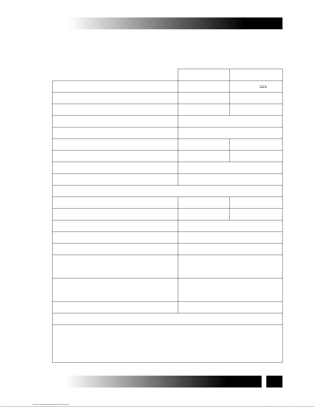
3.3- TECHNICAL DATA
Tab. 1 contains the technical data characterising the actuators.
Tab. 1
Power supply voltage
Absorbed current
Absorbed power with load
Thrust force
Tractive force
Idle translation speed
Duration of idle stroke
Minimum window frame height
(1)
Adjustable stroke end
(2)
10 - 15 - 20 - 25 - 30 - 35 - 40 cm
Type of service
(4)
S
2
230 V - 50 Hz
ACK42
0,32 A
75 W
300 N
300 N
27 mm/s
15 s
H = 800 mm
2 min
Operating temperature
Protection degree of electric devices
Adjustment of the window frame connection
Parallel electric connection of more
actuators on the same window
Only with proper
electronic device
Parallel electric connection of more
actuators on different windows
Actuator weight with brackets
Gross weight
(1)
(2)
(3)
(4)
Actuator distance from the window frame opening hinge
Tolerance on the precision of the output limit switch tripping: +/- 1 cm
The "buzzer" device is enabled automatically and emits a continuous "beep" as long as the
actuator is fed. For further details on its operation see par. 5.6
Service of limited duration according to EN 60034
- 5 + 50 ºCºC
IP 55
10 mm
Yes
(see wiring diagram)
1,7 kg
1,9 kg
ACK44
1,35 A
32 W
17 mm/s
23 s
3 min
Electronics with warning horn to signal to the user the wrong assembling
(3)
9
ACK4
TECHNICAL DESCRIPTION -3
INSTALLATION AND USE ISTRUCTIONS
VER.0.0
REV.11.12
24 V
Class II Class III
Protection against electric shocks
3.5- DESTINATION OF USE
THE ACTUATOR HAS BEEN DESIGNED AND MANUFACTURED TO PERFORM
AUTOMATICALLY, BY MEANS OF A CONTROL DEVICE, THE OPENING AND CLOSING OF
TOP HUNG WINDOWS, BOTTOM HUNG WINDOWS, PIVOT WINDOWS, AND SKYLIGHTS.
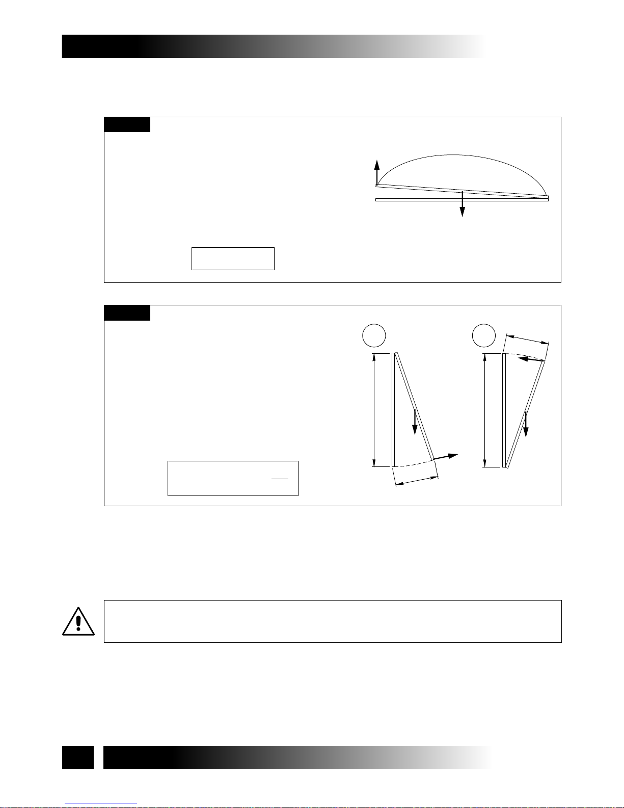
3.4- FORMULAS FOR THE CALCULATION OF THRUST AND TRACTIVE
FORCE
Top hung windows (A) or
bottom hung windows (B)
F = Force necessary for opening or
closing
P = Weight of the window
(only movable part)
C = Window opening stroke
H = Window height
(N)
(N)
(mm)
(mm)
F = (0,54 x P) x ( )
C
H
P
F
H
C
B
P
F
H
C
A
F
P
Horizontal domes or skylights
F = Force necessary for opening or
closing
P = Weight of the skylight or dome
(Only movable part)
(N)
(N)
F = 0,54 x P
10
3- TECHNICAL DESCRIPTION ACK4
INSTALLATION AND USE ISTRUCTIONS
VER.0.0
REV.11.12
Fig. 3
Fig. 4
3.6- USE LIMITS
The actuator has been designed and manufactured exclusively for the destination of
use given in par .3.5, therefore, any other type of use is strictly forbidden in order to
assure in any moment the safety of the installer and of the user, as well as the
efficiency of the actuator itself.
IT IS STRICTLY FORBIDDEN TO USE THE ACTUATOR FOR IMPROPER USES OTHER
THAN THE ONE FORESEEN BY THE MANUFACTURER (SEE PAR. 3.5).
IT IS STRICTLY FORBIDDEN TO INSTALL THE ACTUATOR ON THE EXTERNAL SIDE OF
THE WINDOW FRAME SUBJECT TO ATMOSPHERIC AGENTS (RAIN, SNOW, ETC.).
THE USE OF THE ACTUATOR IN ENVIRONMENTS WITH POTENTIALLY EXPLOSIVE
ATMOSPHERE IS STRICTLY FORBIDDEN.
IT IS COMPULSORY TO KEEP THE PACKAGE AND THE ACTUATOR OUT OF REACH OF
CHILDREN.
3.7- PACKAGE
Each standard package of the product (cardboard box) contains (Fig. 5):
• No. 1 Actuator equipped with power supply cable;
• No. 1 Support (Ref. A);
• No. 1 Bracket for hopper opening (Ref. B);
• No. 1 Small parts package (window connection bracket, nuts, pin and fastening
screws for aluminium window frames) (Ref. C);
• No. 1 Adhesive drilling template (Ref. D);
• No. 1 Installation and use instructions (Ref. E);
• No.1 Safety Plate (Fig. 6).
.
MAKE SURE THAT THE ABOVE DESCRIBED COMPONENTS ARE CONTAINED IN THE
PACKAGE, AS WELL AS THAT THE ACTUATOR HAS NOT BEEN DAMAGED DURING
TRANSPORT.
SHOULD ANY ANOMALY BE DETECTED, IT IS FORBIDDEN TO INSTALL THE ACTUATOR,
AND IT IS COMPULSORY TO REQUIRE TECHNICAL ASSISTANCE FROM YOUR DEALER
OR THE MANUFACTURER.
THE PACKAGING (PAPER, PLASTIC, ETC.) HAS TO BE DISPOSED ACCORDING TO THE
LAWS IN FORCE.
EX
11
ACK4
TECHNICAL DESCRIPTION -3
INSTALLATION AND USE ISTRUCTIONS
VER.0.0
REV.11.12
 Loading...