

Page 1
TK604 user manual
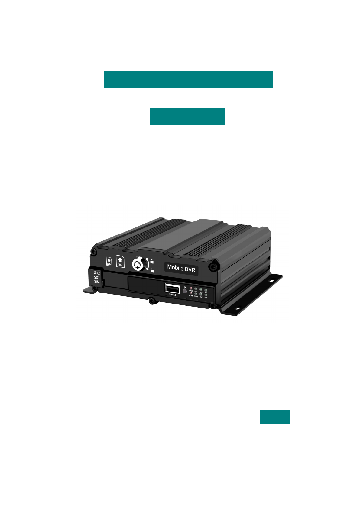
TK604 Mobile SD Card DVR
User Manual
V 1.0 English
Mar 2017
Page 2

Statement
TK604 user manual
Copyright ©2017
All rights reserved.
Without written permission from the company, any individual or
enterprise is not allowed to extract, copy the contents of this manual,
can't disseminate it in any form.
The content of this manual will not be updated regularly due to the product release upgrade or other
reasons.Unless otherwise agreed, this manual is solely used as guidance, and all statements, information and
recommendations in this manual do not constitute any warranties of express or implied warranty。
2
Page 3

TK604 user manual
Catalogue
About the book...................................................................................................................................1
1 product introduction....................................................................................................................3
1.1 product overview ...................................................................................................................3
1.2 TK604 basic working parameter list......................................................................................4
1.3 TK604 main functions of products ........................................................................................5
1.4 Product application program.................................................................................................6
2 Equipment specification..............................................................................................................7
2.1 internal structure of equipment .............................................................................................7
2.2 front panel definition..............................................................................................................8
2.2.1 LED indicator and status description ............................................................................8
2.2.2 Other interface instructions...........................................................................................8
2.3 rear panel definition...............................................................................................................9
2.3.1 the power cable.............................................................................................................9
2.3.2 GPS and WIFI antenn.................................................................................................10
2.3.3 IO Cables ....................................................................................................................10
2.3.4 VGA_Port Cable..........................................................................................................10
2.3.5 4PIN Female Assignments .........................................................................................10
2.4 detailed specifications.........................................................................................................11
2.5 other functions.....................................................................................................................12
3 Host operation guide.................................................................................................................13
3.1 function key of remote control.............................................................................................13
4 System operation\ .....................................................................................................................15
4.1 user login.............................................................................................................................15
4.2 Main menu...........................................................................................................................15
4.3 Search menu.......................................................................................................................16
4.3.1 Video search ...............................................................................................................16
4.3.2 Log Search..................................................................................................................17
4.3.3 Picture Search.............................................................................................................17
4.4 System Settings ..................................................................................................................18
4.4.1 Terminal Settings ........................................................................................................18
4.4.2 Security .......................................................................................................................19
4.4.3 Time Setup..................................................................................................................19
4.4.4 Power management....................................................................................................20
4.4.5 Parameter management .............................................................................................20
4.4.6 Formatting ...................................................................................................................21
4.5 Video Settings .....................................................................................................................21
4.5.1 Record setting .............................................................................................................22
4.5.2 The main stream .........................................................................................................22
4.5.3 Sub-Stream .................................................................................................................23
4.5.4 Time Setting ................................................................................................................23
4.5.5 Storage Setting............................................................................................................24
4.5.6 OSD Setting ................................................................................................................24
4.6 Network Settings (3G/4G machine support).......................................................................25
3
Page 4

TK604 user manual
4.6.1 Center set up...............................................................................................................25
4.6.2 Local Settings..............................................................................................................26
4.6.3 Dial-up Settings...........................................................................................................26
4.6.4 WIFI Settings...............................................................................................................27
4.7 Alarm and peripherals.........................................................................................................28
4.7.1 IO alarm.......................................................................................................................28
4.7.2 Speed alarm................................................................................................................29
4.7.3 The acceleration..........................................................................................................29
4.7.4 Video detecting............................................................................................................30
4.7.5 Voltage alarm ..............................................................................................................30
4.7.6 Serial port Settings......................................................................................................31
4.7.7 PTZ Setup ...................................................................................................................31
4.8 System information..............................................................................................................32
5 Installation of equipment...........................................................................................................33
5.1 Installation Environment ..................................................................................................33
5.2 Installation considerations...................................................................................................33
5.3 Open box inspection ...........................................................................................................35
5.4 Installation instructions of the main engine.........................................................................35
5.4.1 Installation of the whole machine................................................................................35
5.4.2 Alarm input connection................................................................................................36
5.5 Equipment upgrade.............................................................................................................36
4
Page 5

TK604 user manual
Before the speech
Release notes
This manual is applicable to the TK604 multi-function vehicle video model
。
About the book
This manual introduces an integrated surveillance video "4 channel", "wireless data transmission (optional)",
detailed specifications, describes in detail the function of each module of equipment and the use matters needing
attention, describes in detail equipment connectors in the signal definition, detailed describes the equipment
interface definition and the user operation
The book is divided into six chapters
The first chapter Product introduction. This paper briefly introduces the function, main features and typical
applications of products
The second chapter Equipment specifications. Detailed description of each functional module, characteristics,
detailed specifications and usage notes, including surveillance video module and other functional modules
The third chapter Host operating instructions. The use of remote control and the function and use of each
。
。
。
。
display menu are introduced in detail
Chapter 4 Introduction of equipment installation. The appearance of TK604 is explained in detail. Front and
rear panel signal arrangement and connector definition; The signal definition of each external cable; Finally, product
installation instructions
。
。
1
Page 6

TK604 user manual
Important to keep the safety and prompt
!Note
Please read this manual before installing and using this product,
Carefully before be sure to read the following warnings:
installation. Safe
Deposit of this manual
For future reference
:
1. Please handle the transportation gently。
2. All installation and maintenance must be carried out by trained
qualified persons。
3. This product shall not be installed on vehicles for long periods of
rain or other liquid erosion。
4. Installation and all materials must be able to withstand the weight of
the fuselage.
5. Keep the fuselage away from heat, dust and strong magnetic fields.
6. No weight should be placed above the equipment, and no debris
should be piled up in the surrounding 50cm.
7. The vehicle shall not flush the equipment directly when cleaning.
8. Equipment output power shall not be used for the replacement of
the equipment.
9. No finger or foreign material is inserted into the slot of the
equipment during operation.
10. Please do not open or disassemble the equipment without
professional guidance.
11. Do not change any modules under the charge of the host.
2
Page 7

TK604 user manual
1 product introduction
1.1 product overview
TK604 is a cost-effective and scalable device for on-board video monitoring and remote monitoring and
development. IT adopts high speed processor and embedded operating system, combining with the most advanced
H.264 video compression/uncompresses technology, network technology; GPS/BD positioning technology in the IT
field.TK604 supports 4-way video and video. TK604 - - 4CH 720P can be realized with the frame format of the video,
car information records and wireless data upload, cooperate with the center software which can realize the alarm
linkage of central monitoring, remote management and playback analysis based on a central database. The product
has a simple appearance, strong anti-vibration, flexible installation, powerful function and high reliability.
The details are as follows
USES the int ernational mainstream H. 264 coding format, high compression ratio, image is clear, of disk space is
little;
using SD card as storage medium, easy to read data, fast;
video using general FAT32 / special file format, support the market mainstream H264 player p lay;
+ 6 v ~ + 36 v wide voltage design, suitable for all kinds of models;
support 4 CH 12 v / 0.5 A power output, for A peripheral power supply;
support 4CH alarm input;
professional replay analysis software, GPS/BD to track, the car status, speed and sound view as synchronous
playback;
centralized management software, support the vehicle image and alarm information real -time transmission, etc.
small size: the whole machine size (167) x (55) x (150) mm, weight 0.77 KG
:
3
Page 8

TK604 user manual
1.2 TK604 basic working parameter list
The basic working parameters of the TK604 are like tables
Working
Projects
Parameters
The input voltage is +6V ~ + 36V, the voltage is lower than 6V for a
long time, or long-term higher than 36V, the device automatically
The power input
Output voltage 12V Output voltage 12V (+ /-0.2 V), maximum current 2A。
Car key signal
Video input
impedance
Video output 1Vp-p Output a 1p-p CVBS analog signal。
6~36V
shutdown, enter protection mode, and have abnormal power loss
protection function
≤6V Engine key off。
≥7.5V Engine key open。
75Ω Each video input impedance are 75 Ω road。
1。
Description
alarm output
SD card
interface
The USB
interface
Working
temperature
0 minus 2V is low level。
The I/O port
Above 5V is high level。
The AD port Enter 0-36 v。
1. Compatibility with common brands。
2. Double SD bayonet
3.Live unplug is not supported. When the panel is locked on the
control switch, it can lock the SD card and prevent the plug
1.Compatible with various commercial usb drives。
-25 ~ + 60 ℃ ℃ Refers to the ambient temperature under good ventilation conditions。
2.Live out plug. When the device file is transferred, unplugging the
USB key may break the data in the U disk。
4
Page 9

TK604 user manual
1.3 TK604 main functions of products
Main functions of TK604: video monitoring .Its main function list is shown in table 2.
Systems Function Instruction
Video channel
resolution
Image quality
1 to 4 channels are optional
Supports CIF, D1 720P resolution video
It is divided into 1-5 level and the highest quality
Can overlay various characters, such as date, time, GPS latitude, channel
OSD
ID, etc
Video subsystem
Playback
subsystem
Loop recording
Video mode
Preview
Disk cover
Video search
The playback
Support double SD card cycle or mirror recording, and cycle delete
Support startup video, timing video, alarm video and manual recording
Support single screen and four screen preview
Support disk auto coverage
Support a month within any date, time - time search
Support the alarm point search and time point search
Supports single-channel to four-way comparison playback
Support fast forward, fast forward, fast forward, quick return speed support 2,
Alarm
Parameter
Settings
Network (optional)
Inputting
Switch machine
Networks
4, 8, 16 times speed
4 circuit alarm input can be selected, whether to trigger the alarm video can
be selected
The alarm video supports the first 10 seconds and the video duration of the
video is matched
Delay switching machine support
Support key switch machine and time switch machine
1.Automatic report of vehicle information
2.Direct video to the server via 3G/WIFI network
3.Remote playback through the client connection server
5
Page 10
TK604 user manual
1.4 Product application program
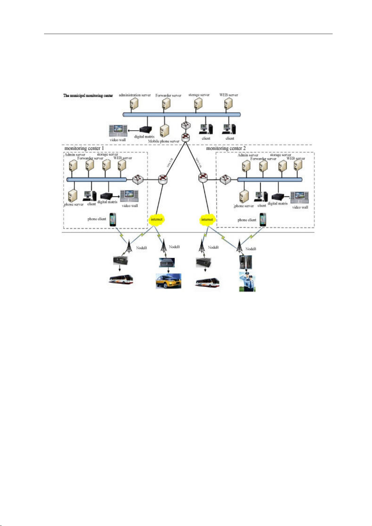
TK604 products are suitable for video surveillance and remote monitoring of all motor vehicles. The general
application process of the TK604 is as follows
:
Figure 1. The TK604 application network diagram
6
Page 11
TK604 user manual
2 Equipment specification
This chapter introduces the function overview, characteristics, detailed specifications and precautions of the
equipment
。
2.1 internal structure of equipment
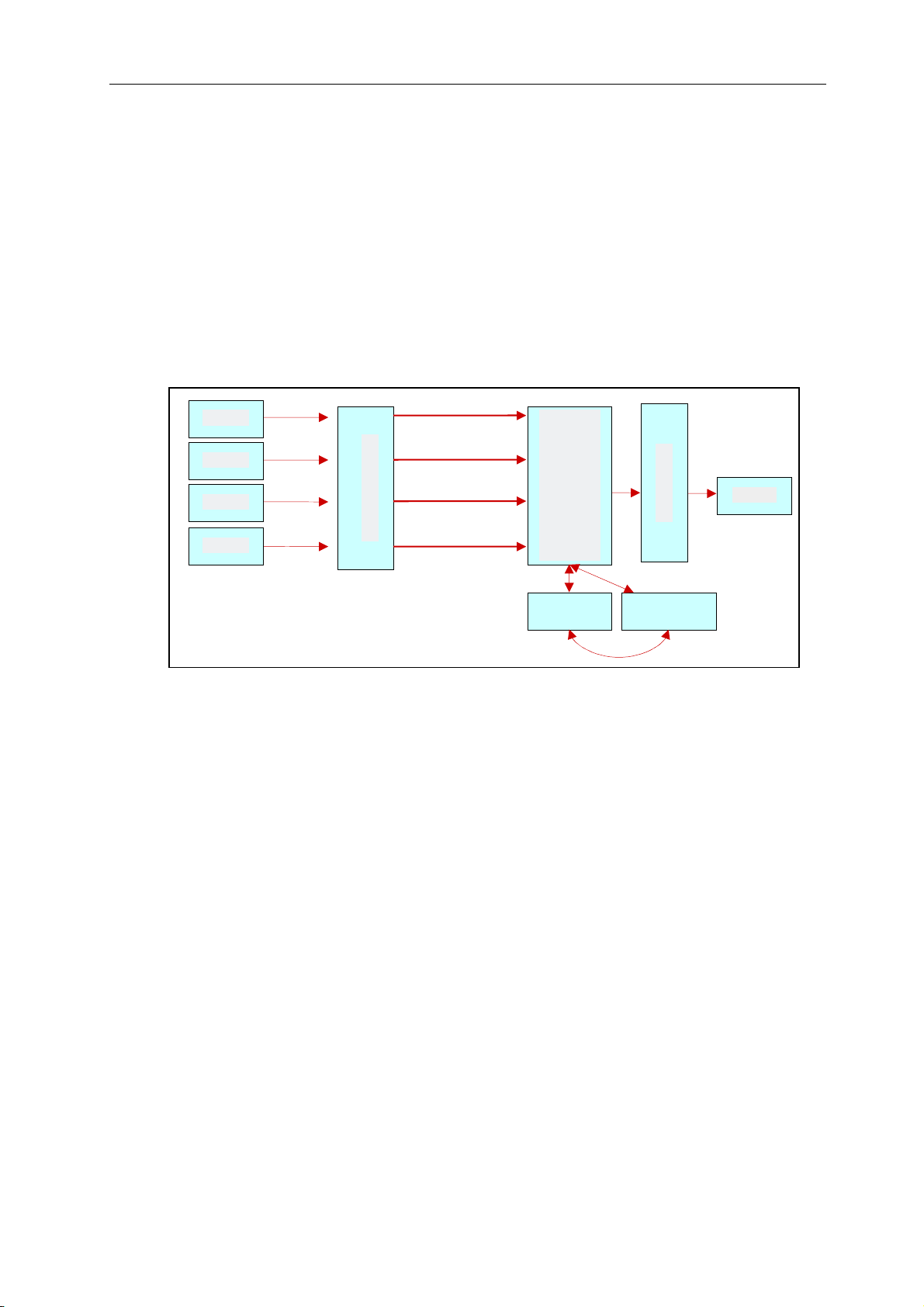
The TK604 is integrated with a set of hardware video encoding chips that consume very little system resources.
Work flow is
:
camera
camera
camera
camera
Audio/video input
Master chip
Video output
display
Compati
USB
Video recording, :
Through audio and video camera input, and then in the main chip compressing storage and preview the output;
Local and remote playback:
1. Local playback
Master control chip from the storage device for video files;
decoding broadcast, the audi o and video analog signal;
2. Remote playback
through the client connect to the server for remote playback;
7
Page 12

TK604 user manual
2.2 front panel definition
The front panel is shown below
:
2.2.1 LED indicator and status description
【PWR】
properly
【SD1、、、、SD2】
means no SD card or SD card abnormality
Power input status indicator light. The light indicates that the system power is working
;
SD card work lamp. The light indicates that SD card works normally. Lamp extinguishing
【HOT】
【4G】
registered failed lamp flicker
【ALM】
【BD】
【REC】
Hard disk heat lamp, lower than 0 ℃ automatic heating, heating normally on a red light
Network indicator light, when registered successfully, the network light is long, unregistered or
;
alarm light, the system has alarm lights, no alarm when the lights went out
positioning to BD signal lights, not positioning or lights flashing when positioning failure
video work indicator light.The LED light indicates that the video is currently being recorded
2.2.2 Other interface instructions
【【【【Panel lock】】】】
【【【【SD1、、、、SD2】】】】:
【【【【SIM】】】】
【IR】
Remote input to receive remote control signal
Control the device switch machine, lock the SD card at the same time, prevent the plug
SD card slot for recording video data, configuration file update and upgrade
3G/4G phone card slot
;
;
;
;
;
。
。
【【【【USB 口口口口】】】】:
8
Import and export data or upgrades for the U disk
。
Page 13
TK604 user manual
2.3 rear panel definition
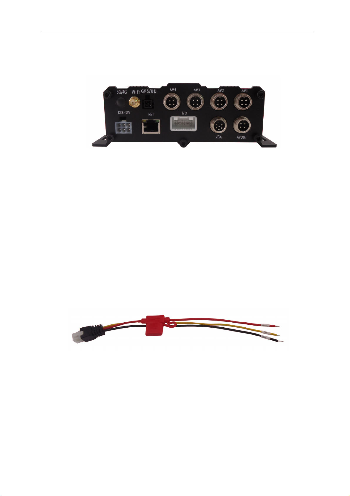
The following figure shows
【DC8-36V】
to the negative pole of the on-board power supply, and the yellow line is ACC signal line. When you need
to set up a timer or fire video, pick up the ACC line
【AV 1~4】
:
Power interface, red line to connect the vehicle power anode; The black line is connected
The four-channel audio and video input interface
【【【【VGAOUT】】】】VGA Format output and Audio output.
【【【【A/V OUT】】】】1Vp-p CVBS video and Audio output.
。
;
【I/O】
【3G/4G】
【WIFI】
Alarm input interface,and
3G/4G antenna interface
WIFI antenna interface
Expansion interface;
; 【NET】
RJ45 network interface
; 【GPS/BD】
;
GPS/BD antenna interface
。
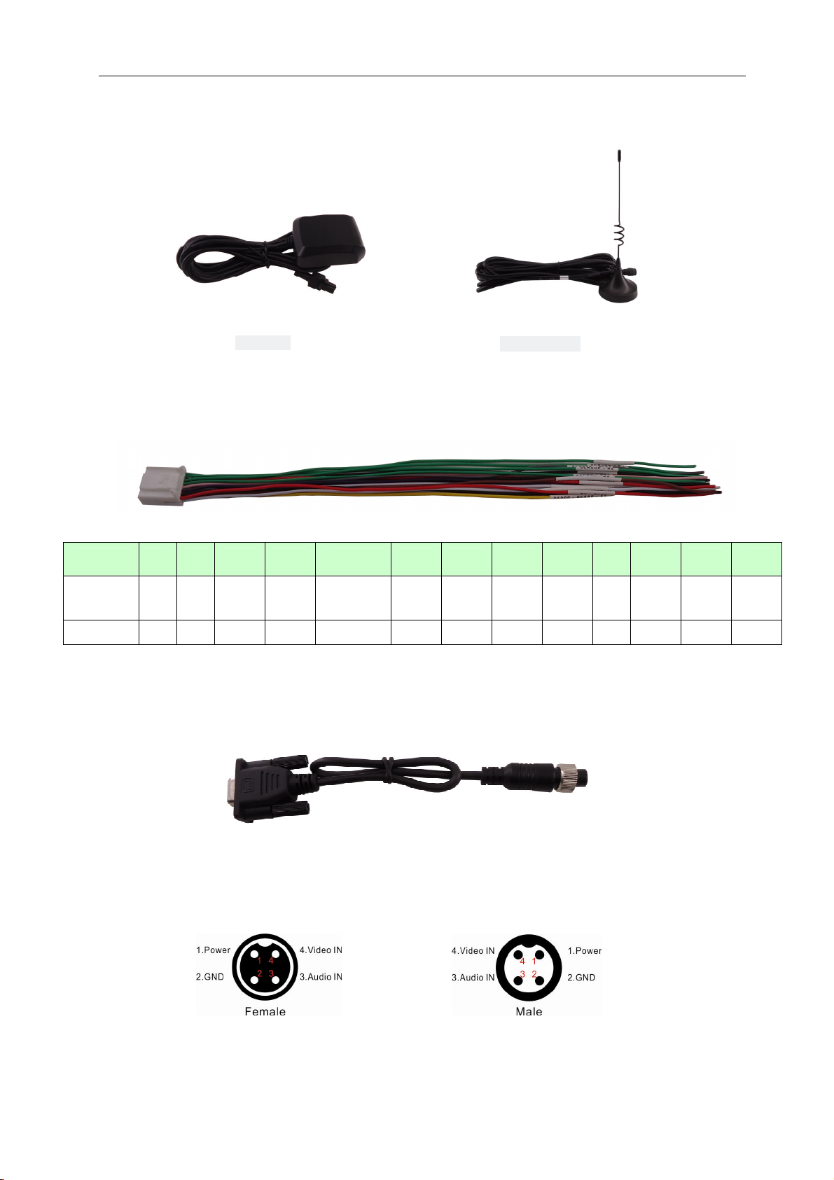
2.3.1 the power cable
Figure 14 shows the power line, with a variety of color plugs on one end, and then the 3PIN connector on the rear
panel of the device. Red lines and black lines are directly received from the car's battery. The red line is connected
to the positive pole and the black line is negative. The yellow line contacts the fire line, the host equipment
automatically opens after the car turns the key, and shuts off after turning off the car key. The yellow line picks up
the gear when the car keys turn on all the dashboard lights (that's the stall before the car starts the motor).
Note:
1) Make sure the voltage of the battery is between 6V - 36V before connecting, otherwise it will burn the equipment.
2) After connecting the line, pay attention to the insulation between the power cord and prevent the power line from
short-circuiting the battery.
3) The yellow line must be connected to the ignition line, otherwise the device will not support the delayed shutdown,
and the final video, video, will be lost.
9
Page 14
TK604 user manual
4PIN Female Assignments
The GPS
2.3.2 GPS and WIFI antenn
WIFI Antenna
2.3.3 IO Cables
Number 1 2 3 4 5/6/7/8 9 10 11 12 13
Assignments
Color Red Black Purple Pink Green White Brown Yellow White Black Gray Black Red
5V_
Out
Gnd Mic+
Aud0_
Out
Sensor_IN1,
2,3,4
RS232
_RX1
RS232
_TX1
RS485+ RS485
-
Gnd
14 15 16
Sensor
_Out
Gnd
2.3.4 VGA_Port Cable
12V_
Out
2.3.5
10
Page 15

TK604 user manual
2.4 detailed specifications
The detailed specifications of the TK604 video function are shown in table 3.
TK604 video features detailed specifications
projects
The operating system
Graphical operation
interface
Support language
Safety management
Video input,
output
OSD
Video
compression
format
Double stream support
Video
and
preview
Preview
function
Frame rate
resolution
describe
Linux
The remote control sets the system parameters through the external
display screen
Chinese, English, traditional (optional)
User password, administrator password two level management
4. Video input, 1 VGA output, 1 channel video output;1.0 the Vp - p, 75 Ω
Character superposition function, time date, vehicle ID and other
information image overlay
H.264 compression coding. Use Hisilicon high performance processor
Single path and 4 screen splicing preview, support event trigger full screen
and splicing switch display function
PAL: 100 frames per second, maximum 25 frames per second; NTSC: 120
frames per second, maximum 30 frames per second
Can support 4CIF, 4D1, 4 AHD720P coding for mat
.
audio
video
mass
Bit rate
Audio input
output
Compressed
format
A storage
medium
File
format/system
Video strategy
Video retrieval
Video playback
Alarm input 4 circuit switching signal alarm input alarm
Alarm video
、
1 to 5 video can be matched, the optimal level 1, the lowest level 5
CIF: 300Kbps ~ 1200 BPS, 8-grade rate optional
HD1:500Kbps ~ 1500Mbps, 8-level code rate optional
D1:600Kbps ~ 2048bps, the 8-level code is optional
X720p, 720-1024
4 channel input, 1 output, 1 VGA output
Adopt H. 264 encoding
Support SD card, SD card maximum support 128G;Support USB interface
for data export/mouse operation
H.264/FAT32,
The default startup video is to support timing video, alarm and event
trigger video and manual recording
It can be searched according to video time, video type, video storage
device and other conditions
Support the native playback, the maximum support of 4 channels
synchronous playback, and analysis of the vehicle information in the
document
Support fast forward, quick return, play, pause control, support 2, 4, 8, 16
times fast forward or fast back, support select time playback control
Pre-recorded function, the first 10 seconds pre-recorded, the video length
of the time of the police can be matched, 5 seconds ~ 3600 seconds
Special file system
11
Page 16

TK604 user manual
Storage space
alarm
Alarm function Video lost the alarm
Location (optional) Extensible support for GPS, BD module integrated antenna
Mobile network (optional) Can support 3G, 4G, WIFI
System upgrade SD card/USB upgrade
Power
supply
and
power
consump
tion
environm
ent
Power
management
Input voltage DC:+6V ~ +36V
Output voltage +12V@5*0.5A;
Power
consumption
temperature General: -25 ~ + 60 ℃ ℃ Working
humidity 10% to 95%
Support disk space alarm function
1. ACC switching machine
2. Delayed shutdown
3. Time switch machine
It has overload protection, under voltage protection, short circuit
protection, anti-grafting protection, etc
Normal working condition < 10W;0W in standby mode
Pay attention to
::::
Reducing the number of video channels, reducing the frame rate, decreasing image
quality, lowering the resolution can reduce the storage capacity, and the user can adjust the
video parameters as needed。
2.5 other functions
In addition to the above main functions, the TK604 also designed other functions to make it easier for users to
use. Detailed specifications for other functions are shown in table 4.
Table1. Specifications for other functions of the TK604
Class
Equipment self-check
(optional)
1.The screen displays the current state of the system (if the module exists), including:
A) status of GPS/BDS module and whether there is a signal;
B) status of 3G/4G/WIFI module, SIM card status, signal strength, dial-up status and
connection status;
2. The front panel of the host has a key status indicator. The status of equipment can be
judged by indicator light: Power, disk read and write with fault, video, network transmission
and failure;
Detailed specification
12
Page 17

TK604 user manual
3 Host operation guide
3.1 function key of remote control
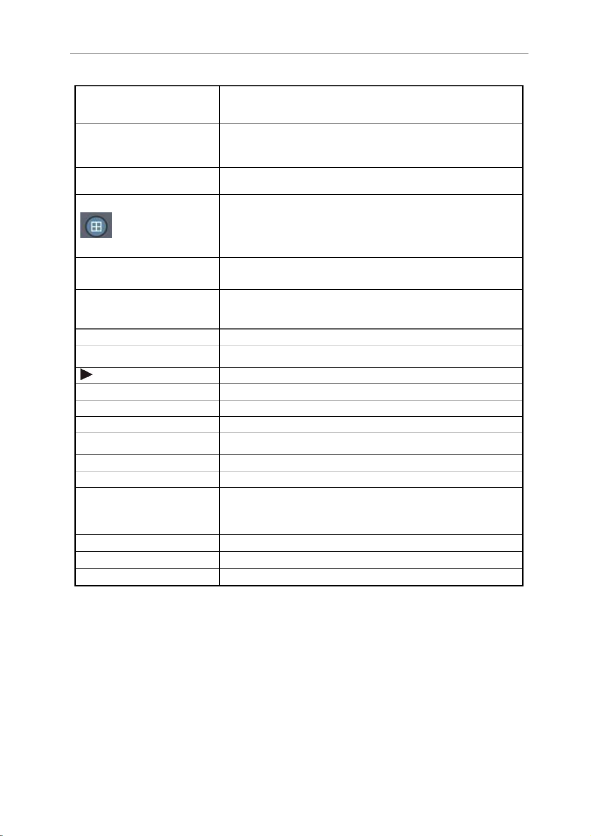
There is no control button on the MDVRS panel at the peak hour, which requires remote control operation. The
buttons and functions are as follows
The number keys area:
。
【
0-9
】
Key: select the number when setting parameters; During preview and playback, "1, 2, 3, 4" is used
for channel switching
【
++++
】、【
【
ENTER
【
LOGIN
【
RETURN
In playback, press ENTER to display the parameters in the OSD menu as long as these parameters are set to
display on the screen
。
----
】
Key: adjust the number of additions and subtracting
】
Key: when setting parameters, it means selecting and saving
】
Key:
Landing system parameter setting keys.
】
Key:
Exit to the preview or return to the previous menu.
。
。
。
13
Page 18
TK604 user manual
Table 4-1: detailed description of the function key of the remote control
The switch machine key
LOGIN
INFO Check the information
Numeral 1,2,3,4
RETURN
PAUSE / STEP
GOTO When playing, press it to jump to the specified time and play
FRAME Press FRAME to play FRAME by FRAME
(PLAY)
FWD
REW
■
Press this button twice to restart the device (soft start button)
(note: you can't use it now)
When you have a password, press "login" to enter your password.Please
keep the password in mind since the device has no reset function.
Switch between channels 1, 2, 3, 4
Press the number keys 1, 2, 3, 4, you can switch to channel 1, channel 2,
channel 3, channel 4.
Return to the previous level directory, exit the Settings menu and return to
the screen
When the video is played back, press STEP and continue to play. Press
PAUSE, PAUSE PLAY, press PLAY button, PLAY normally。
Play button. (when paused, it will display a static image)
Video playback, fast forward, four levels: 2X, 4X, 8X, 16X
Video playback is slow, 4 levels: 2X, 4X, 8X, 16X
Stop the manual video key
●
NEXT Switch to the next page or the next video file when playback
PREV Go to the last page or the last video file when playback
AUTO 、 PRESET 、 ZOOM+/- 、
FOCUS+/- 、 IRIS+/- 、 PTZ 、
PRESET、RECALL、BRUSH
F1 Solid test
AUTO An instruction display area in the command platform
F2、F3 F2 and F3 are backup keys (reserved for future use)
Open the manual video key
Function control key of cloud platform
14
Page 19
TK604 user manual
4 System operation\
4.1 user login
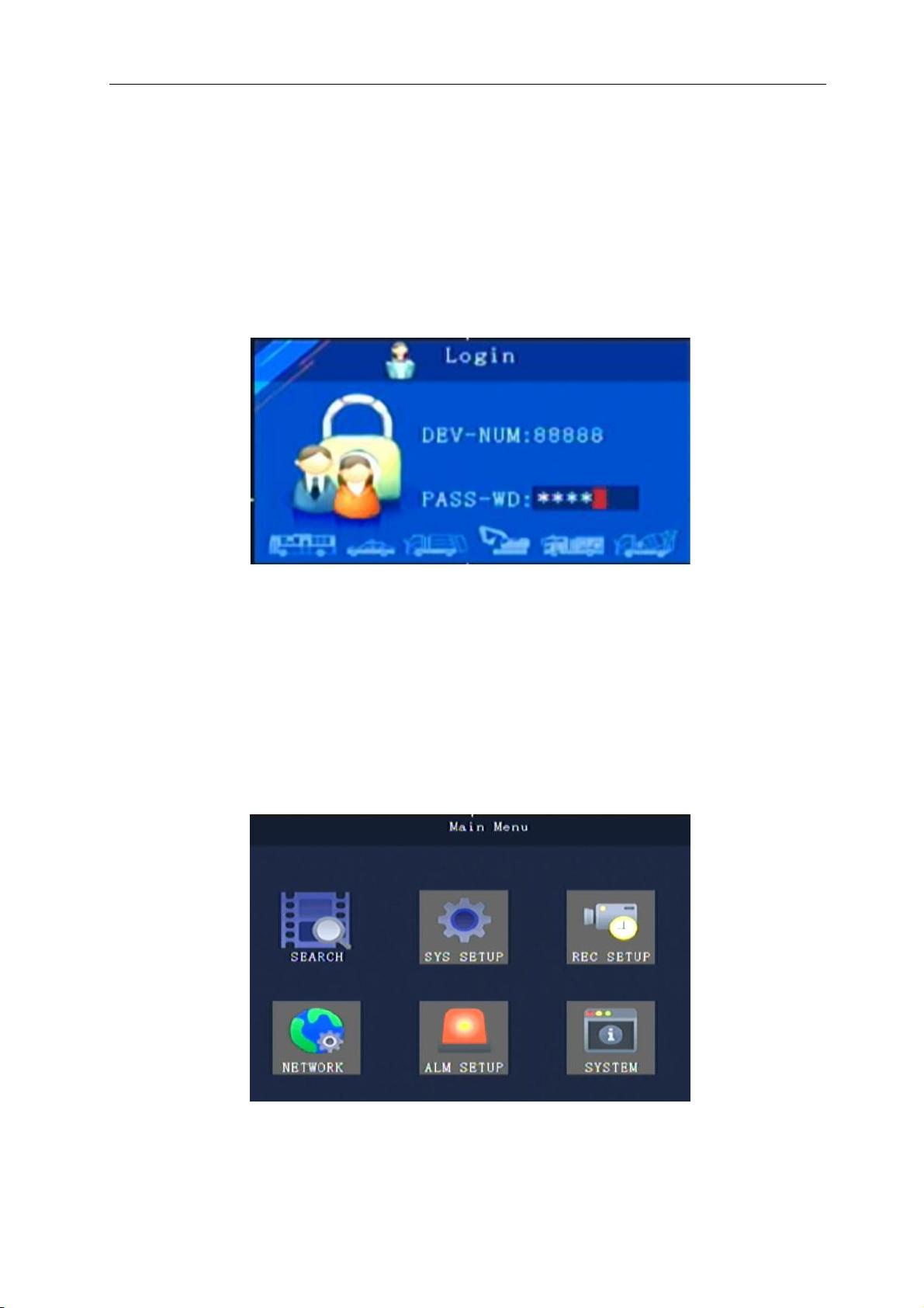
Password when the switch is set to "off”: the host starts press [OK] to directly enter the system main menu.
When the switch is set to "open" password: host starts press [OK], need to input the correct password, the
cursor to "log in" column, press the "OK" key, can enter the system main menu.
The administrator's default password is 888888 (or device number, which is available before the password is
changed);
User default password is 111111, only have query authority;
4.2 Main menu
After user login, enter the main menu interface. Main menu includes: inquiry, system management, video
setting, network setting, alarm and peripherals, system information, as shown below:
15
Page 20
TK604 user manual
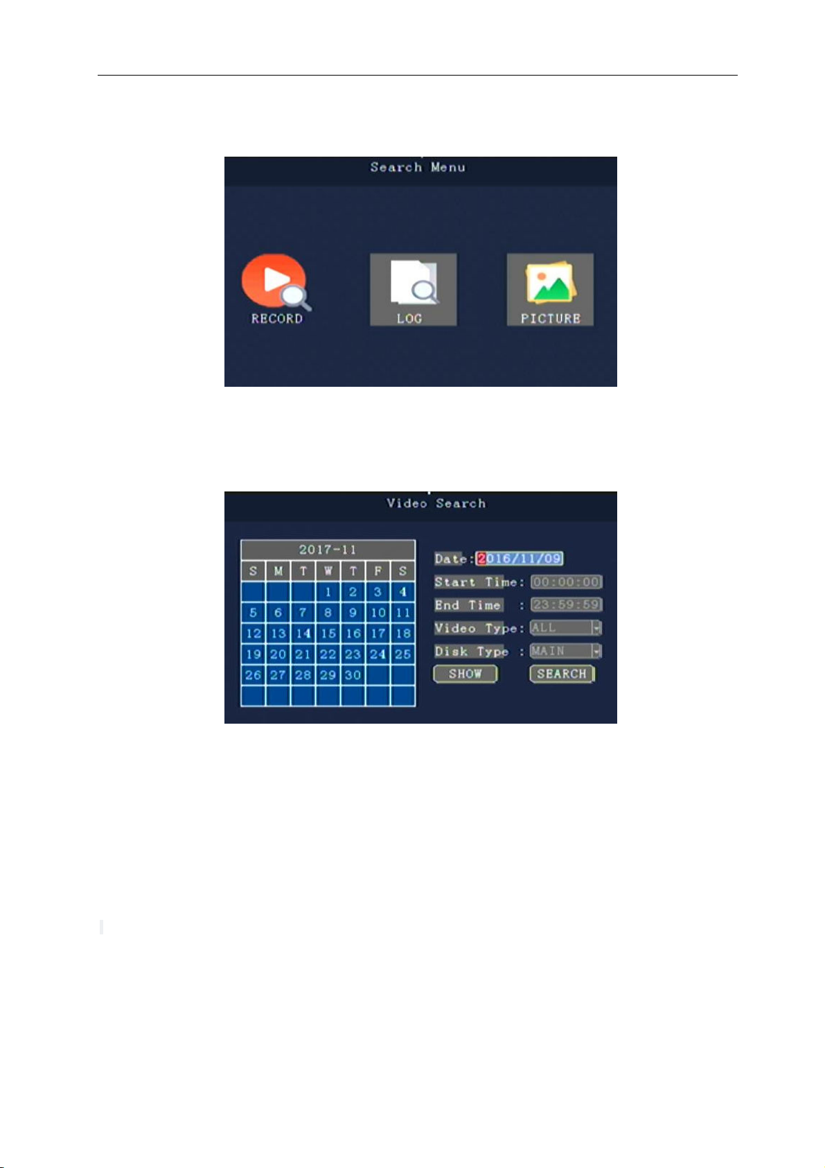
4.3 Search menu
Search menu includes: Video search, Log query, Image search.
4.3.1 Video search
The color block indicates that the current date and current time exist video files
"Date”: enter the date by the numeric key, by default for the day.
"Start time”: press the number key input time, the default is 00:00.
"End time”: press the digital key input time, by default of 23:59:59.
"Video type”: press [OK] to select the query type: all video/alarm video. The system defaults to all videos.
"Disk Type”: press [OK] to select: all disks, disks 1, disk 2.
Search: the cursor moves to the "search" button and press [OK] to enter the search results interface.
The search result interface is shown as below:
according to the direction key choose to view the video data, press + - can be fast flip, press after the play button to
start playing the video information, click "EXIT" button to return to the higher level menu.
according to the direction key choose "home page", "back", "next page", "page", at the end of the press [OK]
shows information page.
* Special tip: after selecting the file, press the PLAY button to PLAY the playback.
16
Page 21
TK604 user manual
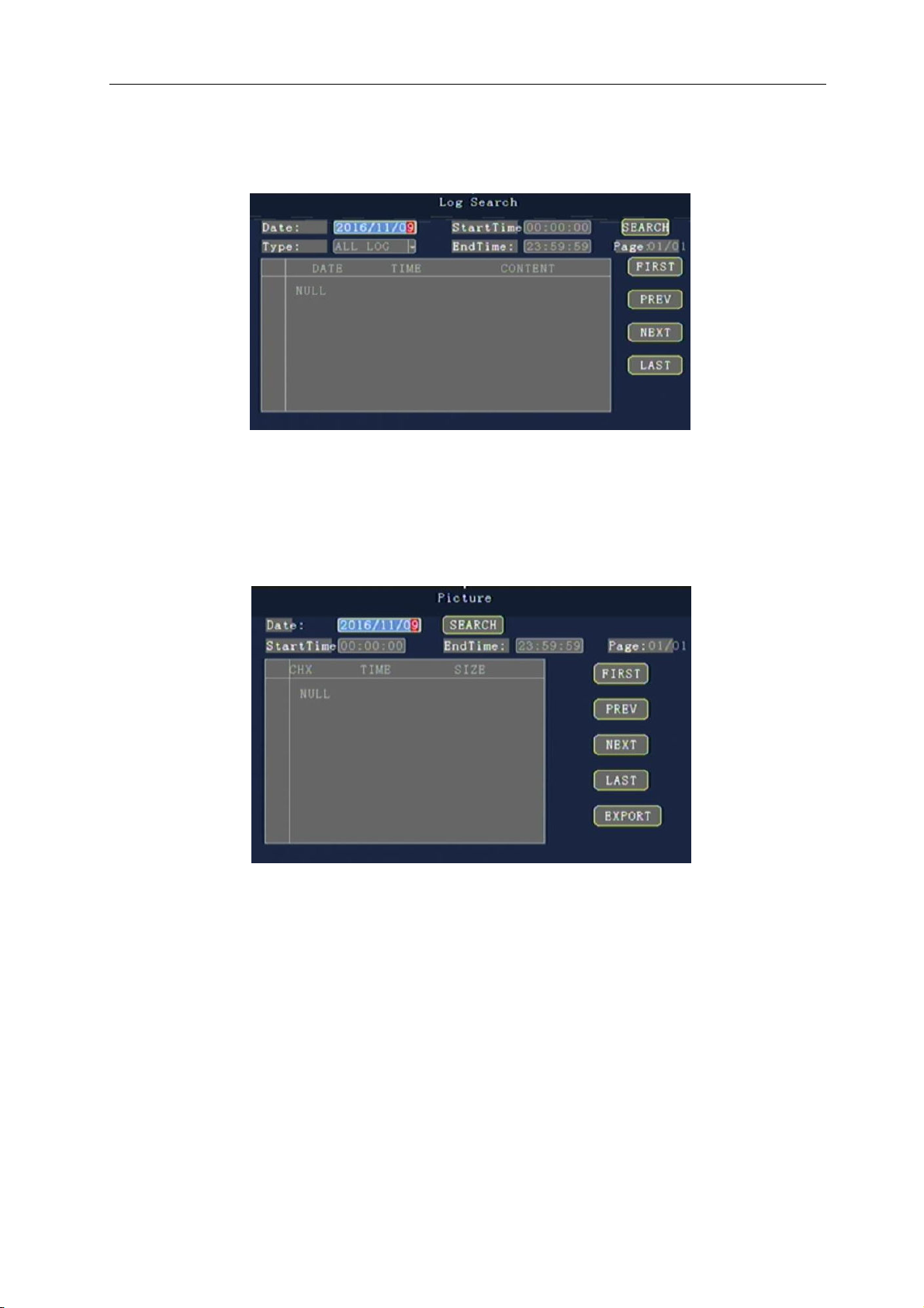
4.3.2 Log Search
This menu queries the device operations and logs for the work
4.3.3 Picture Search
This menu queries the device operations and pictures for the work
17
Page 22
TK604 user manual
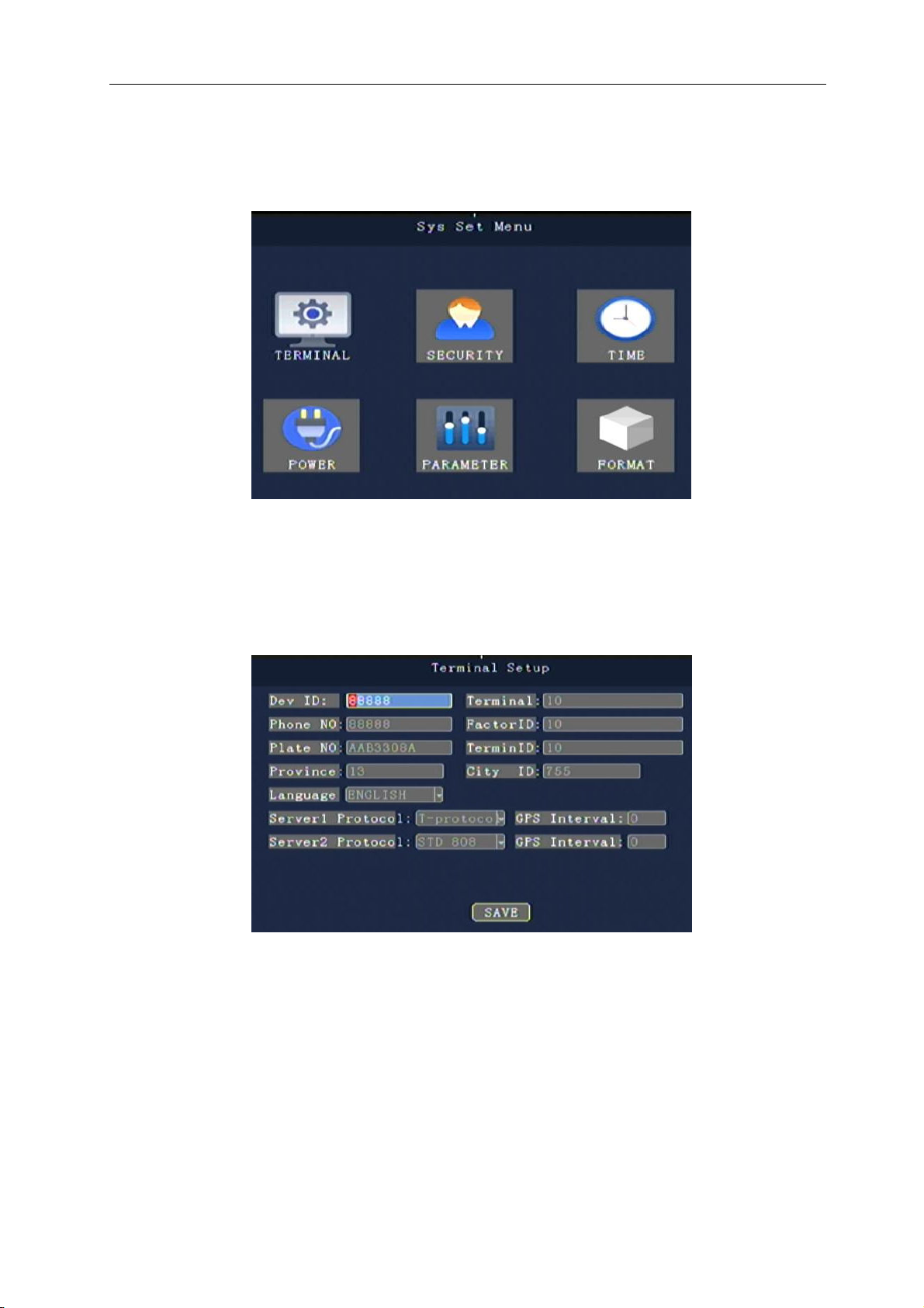
4.4 System Settings
The system Settings menu includes: terminal setting, user management, system clock, power management,
parameter setting, formatting (after menu setting and modification, save after selection).
4.4.1 Terminal Settings
Can be set up by remote control input: device number, phone number, license plate number, provincial ID ,
terminal model, vendor ID, terminal management of equipment (data can be in accordance with the U.S. standards,
can use Chinese input soft keyboard input)
18
Page 23
TK604 user manual
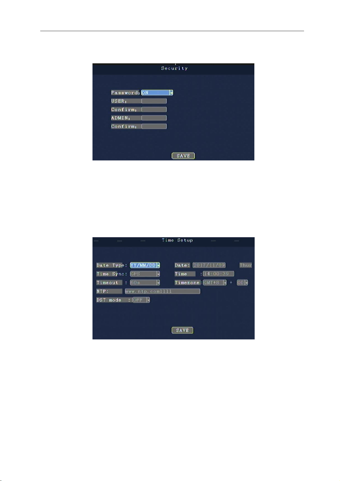
4.4.2 Security
"Password”: can open or close the password verification function that enters the menu
Modify or set the user and administrator passwords by remote control
4.4.3 Time Setup
This menu sets the device date time and other parameters
"Date Type”: you can choose different date formats
"Date”: enter the day by number
"Time Sync”: you can choose the time mode: GPS, NTP, etc
"Time zone”: the time zone that can set the location of the device
"Time out ”: the time to automatically exit when the remote control is not operated
"Time”: manually enter the current time by number
19
Page 24
TK604 user manual
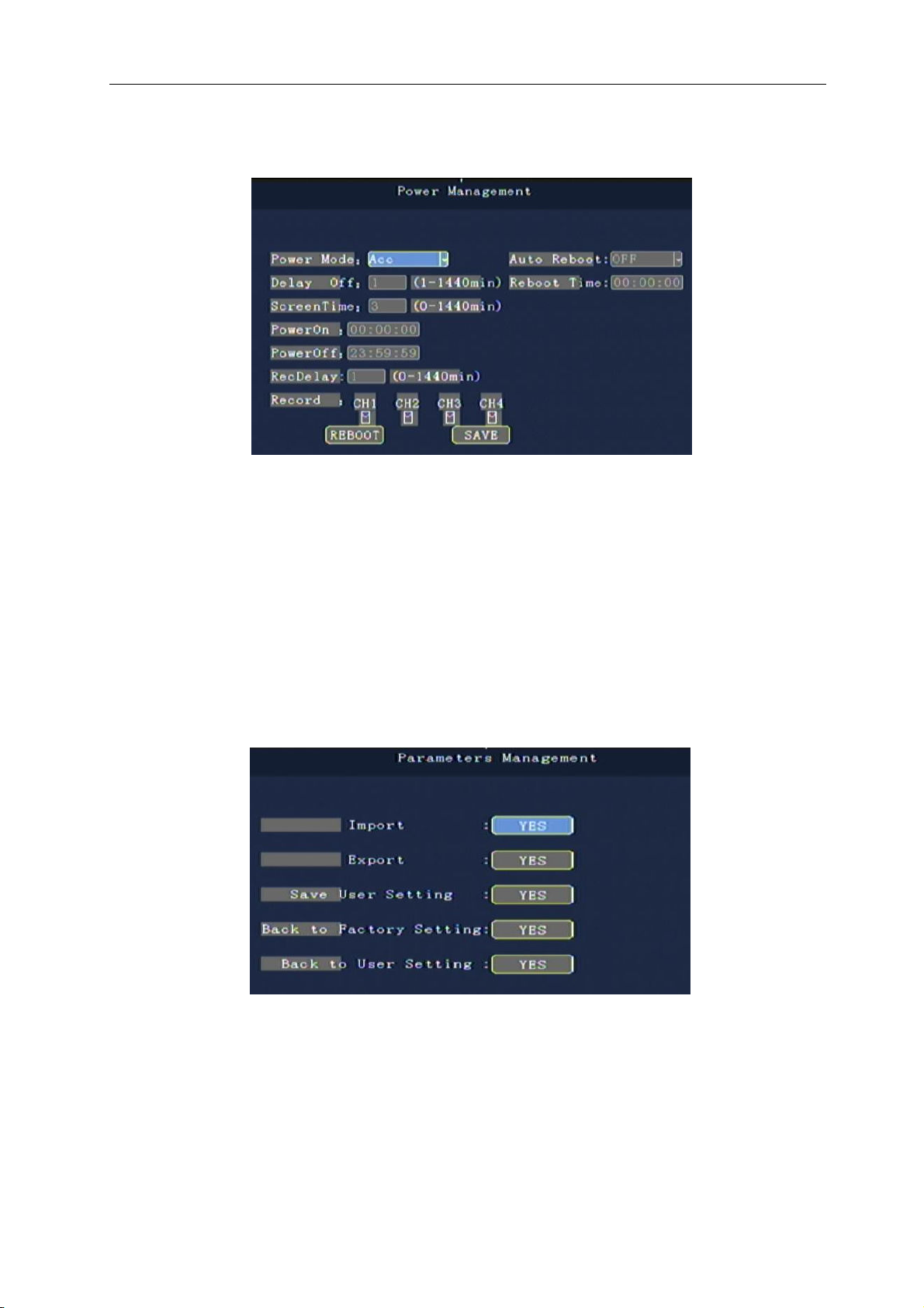
4.4.4 Power management
This menu sets the device's power management mode
"Power mode”: according to the number key selection type, the default is the ignition mode (ACC)
"Delay off”: press the number key input time, the default is 5 minutes, can be set to 1-1440 minutes
"Screen time”: saver delay the default is 60 minutes by the numeric key input time, and can be set to 0-1440
minutes
"Reboot time”: according to the number input time, set the time
"Power off time”: according to the number input time, set the time shutdown time
4.4.5 Parameter management
"Parameter import”: import the configuration information on the current memory to the current device. Import the
installed system configuration parameters and restore the factory to the factory.
"Parameter export”: export all configuration information of the current device to the memory.
"Back to Factory setting" : restore all Settings of the device to the default state. This action removes all Settings for
the device.
20
Page 25
TK604 user manual
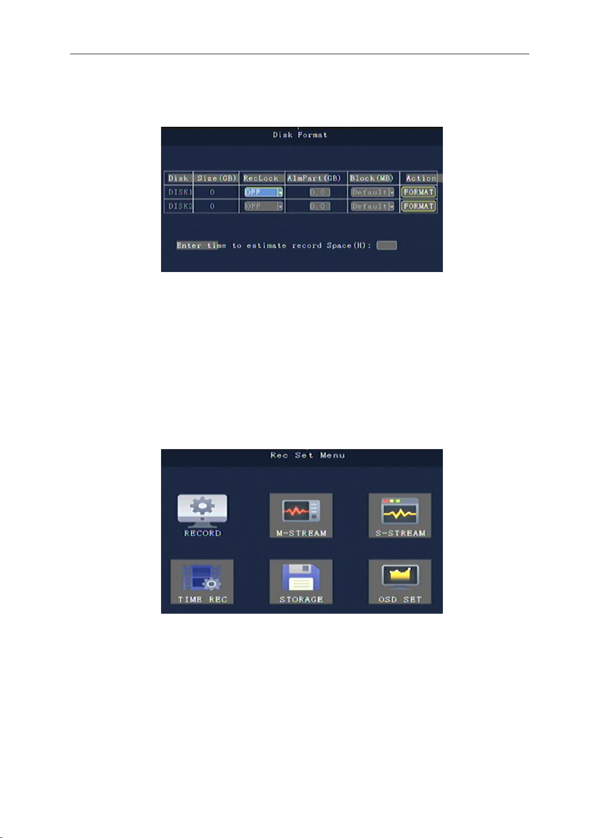
4.4.6 Formatting
Format disk selection (the device is automatically formatted when the device is started, and no manual
formatting is required)
Note: installing a number of devices and each device is set at the same time, please use the configuration of import
and export, namely setting up a device, export the configuration file, and then imported into the other devices can be
realized each device configuration is the same.
4.5 Video Settings
The video Recording Settings menu includes: Record Settings, main streams, sub- streams, main streams,
timed videos, storage, OSD Settings.
21
Page 26
TK604 user manual
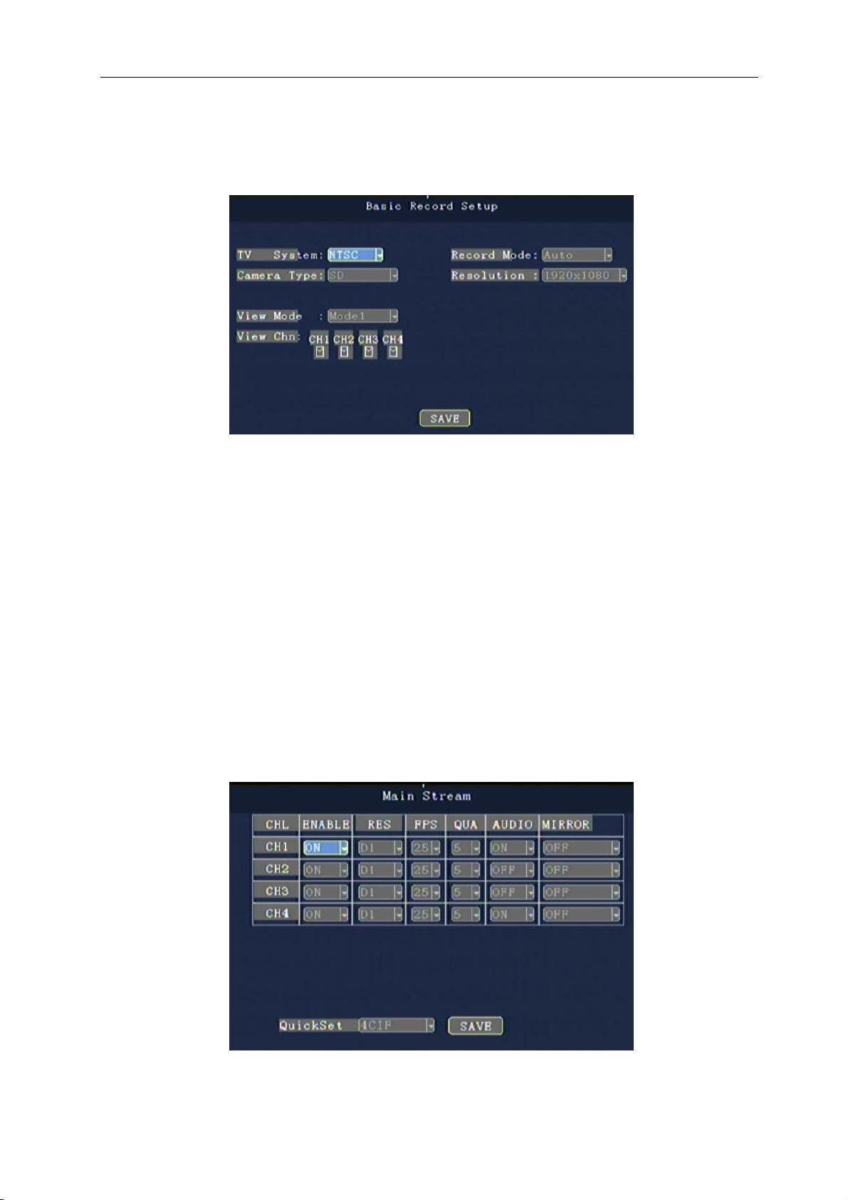
4.5.1 Record setting
This menu sets basic audio and video input signals, video parameters, and power-on image segmentation
mode.
When the user first makes the machine, the following operation is required (otherwise the video camera does not
have the video image output).
“Camera type”: access to the native camera type, press [OK]
Hd mode: using the AHD camera (1.3 megapixels)
Sd mode: use analog camera.
Hybrid model: CH1 and CH2 are using the AHD camera, CH3 and CH4 using analog camera
"TV System”: PAL/NTSC, press [OK] to select.
"Record mode”: starting/timing/alarm recording, press [OK] key selection.
"Resolution”: can choose VGA out CIF, HD1, D1, 720P video resolution.
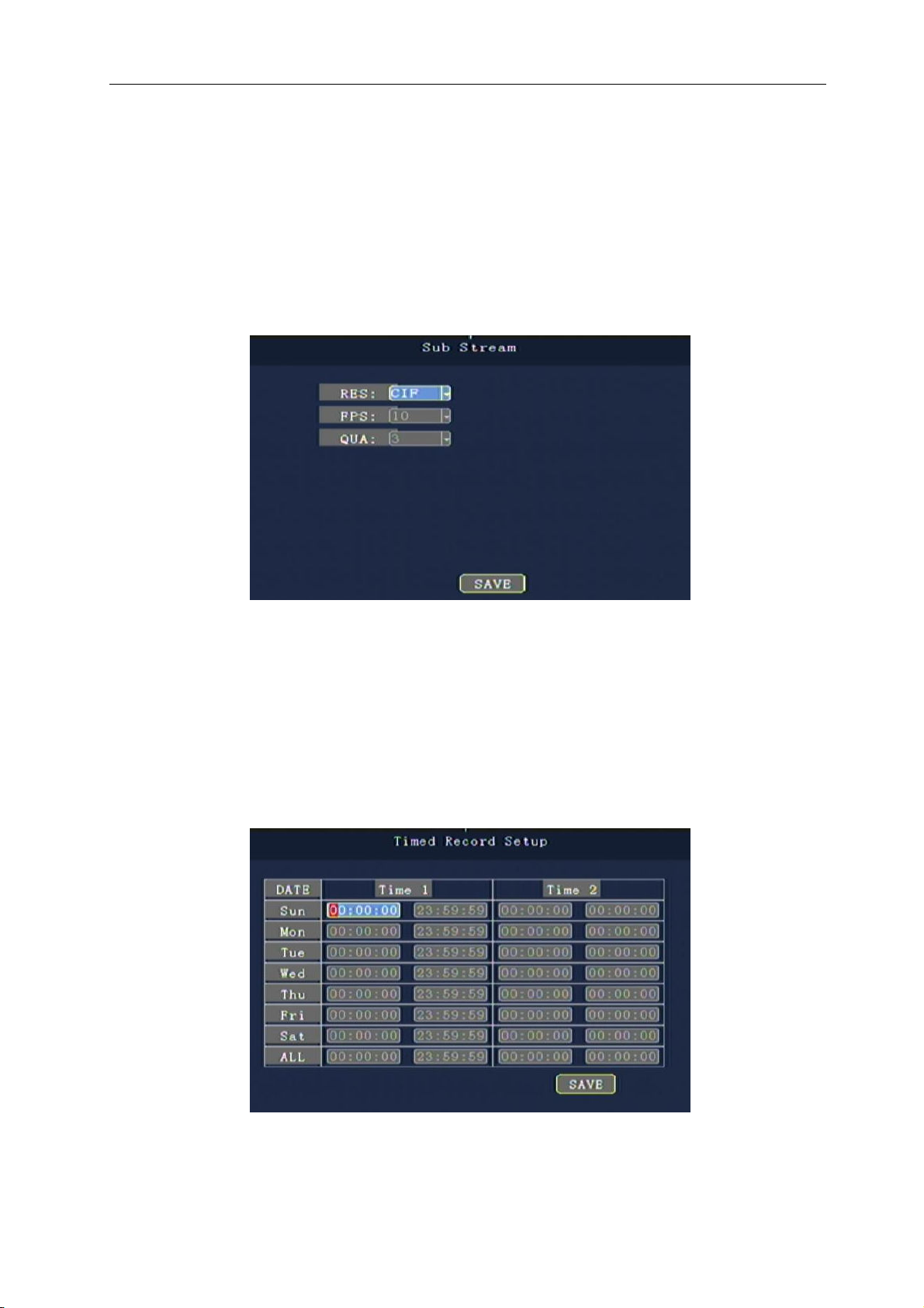
4.5.2 The main stream
This menu is used to set the code stream and clarity of the video channel
22
Page 27
TK604 user manual
"Enable”: to open or close the channel video function, press [OK] to select.
"Resolution”: can choose CIF, HD1, D1, 720P video resolution, press [OK] key selection.
"FPS”: can choose 1-25 frames (P), 1-30 frame (N mode) channel video frame rate
"Picture quality" sets the video quality of different resolutions, four adjustable
"AUDIO" sets the recording sound on or off
4.5.3 Sub-Stream
This menu is used to set parameters for the transport sub stream
"Resolution" sets the resolution of the transmission, and press [OK] key input
"FPS" sets the number of frames in the transmission, and press [OK] key to enter
"QUA" sets the quality level of transmission and press [OK] key input
4.5.4 Time Setting
Can set the time period of time video, can set up 2 times each day
Move the cursor to "timed video" and press [OK] to enter the following time setting
Timed recording starts before the timing video stops.
23
Page 28
TK604 user manual
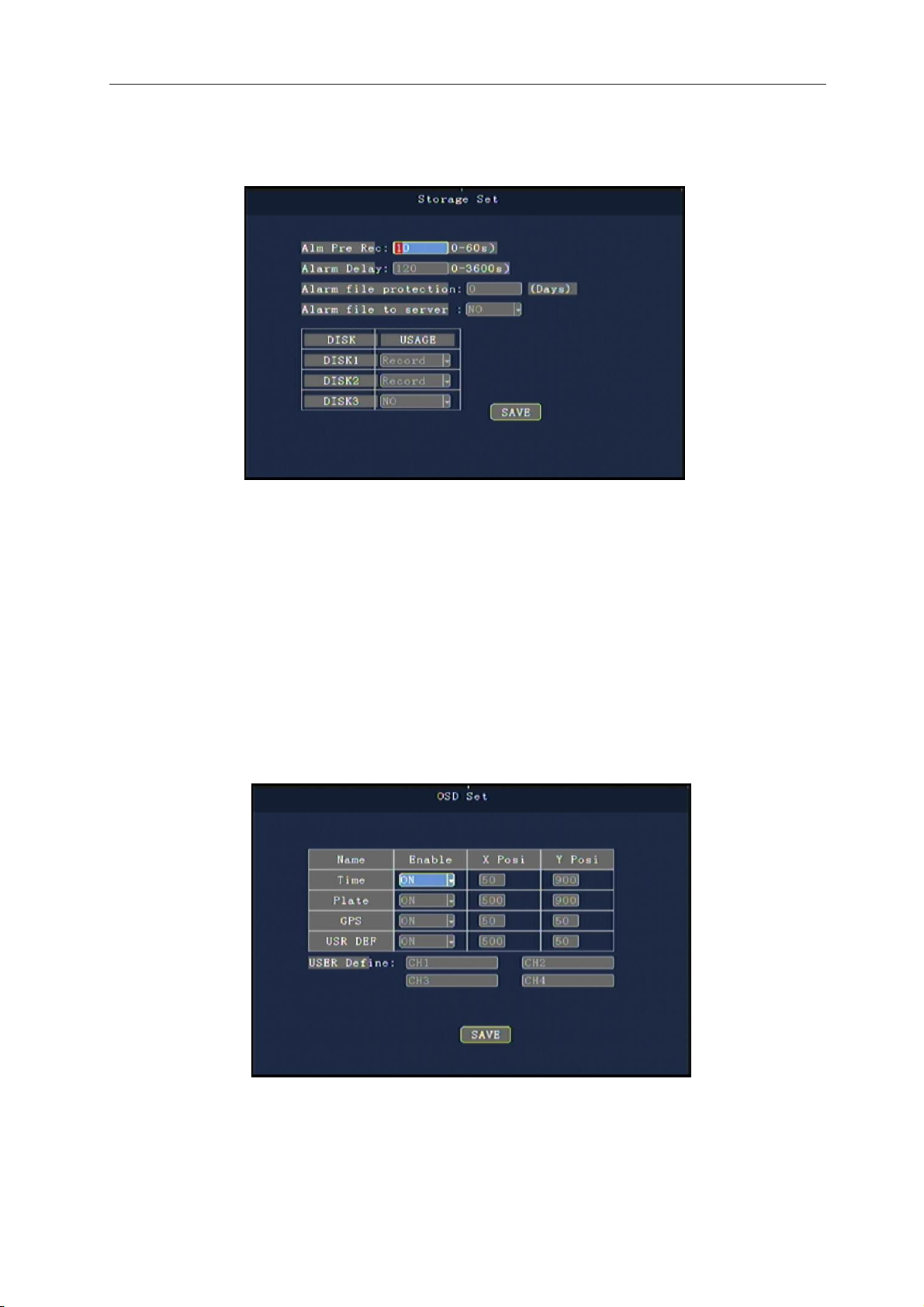
4.5.5 Storage Setting
This menu is used to set parameters for the transport sub stream
Alm Pre Rec:0-60 seconds, press Enter.
Alarm Delay:Range of 120 seconds to 3600 seconds, press Enter.
Alarm File:Alarm recording time on the SD card storage, range 3-45 days, press the
number keys to enter.
Optional storage location DISK1,DISK2,DISK3(SD1, SD2,USB).
4.5.6 OSD Setting
Time/Plate/GPS/USER DEF::::On / off, press the Enter key to select.
You can also set free superimposed coordinate that position on the screen.
24
Page 29
TK604 user manual
4.6 Network Settings (3G/4G machine support)
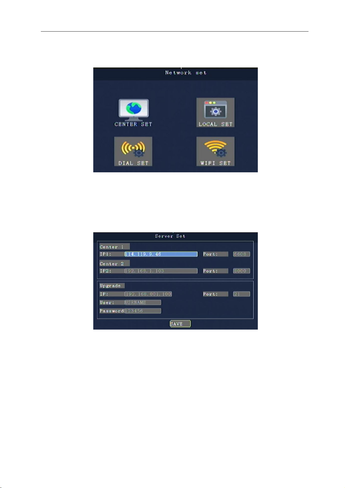
This menu includes: central setting, local network, 3G setting, WIFI setting
4.6.1 Center set up
Sets the IP and parameters of the reported central server
“Center" : set up 3G video center to monitor the IP address or domain name of the server, port information,
etc., and realize the 3G configuration of 3G video network function.
"Center IP”: sets the IP address or domain name of the 3G center monitoring center server.
Use [OK] key input, then enter the keyboard interface, enter the number by remote control, move the cursor
to select the corresponding letter and symbol input by the [OK] key.
“Port”: set up the port number of 3G devices and servers for communication. The port configuration must
be consistent with the server configuration.
25
Page 30
TK604 user manual
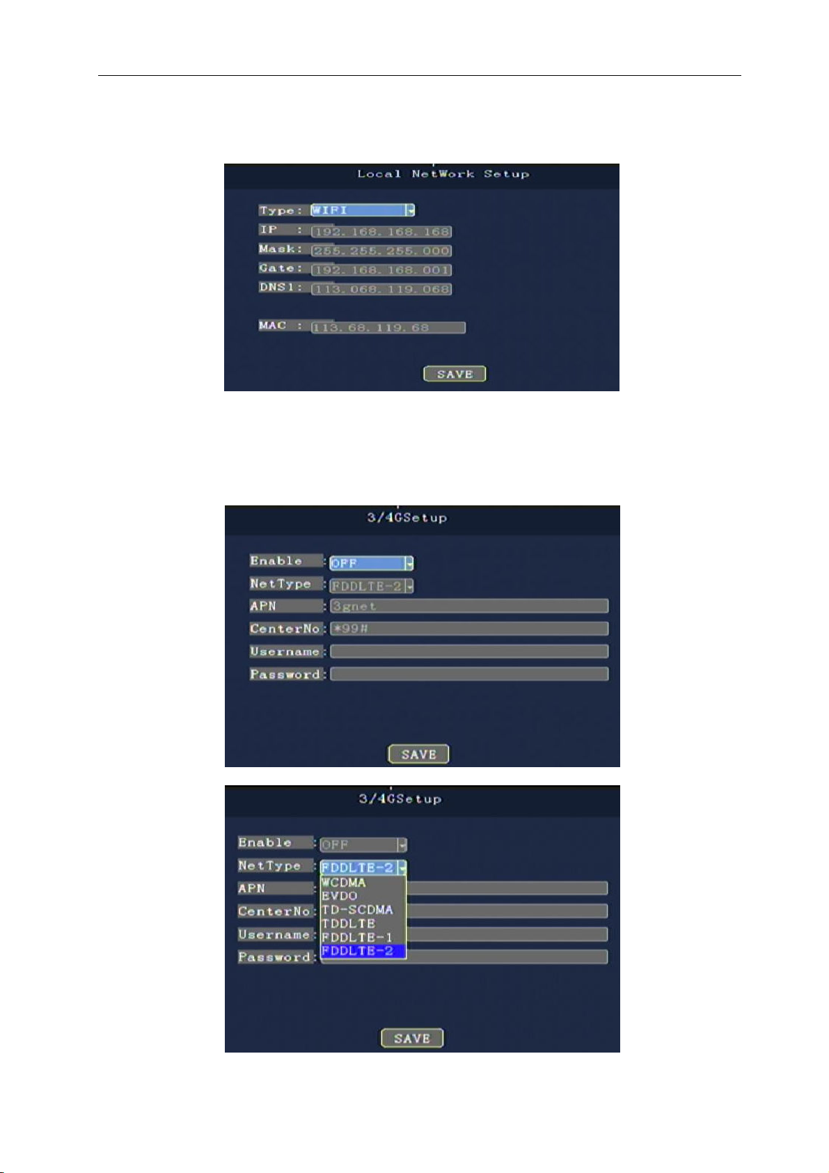
4.6.2 Local Settings
This menu is used to set local network connections
4.6.3 Dial-up Settings
This menu is used to set up configuration information for 3G/4G networks
26
Page 31
TK604 user manual
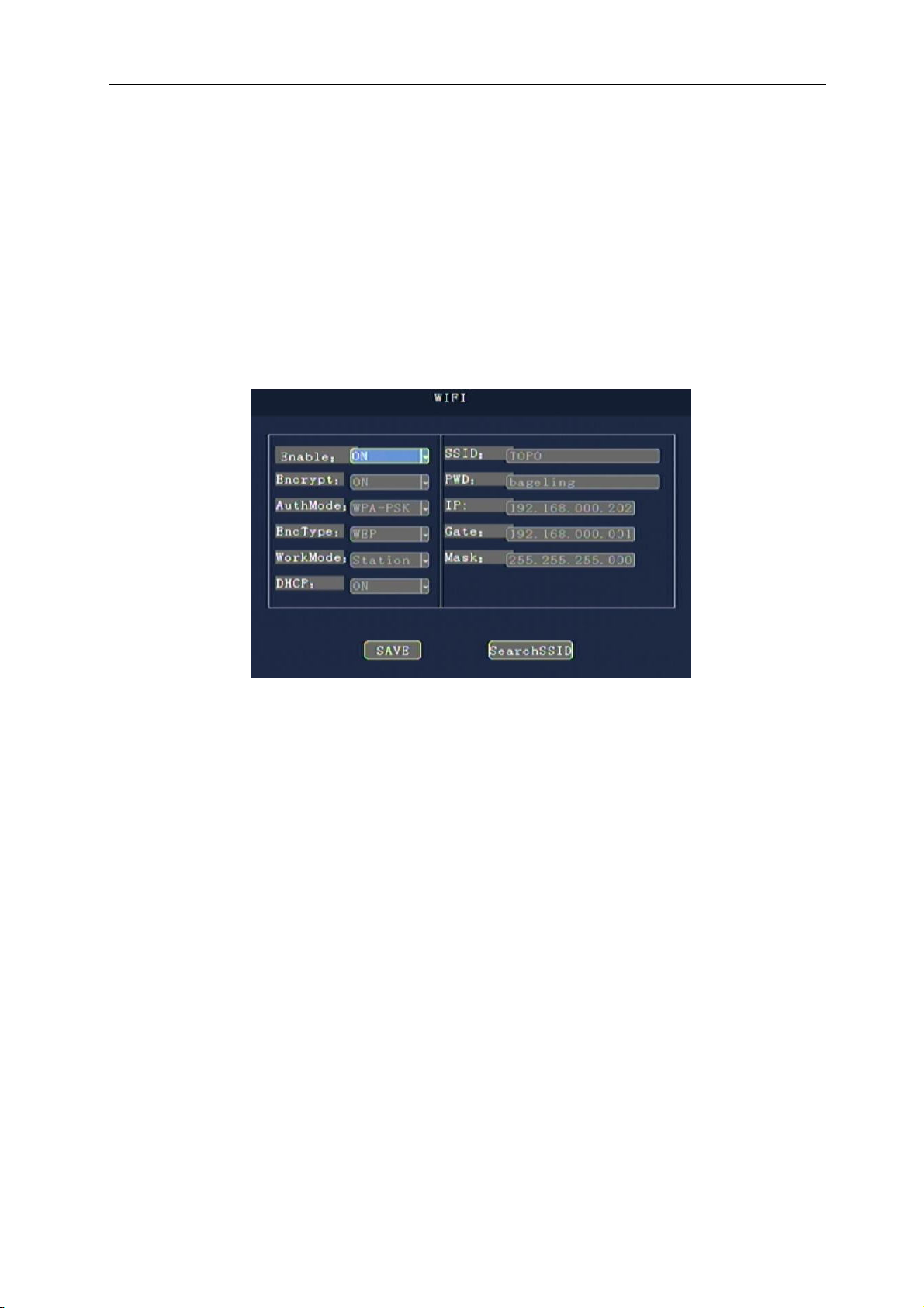
"Enable”: set up or disable the wireless communication function and press the [OK] key to enter.
"Type”: sets the type of wireless module, WCDMA, EVDO, TD-SCDMA, TD-LTE, and FDD-LTE press [OK] key
input.
"APN”: set up the data access point, type in the [OK] key, then enter the keyboard interface, and move the cursor to
select the corresponding letter input.
"User name", "password" : set the user name and password of wireless business, with the "OK" key input, then into
the keyboard interface, move the cursor press [OK] to choose the corresponding letter input.
4.6.4 WIFI Settings
"WIFI enabled”: set open or turn off WIFI function, press [OK] key input.
"Encryption enable”: Settings open or close WIFI encryption function, press [OK] key input.
"Authentication mode”: set up the authentication mode of WIFI, please select the same as WIFI router, press [OK]
key input.
"Encryption type”: to set the encryption type of WIFI, please select the same as WIFI router and press the [OK] key
to enter.
"IP", "mask" and "gateway”: set the IP address, mask and gateway of WIFI module or device
"SSID”: to set up the SSID of WIFI network, please select the same as WIFI router and press [OK] key to enter.
"Password”: set WIFI network access password, please choose to agree with WIFI router, press [OK] key input.
27
Page 32
TK604 user manual
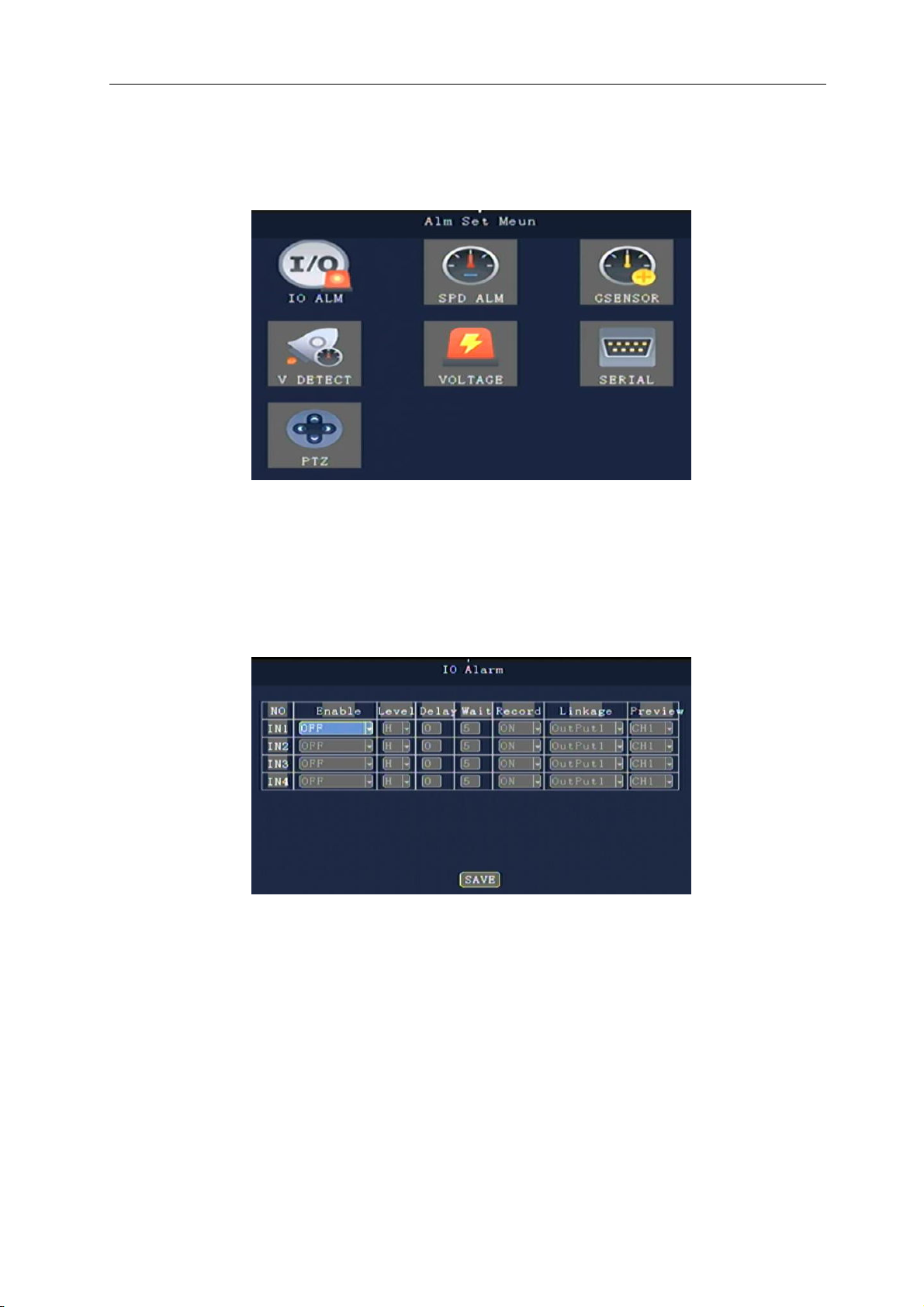
4.7 Alarm and peripherals
This menu includes IO alarm, speed alarm, acceleration, mobile detection, voltage alarm, serial port
management and PTZ.
4.7.1 IO alarm
It can set the alarm input, alarm level, delay time and linkage information
"Enable”: whether to open alarm function, and select alarm type, press [OK] key to enter the modification.
"Level”: select alarm trigger level, select high level alarm and low level alarm, press [OK] key to enter the
modification.
"Delay”: when the alarm is triggered, it is necessary to delay the alarm triggering, which can set the delay time and
reduce the false alarm. Press [OK] to enter the modification.
"Record”: alarm whether to turn on video function, press [OK] key input modification.
“Linkage”: if the alarm is connected, click the "OK" key to enter the change.
"Preview”: when the alarm is triggered, the selection of video preview can be used to reverse the video, open and
close video and other functions as the "OK" key to enter the modification.
28
Page 33
TK604 user manual
4.7.2 Speed alarm
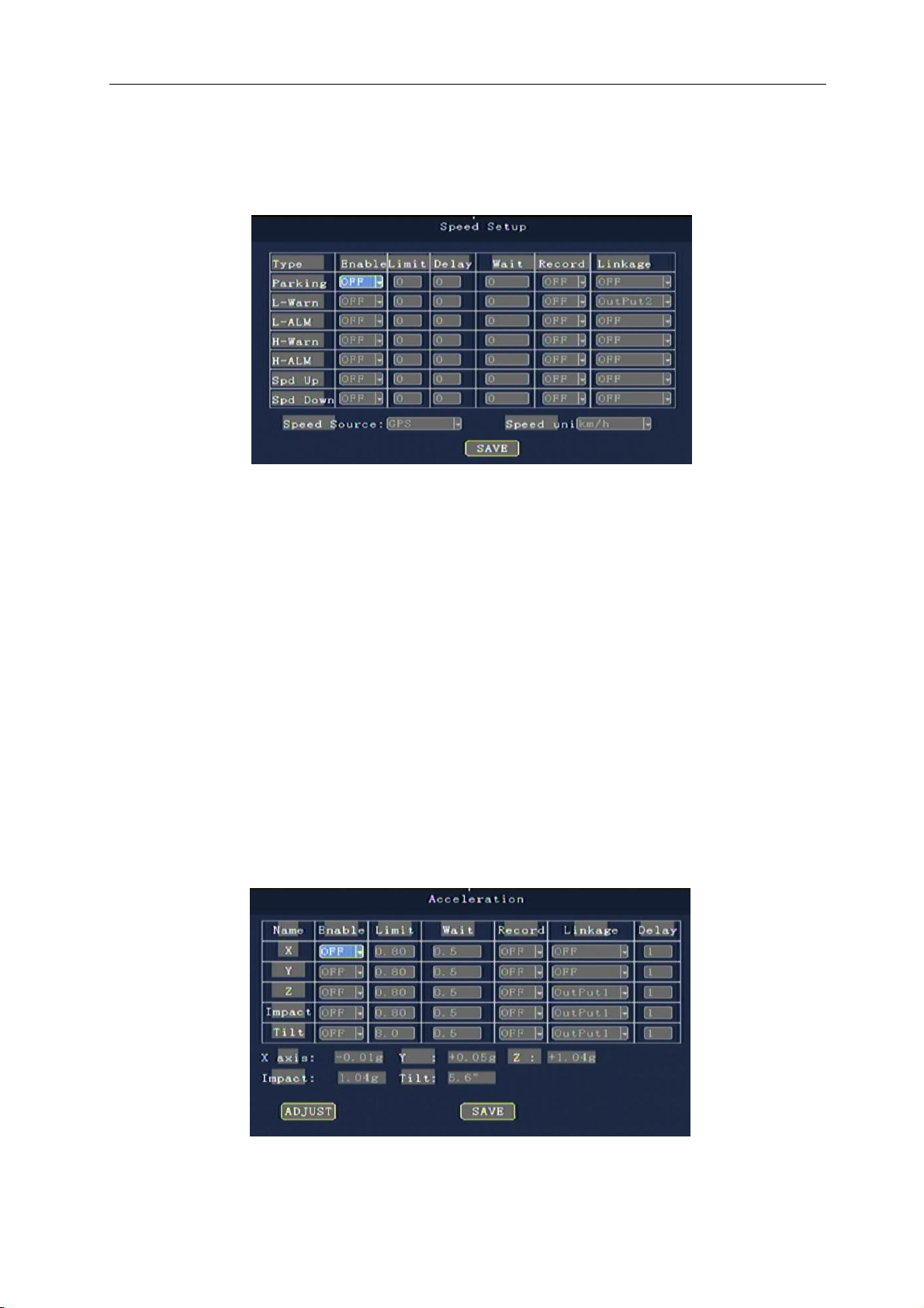
Can set the speed of the vehicle (speeding, low speed) and the alarm of illegal driving behavior
"Speed Source " : the information source of the vehicle speed can be used to select GPS and vehicle pulse signal
and input the modification according to the remote control [OK] key. "pulse" coefficient by pulse
acquisition vehicle speed signal must be set when the pulse system as a standard of testing
speed, press the number keys input change, searchable vehicle data or by a vehicle moving at a
constant speed, by numerical setting for many times in the right number.
"Speed unit”: the unit of speed use, press [OK] key to enter the modification.
Parking "timeout", "low speed alarm", "low speed warning", "high alert", "high speed alarm" : by making can open
and close, start alarm functions, gate value set alarm trigger speed and time; Duration, setting alarm duration;
Whether the video was recorded when the video was set up for alarm; Alarm linkage, set alarm when the alarm
output.
4.7.3 The acceleration
This menu sets the acceleration alarm threshold and the alarm associated with the acceleration alarm
Note: before setting, you need to calibrate the current state, and then set the threshold value of the acceleration
alarm.
29
Page 34
TK604 user manual
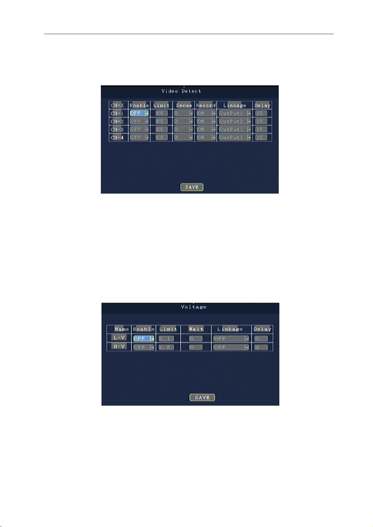
4.7.4 Video detecting
This menu sets the degree of change of image in video and related alarm linkage
"Threshold value”: sets the threshold value that triggers the motion detection
"Sensitivity”: 0-7 optional, level 0 is the lowest level, level 7 is the highest level. The default setting is level 1, the
higher the level, the lower the sensitivity and the low sensitivity will not trigger the alarm.
In order to achieve the best results, you need to set the appropriate parameters according to the actual environment.
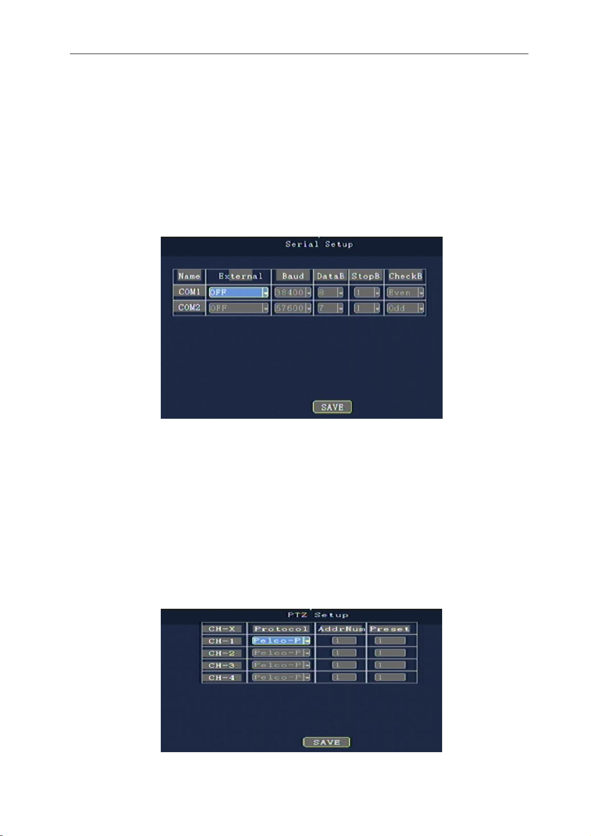
4.7.5 Voltage alarm
Set voltage alarm correlation parameters and alarm linkage
"Low voltage" means that the current input voltage is below the set voltage threshold, "above" means that the
current input voltage is above the current set voltage threshold.
"Enable”:
"
Limit”:Range alarm value. Minimum voltage and maximum voltage press Enter.
"
Wait”:Image stabilization level
30
ON/OFF, press [Enter] key to select.
Page 35
TK604 user manual
"alarm linkage”:
When the "alarm linkage" detects that the duration of the abnormal voltage exceeds the set duration, the
corresponding action of the trigger voltage is triggered.
Set the appropriate offer voltage parameters, outdated equipment when the battery voltage automatic shutdown,
can effectively protect the car battery discharge, avoid vehicles could not be started because the battery voltage is
too low, and can prolong the service life of the battery.
OFF / Output 1 /Output 2, press the [Enter] key to select.
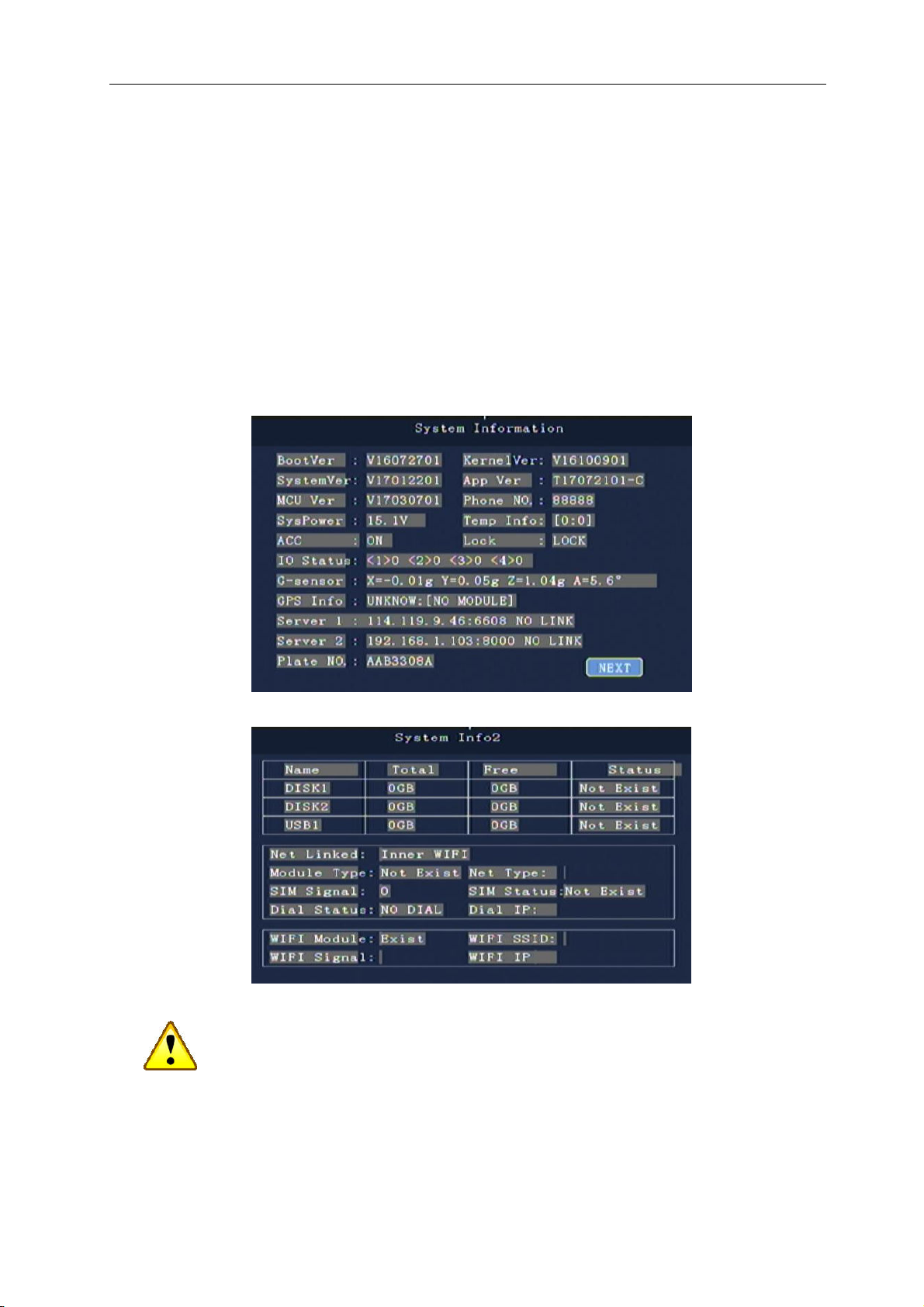
4.7.6 Serial port Settings
The serial port parameter setting of serial port extension device can be used for external LED advertisement
screen, TTS speech module, oil meter, g-sensor external SENSOR, card reader, etc
"External”: the selection of the device type of the serial port, press [OK] key to enter the modification.
"Baud rate”: select the baud rate of the serial port of the external device, and press [OK] key to enter the
modification.
"Data bits”: select the data bits of the external device serial port, and press [OK] key to enter the modification.
"Stop bit”: select the stop position of serial port of serial port, press [OK] key to enter the modification.
"Check bit”: select the test bit of the serial port of the external device, and press [OK] key to enter the modification.
4.7.7 PTZ Setup
The cloud control is used to control the parameters of the control cloud billiard machine
31
Page 36
TK604 user manual
"Protocol type”: the selection of the type of protocol supported by the ball machine, and press the [OK] key to
enter the modification.
“Address code”: select the address code of the ball machine and enter the modification according to the digital key.
"Preset position”: select the preset bit code of the ball machine and enter the modification according to the digital
key.
4.8 System information
The system information is shown in 2 pages, which shows the state of the device, disk information and
network information. In addition to menu calls, you can also use the INFO key directly in the preview screen.
Pay attention to:
Installing a number of devices and each device is set at the same time, please use the configuration of import
and export, namely setting up a device, export the configuration file, and then imported into the other devices
can be realized each device configuration is the same。。。。
32
Page 37

TK604 user manual
5 Installation of equipment
5.1 Installation Environment
The TK604 ADAPTS to a complex vehicle environment. Specific indicators are as table 1:
Table 1 list of environmental performance indicators of TK604
projects
High temperature working limit
Low temperature working limit
Relative humidity
Maximum temperature gradient
Vibration limit (non-current state)
Vibration limit (normal work)
Impact limit (non-current state)
index
+60℃
-25℃
10%~95%
20℃/小时
No more than 5mm p-p
(5-22hz)49m/s2 (5.0G)
(22-500hz)
No greater than 1.0mm
p-p (5-22hz)9.8 m/s2 (1.0
G) (22-500 hz)
Not greater than 2000G
(19,600 m/s2)(duration 1
ms, half sine wave)
example
Ventilation condition
Belt packing, transportation, handling
Installation of equipment is good. The vibration
energy in the main frequency domain of the
vehicle is generally within 0.5 Grms.
Pack, free of hard disk, transport, and drop,
equivalent to 1.5m height, fall on cement
surface
No more than 1000G,
Impact limit (normal work)
(9,800 m/s2) (duration 2
ms, half sine wave)
Install the good
5.2 Installation considerations
considerations
To ensure the safe use of TK604 and obtain satisfactory performance and extend the service life of the
equipment, please consider the following factors when installing the equipment:
1) Comply with the specifications of all electronic products and the requirements of vehicles and other connecting
equipment when installing and operating equipment.
33
::::
Page 38
TK604 user manual
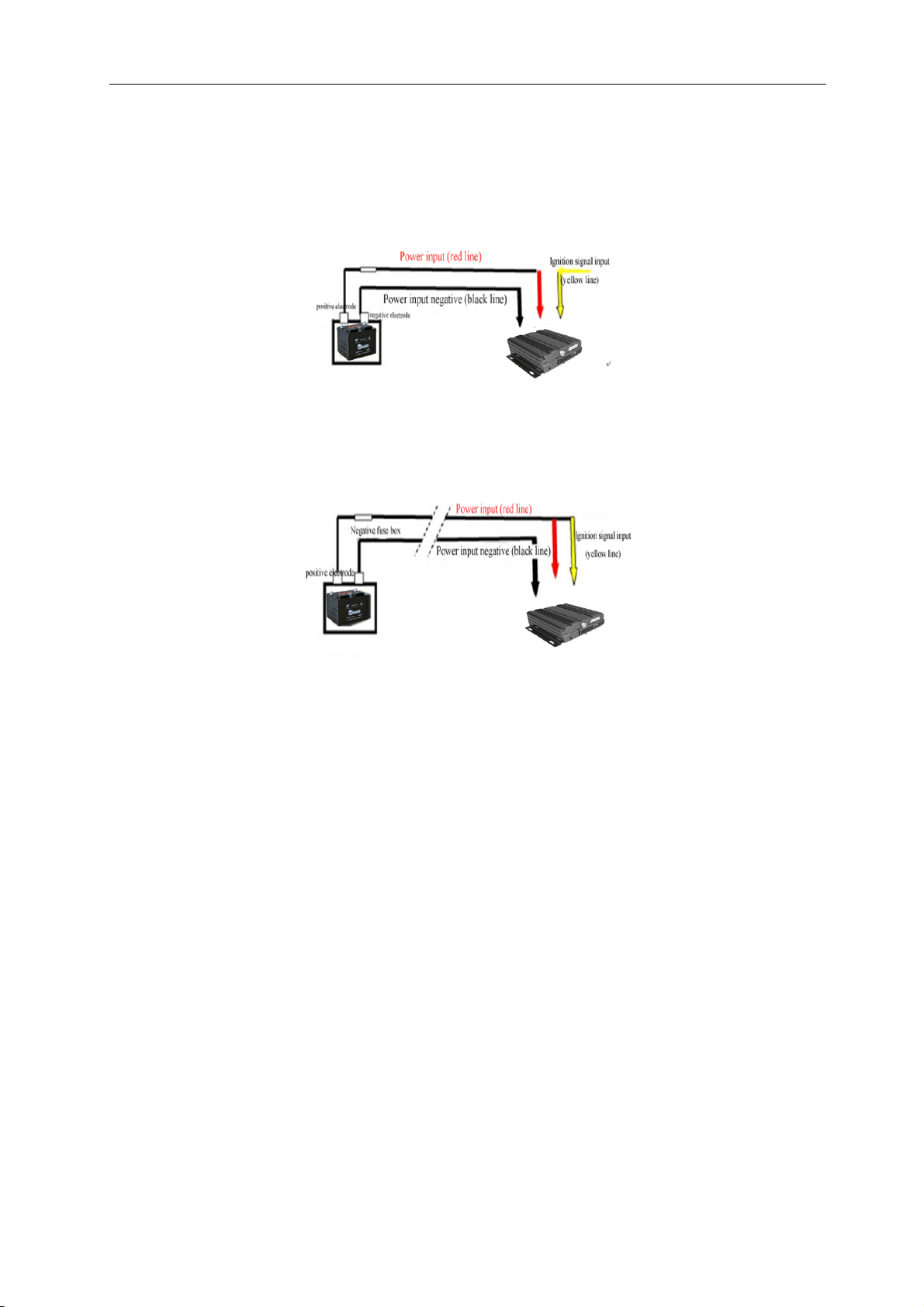
2) Power supply and grounding:
A) The MDVR USES dc power, and please pay attention to positive and negative polarity when connecting the
power supply.
Use the ignition delay control car video recorder work indicates that the figure is as follows:
The total gate connection examples (the total gate control switch video) as shown below:
B) The MDVR input voltage range is 6V ~ 36V, do not connect to the power source beyond this range. Too low
voltage will cause the MDVR to work, and excessive voltage will damage the MDVR.
C) It is recommended that the MDVR be directly connected to the battery power output. Please note; do not take the
generator power output from the car, because the generator output may produce instantaneous high voltage at
startup, damaging the MDVR.
D) when the MDVR is connected to the battery, the start-up power is over 60 W (the power consumption varies
depending on the external equipment).The power supply must be capable of providing over 60 watts of power (for
example, when the power output voltage of the car is 12V, the power cord must be able to withstand the current of
more than 5 A).
E) Even if the device is shut down, the machine is electrically charged and should avoid short circuit. Disconnect
between the device and the power supply before connecting to other external devices.
F) The external output voltage of the device is 12V, which is only used to power the camera. Do not attach any
equipment that is not allowed to be used on the device.
G) The input mode of the equipment sensor is in the mode of level. The external voltage is lower than 2V, which is
considered as low level and is in the range of 5V ~ 30V, which is considered to be high level, over 30V, which can
lead to equipment damage. When the voltage is greater than 2V less than 5V, it is illegal.
H) Properly connect the ground wire of the equipment to the circuit of the vehicle.
I) if the machine is not used for a long time, it is better to completely disconnect the equipment to extend the service
life.
J) it is recommended to wear resistance, heat resistant, waterproof, and oil - proof sleeve outside the power cord to
prevent the short circuit or break of the line due to the long vibration in the car.
34
Page 39

TK604 user manual
K) The power is close to the power output of the car, and the box must be installed with 10 ampere.In case of a short
circuit on the power line, burn the power of the car.
3) Humidity requirements:
A) In the dry environment installation equipment, avoid wet, water, water and other places.Do not install the
equipment in the place where the sag is or the wet ground where the liquid will drip.
B) Do not touch the equipment with wet hand touch, nor stand in the water or contact with other water sources.
4) Installation location:
A) To extend the life of the equipment, please install the equipment as far as possible in the weaker parts of the
vehicle, such as the rear of the driver's seat.
B) the equipment shall be installed in the ventilated parts of the vehicle: the equipment installed in the plane shall be
6 inches (15cm) away from other objects to facilitate air circulation and heat dissipation; Cannot be installed in
enclosed Spaces (e.g. car trunk).
C) The external wire of the equipment shall have sufficient intervals and jacket flame retardant protection to ensure
that the wires are not bent or the shock wears away.
D) Ensure that the equipment is far from the heat source on the vehicle, and there is no clutter around the
equipment, and no items should be placed on the equipment.
E) Equipment can only be vertical or lateral horizontal installation (if you have other direction installation
requirements, please consult factory), may damage the equipment in any other installation Angle, are forbidden.
5) Equipment safety:
A) Ensure that passengers or drivers are unable to intervene and damage equipment parts, cameras, wire and other
accessories, and do not install equipment in places close to other restricted vehicle components.
B) When installing equipment components, cameras, accessories and wires, the vehicle may cause damage to the
equipment and ensure that the vehicle is still during the installation to prevent the equipment from falling.
5.3 Open box inspection
Please check if the host has any deformation or other property damage after opening the box, please stop using it
and contact your supplier if there is any phenomenon.
5.4 Installation instructions of the main engine
5.4.1 Installation of the whole machine
The installation mode of the main engine has horizontal installation and side installation.
1. Horizontal installation: the machine is placed on the mounting surface, and the screw is fixed to the fixed hole of
the four machines to tighten the machine on the mounting surface;
2. Side installation: when the machine is not able to be installed horizontally, it can be installed on the side, such as
on the vertical wall or on the side of the bus. When the side installation is adopted, the host can only have one side
facing up, and the other three sides cannot be up, and must be installed according to the instruction icon of the rear
panel of the host.
35
Page 40
TK604 user manual
B) Power cord connection
The MDVR USES dc power input, and the normal working range of input voltage is 6V~ 36V.
5.4.2 Alarm input connection
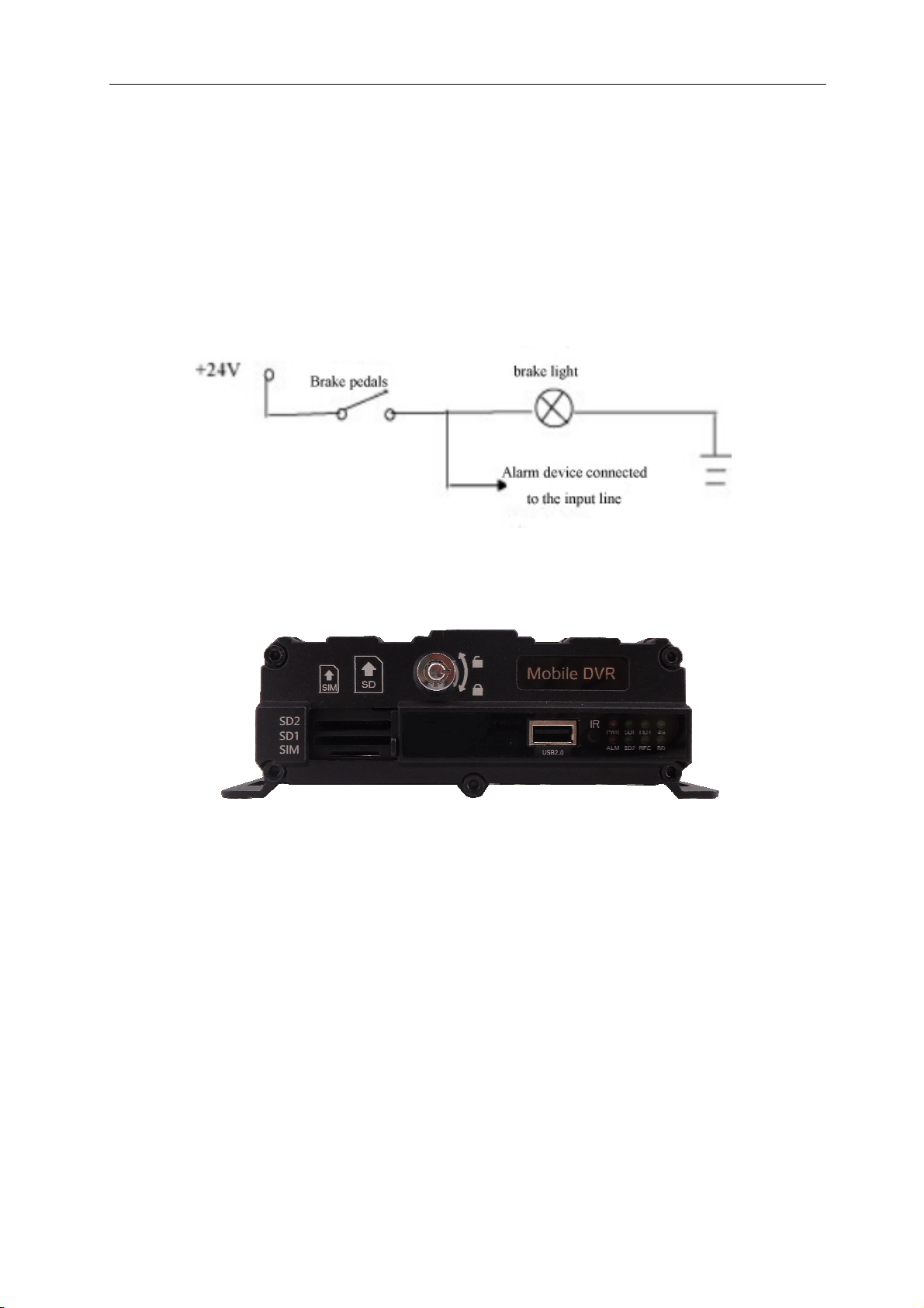
The device has 9 sets of alarm input interfaces. The detection of alarm input is a level test, which can be used
in various vehicles, such as braking, steering, etc .As shown in the diagram below, the device can detect the high
level of the brake when the brake pedal is under, otherwise it will detect a low level
a)
The alarm output is the output of the level, the driving capacity is 200MA. If the power is to drive the larger
device, the external relay must be connected.
b) SD card and SIM card installation
SD card is installed in the position of SD1 and SD2 in the figure above;
The SIM card is installed in the position of SIM in the figure above.
5.5 Equipment upgrade
A) First, COPY all the upgrade files to the SD card root. The upgrade file contains applications, file systems, and
UBOOT;
B) Insert the SD card with the upgrade file to boot;
C) Enter the system menu "system information" to view the application, files system, boot program, kernel, and
single chip version number;
D) The version number is different from the current version, which does not need to be selected in the equipment
management, and the equipment will be automatically carried out;
E) Do not use power without power during the upgrade process. Do not do any operation on the equipment.
36
 Loading...