


AR1021X-NV5
Specification
Customer:
Description:
CustomerP/N:
Date:
Customer
AR1021X-NV5
Approve Auditing Ad
Provider
Approve Auditing Ad
mit
mit
Product Specification
802.11a /n
USB AR1021X-Module
AR1021X-NV5
Version 1.0
Docume
nt
release
Version 1.0 2014-05-10 Initial release
Date
Modific
ation
Approved

CONTENTS
1. Product Overview............................................................................................................................
2. Module Hardware Overview...........................................................................................................
2.1 Block Diagram......................................................................................................................
2.2
2.3
3. Electrical Specification...................................................................................................................
3.1 Recommendedoperatingrating..........................................................................................
3.2
3.3 Environment Storage Condition.........................................................................................
4. RF Specification..............................................................................................................................
4.1 IEEE 802.11a.......................................................................................................................
4.2
4.3
5. Mechanical Specifications............................................................................................................
6. Ordering Information................................ ....................................................................................
Features............................. ....................................................................................................
Interface............................................................... .................................................................
DC Characteristics............ ............ ........ ......... ......... ........ .......... .......... ......... ......... ........ ......
IEEE 802.11n HT20(5G)..................................................................................................
IEEE 802.11n HT40(5G)..................................................................................................
1. Product Overview
The module
utilizing direct sequence spread spectrum and OFDM/CCK technology. The module supports
IEEE 802.11a/n protocol. Data rate of up to 54Mbps for 802.11a and 144.4Mbps for 802.11n
HT20,300Mbps for HT40.The module integrates all wifi functionality in a package friendly to lowcost PCB design, requiring only a external 3.3V power supply and connection to antenna.
The module is based on Qualcomm Atheros AR1021X which is highly integrated,system-on-a
-chip solution for 5GHz IEEE 802.11n 2x2 MIMO WLAN with internal PA and LNA.
AR1021XNV5
2. Module Hardware Overview
provides wireless modem functionality for CE
applications
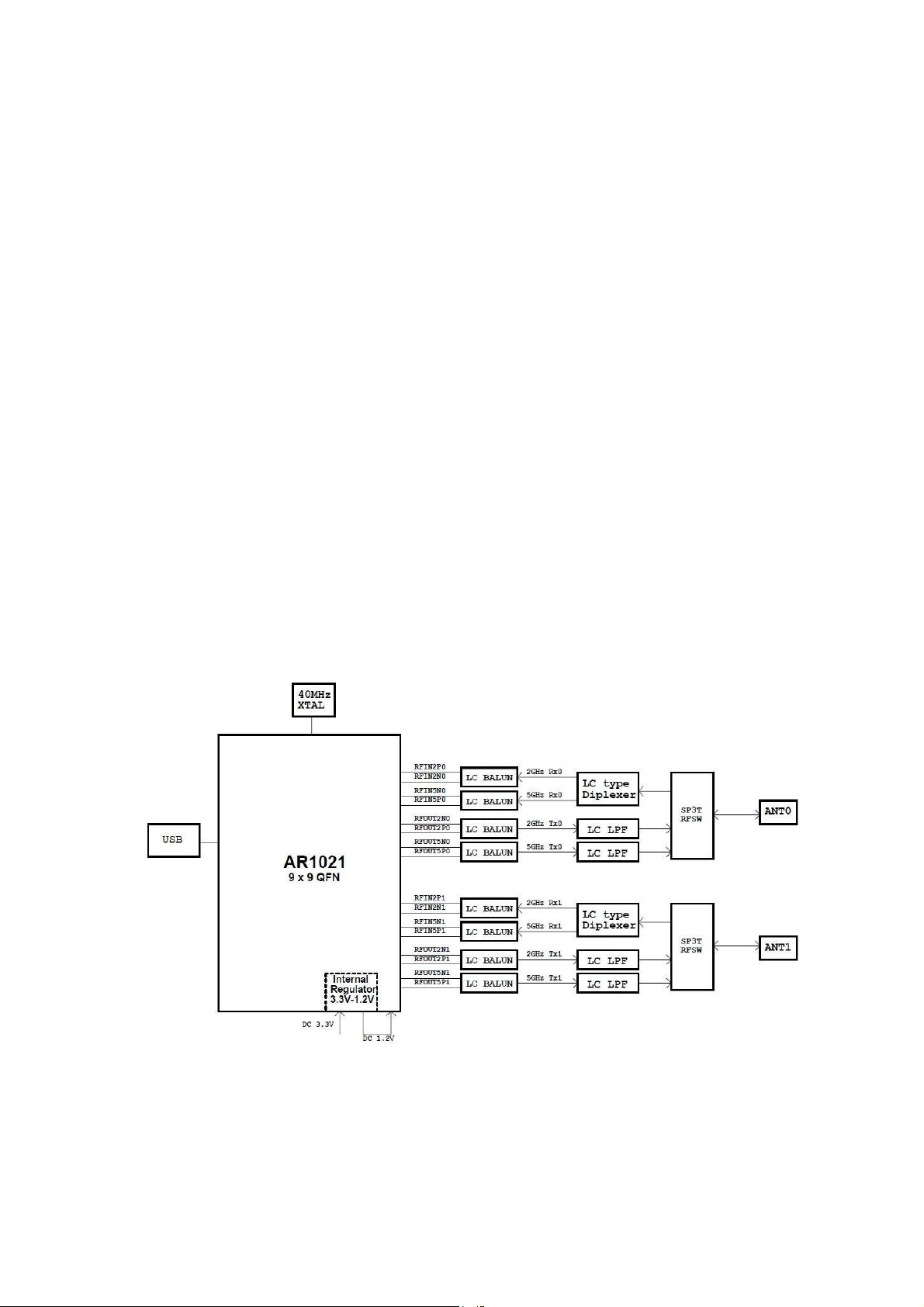
2.1 Block Diagram
The general Hardware architecture is shown below Figure:
Module Block Diagram

2.2 Features
IEEE802.11a/n (2X2) based on Qualcomm Atheros AR1021X solution
USB 2.0 Interface, High and Full Speeds supported
Module is powered by the host with a 3.3V +/- 10% supply.
Internal OTP memory for calibration data
Advanced power management to minimize standby,sleep and active power
Security support for WPS,WPA2,WPA,WAP and protected management frames
Full 802.11e QoS support including WMM and U-APSD
Support for the IEEE 802.11e,h,i,j
WEP, T K I P,an d AES hardware encryption
Support Ad hoc and infrastructure mode

2.3 Interface
Interface
Pin definition
• Interface: Half Hole
• Antenna: IPEX connector
From Module TOP View
Symbol Name Sta
1 LED O LED indication
2 GND P Ground pad
3 USB_DP I/O USB D+ signal
4 USB_DN I/O USB D- signal
5 3.3V P Analog 3.3V power supply
6 CHIP_PWD_L I Reset, low active
Blue pin--On all layer
Red pin--On the bottom side
Num
Note:
Pin
ber
tus
Pin
Description

3. Electrical Specification
3.1 Recommended operating rating
Element Sym
DC supply
voltage
UV+ 3.
3.2 DC Characteristics
Sy
mb
ol
ST
B
Y
3.
3V
Supply voltage 3.0 3.3 3.
Power Saving -- 450 -- (u
Standby -- 112 -- (m
Continuous Tx Current 5GHz(Dual Chain) -- 480 -- (m
Continuous Rx Current 5GHz(Dual Chain) -- 60 -- (m
bol
Parame
ter
M
i
n
0
T
y
p
3
.
3
Min Typ M
M
a
x
3.
6
U
ni
t
(
V
)
Un
a
x
6
it
(V
)
A)
A)
A)
A)
3.3 Environment Storage Condition
Environment
condition
Temperature
Humidity
Operating Temperature: -10 deg.C ~70 deg.C
Storage Temperature: -40 deg.C ~80 deg.C
Operating Humidity: 5% ~95% (Non-condensing)
Storage Humidity: 5% ~95% (Non-condensing)

4. RF Specification
4.1 IEEE 802.11a
Items Contents
Specification IEEE 802.11a
Modulation technique OFDM
Channel 5180 ~ 5825MHz
Data rate 6,9,12,18,24,36,48,54Mbps
TX Characteristics Mi
n.
1. Power Levels(SISO)
1)Target Power@6Mbps 14 16 18 dBm
2)Target Power@9Mbps 14 16 18 dBm
3)Target Power@12Mbps 14 16 18 dBm
4)Target Power@18Mbps 14 16 18 dBm
5)Target Power@24Mbps 14 16 18 dBm
6)Target Power@36Mbps 12 14 16 dBm
7)Target Power@48Mbps 10 12 14 dBm
8)Target Power@54Mbps 9 11 13 dBm
2. Spectrum Mask@Target Power
1) at fc ± 11MHz - - -20 dBr
2) at fc ± 20MHz - - -28 dBr
3) at fc > ± 30MHz - - -40 dBr
3. Frequence Error -20 - +2
4. Modulation Accuracy(EVM)@Target Power
1) 6Mbps -
2) 9Mbps -
3) 12Mbps -
4) 18Mbps -
5) 24Mbps -
6) 36Mbps -
7) 48Mbps -
8) 54Mbps - -30 -25 dB
RX Characteristics Mi
5. Minimum Input Level Sensitivity
1) 6Mbps(PER < 10%) - -94 -90 dBm
2) 9Mbps(PER < 10%) - -93 -89 dBm
3) 12Mbps(PER < 10%) - -92 -88 dBm
4) 18Mbps(PER < 10%) - -89 -85 dBm
5) 24Mbps(PER < 10%) - -86 -82 dBm
6) 36Mbps(PER < 10%) - -82 -78 dBm
7) 48Mbps(PER < 10%) - -78 -74 dBm
8) 54Mbps(PER < 10%) - -77 -71 dBm
6. Maximum Input Level (PER < 10%) -30 - - dBm
n.
Typ. Ma
Typ. Ma
Unit
x.
ppm
0
-5 dB
-8 dB
-10 dB
-13 dB
-16 dB
-19 dB
-22 dB
Unit
x.
4.2 IEEE 802.11n HT20(5G)
Item
s
Specification IEEE 802.11a/n HT20
Modulation technique OFDM
Channel 5180 ~ 5825MHz
Data rate MCS0 ~ MCS15
TX Characteristics Mi
n.
1. Power Levels
1)Target Power@MCS0 14 16 18 dBm
2)Target Power@MCS1 13 15 17 dBm
3)Target Power@MCS2 13 15 17 dBm
4)Target Power@MCS3 13 15 17 dBm
5)Target Power@MCS4 12 14 16 dBm
6)Target Power@MCS5 11 13 15 dBm
7)Target Power@MCS6 10 12 14 dBm
8)Target Power@MCS7 8 10 12 dBm
2. Spectrum Mask@14dBm
1) at fc ± 11MHz - - -20 dBr
2) at fc ± 20MHz - - -28 dBr
3) at fc > ± 30MHz - - -45 dBr
3. Frequence Error -20 - +2
4. Modulation Accuracy(EVM)@Target Power
1) MCS0 -
2) MCS1 -
3) MCS2 -
4) MCS3 -
5) MCS4 -
6) MCS5 -
7) MCS6 -
8) MCS7 - -30 -28 dB
RX Characteristics Mi
5. Minimum Input Level Sensitivity
1) MCS0(PER < 10%) - -93 -89 dBm
2) MCS1(PER < 10%) - -91 -87 dBm
3) MCS2(PER < 10%) - -88 -84 dBm
4) MCS3(PER < 10%) - -83 -79 dBm
5) MCS4(PER < 10%) - -80 -76 dBm
6) MCS5(PER < 10%) - -76 -72 dBm
7) MCS6(PER < 10%) - -75 -70 dBm
8) MCS7(PER < 10%) - -73 -67 dBm
6. Maximum Input Level (PER < 10%) -30 - - dBm
n.
Contents
Typ. Ma
x.
-5 dB
-10 dB
-13 dB
-16 dB
-19 dB
-22 dB
-25 dB
Typ. Ma
x.
Unit
ppm
0
Unit
4.3 IEEE 802.11n HT40(5G)
Item
s
Specification IEEE 802.11a/n HT40
Modulation technique OFDM
Channel 5190 ~ 5815MHz
Data rate MCS0 ~ MCS15
TX Characteristics Mi
n.
1. Power Levels
1)Target Power@MCS0 12 14 16 dBm
2)Target Power@MCS1 11 13 15 dBm
3)Target Power@MCS2 11 13 15 dBm
4)Target Power@MCS3 11 13 15 dBm
5)Target Power@MCS4 11 13 15 dBm
6)Target Power@MCS5 10 12 14 dBm
7)Target Power@MCS6 9 11 13 dBm
8)Target Power@MCS7 7 9 11 dBm
2. Spectrum Mask@14dBm
1) at fc ± 11MHz - - -20 dBr
2) at fc ± 20MHz - - -28 dBr
3) at fc > ± 30MHz - - -45 dBr
3. Frequence Error -20 - +2
4. Modulation Accuracy(EVM)@Target Power
1) MCS0 -
2) MCS1 -
3) MCS2 -
4) MCS3 -
5) MCS4 -
6) MCS5 -
7) MCS6 -
8) MCS7 - -31 -28 dB
RX Characteristics Mi
5. Minimum Input Level Sensitivity
1) MCS0(PER < 10%) - -89 -85 dBm
2) MCS1(PER < 10%) - -87 -83 dBm
3) MCS2(PER < 10%) - -84 -80 dBm
4) MCS3(PER < 10%) - -80 -76 dBm
5) MCS4(PER < 10%) - -77 -73 dBm
6) MCS5(PER < 10%) - -73 -69 dBm
7) MCS6(PER < 10%) - -71 -67 dBm
8) MCS7(PER < 10%) - -70 -64 dBm
6. Maximum Input Level (PER < 10%) -30 - - dBm
n.
Contents
Typ. Ma
x.
0
-5 dB
-10 dB
-13 dB
-16 dB
-19 dB
-22 dB
-25 dB
Typ. Ma
x.
Unit
ppm
Unit
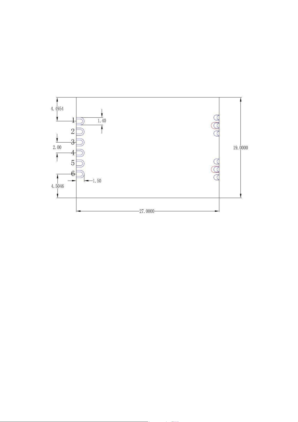
5.Mechanical Specifications
PCB Assembly Dimension:
Dimension (L x W x H): L:19.0mm* W:27.0mm * H:2.3 mm
Solder joints used by the module is connected to the terminal device.
Size of connection position is shown in the figure below:
te: 5180-5240MHz can only be used indoors
No

FCC WARNING
This device complies with part 15 of the FCC Rules. Operation is subject to the following two conditions:
(1) this device may not cause harmful interference, and (2) this device must accept
any interference received, including interference that may cause undesired operation.
Any changes or modifications not expressly approved by the party responsible for compliance
could void the user's authority to operate the equipment.
NOTE: This equipment has been tested and found to comply with the limits for a Class B
digital device, pursuant to Part 15 of the FCC Rules. These limits are designed to provide
reasonable protection against harmful interference in a residential installation. This equipment generates,
uses and can radiate radio frequency energy and, if not installed and used in
accordance with the instructions, may cause harmful interference to radio communications.
However, there is no guarantee that interference will not occur in a particular installation.
If this equipment does cause harmful interference to radio or television reception,
which can be determined by turning the equipment off and on, the user is encouraged to try to
correct the interference by one or more of the following measures:
-- Reorient or relocate the receiving antenna.
-- Increase the separation between the equipment and receiver.
-- Connect the equipment into an outlet on a circuit different
from that to which the receiver is connected.
-- Consult the dealer or an experienced radio/TV technician for help.
This equipment complies with FCC radiation exposure limits set forth for an uncontrolled environment.
This equipment should be installed and operated with minimum distance 20cm between the radiator
and your body.
This module meets the requirements of FCC part 15C(15.407).it specifically establish the Bandwidth,
Output Power, Radiated Spurious Emission, Power Spectral Density, Restricted Band of Operation and
Band Edge, Out of Band Emissions. It is U.FL connect to the antenna, antenna gain 3dBi, antenna gain
tolerance:0.5dB
The antenna cannot be removed , Unconventional interface, The module with trace antenna designs, and
This manual has been shown the layout of trace design, antenna, connectors, and isolation requirements.
This module It’s complies with FCC RF radiation exposure limits set forth for an uncontrolled environment.
This module is designed to comply with the FCC
statement, FCC ID is: ZLJTOP-AR1021.
The host system using this module, should have label in a visible area indicated the following texts:
"Contains FCC ID: ZLJTOP-AR1021.
TOPLINKST TECHNOLOGY COMPANY LIMITED can increase the utility of our modular transmitters by
providing instructions that simulates or characterizes a connection by enabling a transmitter.
The module without unintentional-radiator digital circuity, so the module does not require an evaluation
by FCC Part 15 Subpart B. The host shoule be evaluated by the FCC Subpart B.
 Loading...