


Product Specification
802.11 a/b/g/n
USB AR1021X-Module
Document
release
Date
Modification
Approved
Version 1.0
2014-05-10
Initial release
AR1021X-NV5
Version 1.0

CONTENTS
1. Product Overview............................................................................................................................
2. Module Hardware Overview...........................................................................................................
2.1 Block Diagram......................................................................................................................
2.2 Features.................................................................................................................................
2.3 Interface................................................................................................................................
3. Electrical Specification...................................................................................................................
3.1 Recommendedoperatingrating..........................................................................................
3.2 DC Characteristics..............................................................................................................
3.3 EnvironmentStorageCondition.........................................................................................
4. RF Specification..............................................................................................................................
4.1 IEEE802.11b......................................................................................................................
4.2 IEEE802.11g......................................................................................................................
4.3 IEEE802.11n HT20(2.4G).................................................................................................
4.4 IEEE802.11n HT40(2.4G).................................................................................................
4.5 IEEE802.11a.......................................................................................................................
4.6 IEEE802.11n HT20(5G)..................................................................................................
4.7 IEEE802.11n HT40(5G)..................................................................................................
5. Mechanical Specifications............................................................................................................
6. Ordering Information....................................................................................................................
1.
Product Overview
The module
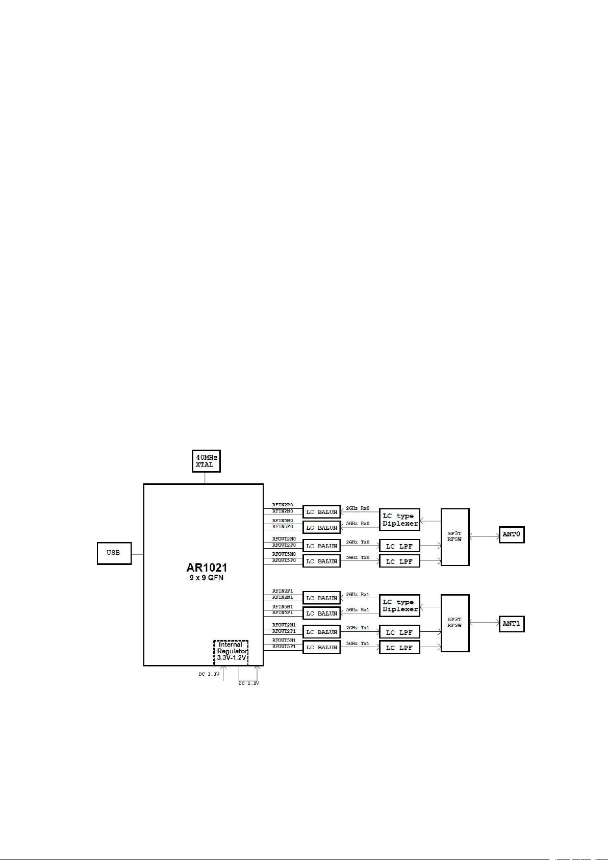
The module is based on Qualcomm Atheros AR1021X which is highly integrated,system-on-a
2.
Module Hardware Overview
2.1
Block Diagram
utilizing direct sequence spread spectrum and OFDM/CCK technology. The module supports
IEEE 802.11a/b/g/n protocol. Data rate of up to 54Mbps for 802.11a/g and 144.4Mbps for 802.11n
HT20,300Mbps for HT40.The module integrates all wifi functionality in a package friendly to
low-cost PCB design, requiring only a external 3.3V power supply and connection to antenna.
-chip solution for 2.4/5GHz IEEE 802.11n 2x2 MIMO WLAN with internal PA and LNA.
The general Hardware architecture is shown below Figure:
AR1021XNV5
provides wireless modem functionality for CE
applications
Module Block Diagram

2.2
Features
IEEE802.11a/ b/g/n (2X2) based on Qualcomm Atheros AR1021X solution
USB 2.0 Interface, High and Full Speeds supported
Module is powered by the host with a 3.3V +/- 10% supply.
Internal OTP memory for calibration data
Advanced power management to minimize standby,sleep and active power
Security support for WPS,WPA2,WPA,WAP and protected management frames
Full 802.11e QoS support including WMM and U-APSD
Support for the IEEE 802.11e,h,i,j
WEP,TKIP,and AES hardware encryption
Support Ad hoc and infrastructure mode
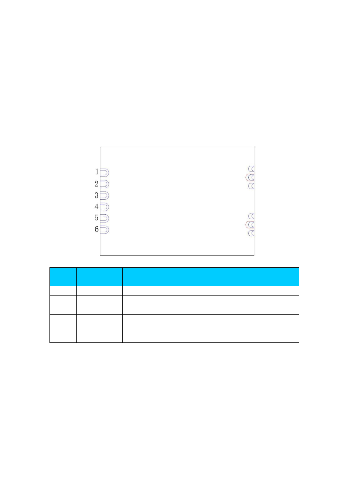
2.3
Interface
Interface
Interface: Half Hole
Antenna: IPEX connector
Pin definition
Pin
Number
Symbol Name
Status
Pin Description
1
LEDOLED indication
2
GNDPGround pad
3
USB_DP
I/O
USB D+ signal
4
USB_DN
I/O
USB D- signal
5
3.3VPAnalog 3.3V power supply
6
CHIP_PWD_L
I
Reset, low active
Note:
Blue pin--On all layer
Red pin--On the bottom side
From Module TOP View

3.
Electrical Specification
3.1
Recommended operating rating
Element
Symbol
Min
Typ
Max
Unit
DC supply voltage
UV+
3.0
3.3
3.6
(V)
3.2
DC Characteristics
Symb
ol
Parameter
Min
Typ
Max
Unit
STBY
3.3V
Supply voltage
3.0
3.3
3.6
(V)
Power Saving
--
450--(uA)
Standby
--
112--(mA)
Continuous Tx Current 2.4GHz(Dual Chain)
--
310--(mA)
Continuous Rx Current 2.4GHz(Dual Chain)
--56--
(mA)
Continuous Tx Current 5GHz(Dual Chain)
--
480--(mA)
Continuous Rx Current 5GHz(Dual Chain)
--60--
(mA)
3.3
Environment Storage Condition
Environment condition
Temperature
Operating Temperature: -10 deg.C ~70 deg.C
Storage Temperature: -40 deg.C ~80 deg.C
Humidity
Operating Humidity: 5% ~95% (Non-condensing)
Storage Humidity: 5% ~95% (Non-condensing)

4.
RF Specification
4.1 IEEE 802.11b
Items
Contents
Specification
IEEE 802.11b
Modulation technique
DSSS/CCK
Channel
CH1 ~ CH13
Data rate
1,2,5.5,11Mbps
TX Characteristics
Min.
Typ.
Max.
Unit
1. Power Levels(SISO)
1)Target Power@1Mbps
151719
dBm
2)Target Power@2Mbps
151719
dBm
3)Target Power@5.5Mbps
151719
dBm
4)Target Power@11Mbps
151719
dBm
2. Spectrum Mask@Target Power
1) fc-33MHz < f < fc-22MHz
---50
dBr
2) fc-22MHz < f < fc-11MHz
---30
dBr
3) fc+11MHz<f<fc+22MHz
---30
dBr
4) fc+22MHz<f<fc+33MHz
---50
dBr
3. Frequence Error
-20-+20
ppm
4. Modulation Accuracy(EVM)@Target Power
1) 1Mbps
-
-10
dB
2) 2Mbps
-
-10
dB
3) 5.5Mbps
-
-10
dB
4) 11Mbps
-
-10
dB
RX Characteristics
Min.
Typ.
Max.
Unit
5. Minimum Input Level Sensitivity
1) 1Mbps(PER ≤ 8%)
-
-97
-94
dBm
2) 2Mbps(PER ≤ 8%)
-
-94
-90
dBm
3) 5.5Mbps(PER ≤ 8%)
-
-92
-89
dBm
4) 11Mbps(PER ≤ 8%)
-
-90
-87
dBm
6. Maximum Input Level (PER ≤ 8%)
-10--
dBm

4.2
Items
Contents
Specification
IEEE 802.11g
Modulation technique
OFDM
Channel
Data rate
6,9,12,18,24,36,48,54Mbps
TX Characteristics
Min.
Typ.
Max.
Unit
1. Power Levels(SISO)
1)Target Power@6Mbps
151719
dBm
2)Target Power@9Mbps
151719
dBm
3)Target Power@12Mbps
151719
dBm
4)Target Power@18Mbps
151719
dBm
5)Target Power@24Mbps
151719
dBm
6)Target Power@36Mbps
141618
dBm
7)Target Power@48Mbps
131517
dBm
8)Target Power@54Mbps
121416
dBm
2. Spectrum Mask@Target Power
1) at fc ± 11MHz
---20
dBr
2) at fc ± 20MHz
---28
dBr
3) at fc > ± 30MHz
---40
dBr
3. Frequence Error
-20-+20
ppm
4. Modulation Accuracy(EVM)@Target Power
1) 6Mbps
--5dB
2) 9Mbps
--8dB
3) 12Mbps
-
-10
dB
4) 18Mbps
-
-13
dB
5) 24Mbps
-
-16
dB
6) 36Mbps
-
-19
dB
7) 48Mbps
-
-22
dB
8) 54Mbps
-
-33
-25
dB
RX Characteristics
Min.
Typ.
Max.
Unit
5. Minimum Input Level Sensitivity
1) 6Mbps(PER < 10%)
-
-94
-90
dBm
2) 9Mbps(PER < 10%)
-
-93
-89
dBm
3) 12Mbps(PER < 10%)
-
-92
-88
dBm
4) 18Mbps(PER < 10%)
-
-90
-86
dBm
5) 24Mbps(PER < 10%)
-
-86
-82
dBm
6) 36Mbps(PER < 10%)
-
-83
-79
dBm
7) 48Mbps(PER < 10%)
-
-78
-75
dBm
8) 54Mbps(PER < 10%)
-
-75
-72
dBm
6. Maximum Input Level (PER < 10%)
-20--
dBm
IEEE 802.11g
CH1 ~ CH1

4.3
Items
Contents
Specification
IEEE 802.11n HT20
Modulation technique
OFDM
Channel
Data rate
MCS0 ~ MCS15
TX Characteristics
Min.
Typ.
Max.
Unit
1. Power Levels
1)Target Power@MCS0
15
dBm
2)Target Power@MCS1
15
dBm
3)Target Power@MCS2
15
dBm
4)Target Power@MCS3
15
dBm
5)Target Power@MCS4
14
dBm
6)Target Power@MCS5
13
dBm
7)Target Power@MCS6
12
dBm
8)Target Power@MCS7
11
dBm
2. Spectrum Mask@14dBm
1) at fc ± 11MHz
---20
dBr
2) at fc ± 20MHz
---28
dBr
3) at fc > ± 30MHz
---45
dBr
3. Frequence Error
-20-+20
ppm
4. Modulation Accuracy(EVM)@Target Power
1) MCS0
--5dB
2) MCS1
-
-10
dB
3) MCS2
-
-13
dB
4) MCS3
-
-16
dB
5) MCS4
-
-19
dB
6) MCS5
-
-22
dB
7) MCS6
-
-25
dB
8) MCS7
-
-31
-28
dB
RX Characteristics
Min.
Typ.
Max.
Unit
5. Minimum Input Level Sensitivity
1) MCS0(PER < 10%)
-
-94
-90
dBm
2) MCS1(PER < 10%)
-
-91
-87
dBm
3) MCS2(PER < 10%)
-
-89
-85
dBm
4) MCS3(PER < 10%)
-
-85
-82
dBm
5) MCS4(PER < 10%)
-
-81
-77
dBm
6) MCS5(PER < 10%)
-
-77
-73
dBm
7) MCS6(PER < 10%)
-
-75
-70
dBm
8) MCS7(PER < 10%)
-
-73
-67
dBm
6. Maximum Input Level (PER < 10%)
-20--
dBm
IEEE 802.11n HT20(2.4G)
CH1 ~ CH1
19 23
19 23
19 23
19 23
17 20
16 19
15 18
13 16

4.4
Items
Contents
Specification
IEEE 802.11n HT40
Modulation technique
OFDM
Channel
Data rate
MCS0 ~ MCS15
TX Characteristics
Min.
Typ.
Max.
Unit
1. Power Levels
1)Target Power@MCS0
14
dBm
2)Target Power@MCS1
14
dBm
3)Target Power@MCS2
14
dBm
4)Target Power@MCS3
14
dBm
5)Target Power@MCS4
13
dBm
6)Target Power@MCS5
12
dBm
7)Target Power@MCS6
11
dBm
8)Target Power@MCS7
10
dBm
2. Spectrum Mask@14dBm
1) at fc ± 11MHz
---20
dBr
2) at fc ± 20MHz
---28
dBr
3) at fc > ± 30MHz
---45
dBr
3. Frequence Error
-20-+20
ppm
4. Modulation Accuracy(EVM)@Target Power
1) MCS0
--5dB
2) MCS1
-
-10
dB
3) MCS2
-
-13
dB
4) MCS3
-
-16
dB
5) MCS4
-
-19
dB
6) MCS5
-
-22
dB
7) MCS6
-
-25
dB
8) MCS7
-
-32
-28
dB
RX Characteristics
Min.
Typ.
Max.
Unit
5. Minimum Input Level Sensitivity
1) MCS0(PER < 10%)
-
-91
-87
dBm
2) MCS1(PER < 10%)
-
-88
-84
dBm
3) MCS2(PER < 10%)
-
-86
-82
dBm
4) MCS3(PER < 10%)
-
-82
-79
dBm
5) MCS4(PER < 10%)
-
-79
-74
dBm
6) MCS5(PER < 10%)
-
-74
-70
dBm
7) MCS6(PER < 10%)
-
-72
-69
dBm
8) MCS7(PER < 10%)
-
-70
-65
dBm
6. Maximum Input Level (PER < 10%)
-20--
dBm
IEEE 802.11n HT40(2.4G)
CH3 ~ CH
18 22
18 22
18 22
18 22
16 19
15 18
14 17
13 16

4.5
Items
Contents
Specification
IEEE 802.11a
Modulation technique
OFDM
Channel
Data rate
6,9,12,18,24,36,48,54Mbps
TX Characteristics
Min.
Typ.
Max.
Unit
1. Power Levels(SISO)
1)Target Power@6Mbps
141618
dBm
2)Target Power@9Mbps
141618
dBm
3)Target Power@12Mbps
141618
dBm
4)Target Power@18Mbps
141618
dBm
5)Target Power@24Mbps
141618
dBm
6)Target Power@36Mbps
121416
dBm
7)Target Power@48Mbps
101214
dBm
8)Target Power@54Mbps
91113
dBm
2. Spectrum Mask@Target Power
1) at fc ± 11MHz
---20
dBr
2) at fc ± 20MHz
---28
dBr
3) at fc > ± 30MHz
---40
dBr
3. Frequence Error
-20-+20
ppm
4. Modulation Accuracy(EVM)@Target Power
1) 6Mbps
--5dB
2) 9Mbps
--8dB
3) 12Mbps
-
-10
dB
4) 18Mbps
-
-13
dB
5) 24Mbps
-
-16
dB
6) 36Mbps
-
-19
dB
7) 48Mbps
-
-22
dB
8) 54Mbps
-
-30
-25
dB
RX Characteristics
Min.
Typ.
Max.
Unit
5. Minimum Input Level Sensitivity
1) 6Mbps(PER < 10%)
-
-94
-90
dBm
2) 9Mbps(PER < 10%)
-
-93
-89
dBm
3) 12Mbps(PER < 10%)
-
-92
-88
dBm
4) 18Mbps(PER < 10%)
-
-89
-85
dBm
5) 24Mbps(PER < 10%)
-
-86
-82
dBm
6) 36Mbps(PER < 10%)
-
-82
-78
dBm
7) 48Mbps(PER < 10%)
-
-78
-74
dBm
8) 54Mbps(PER < 10%)
-
-77
-71
dBm
6. Maximum Input Level (PER < 10%)
-30--
dBm
IEEE 802.11a
5180 5MHz0+]

4.6
Items
Contents
Specification
IEEE 802.11a/n HT20
Modulation technique
OFDM
Channel
Data rate
MCS0 ~ MCS15
TX Characteristics
Min.
Typ.
Max.
Unit
1. Power Levels
1)Target Power@MCS0
14
dBm
2)Target Power@MCS1
13
dBm
3)Target Power@MCS2
13
dBm
4)Target Power@MCS3
13
dBm
5)Target Power@MCS4
12
dBm
6)Target Power@MCS5
11
dBm
7)Target Power@MCS6
10
dBm
8)Target Power@MCS7
8
dBm
2. Spectrum Mask@14dBm
1) at fc ± 11MHz
---20
dBr
2) at fc ± 20MHz
---28
dBr
3) at fc > ± 30MHz
---45
dBr
3. Frequence Error
-20-+20
ppm
4. Modulation Accuracy(EVM)@Target Power
1) MCS0
--5dB
2) MCS1
-
-10
dB
3) MCS2
-
-13
dB
4) MCS3
-
-16
dB
5) MCS4
-
-19
dB
6) MCS5
-
-22
dB
7) MCS6
-
-25
dB
8) MCS7
-
-30
-28
dB
RX Characteristics
Min.
Typ.
Max.
Unit
5. Minimum Input Level Sensitivity
1) MCS0(PER < 10%)
-
-93
-89
dBm
2) MCS1(PER < 10%)
-
-91
-87
dBm
3) MCS2(PER < 10%)
-
-88
-84
dBm
4) MCS3(PER < 10%)
-
-83
-79
dBm
5) MCS4(PER < 10%)
-
-80
-76
dBm
6) MCS5(PER < 10%)
-
-76
-72
dBm
7) MCS6(PER < 10%)
-
-75
-70
dBm
8) MCS7(PER < 10%)
-
-73
-67
dBm
6. Maximum Input Level (PER < 10%)
-30--
dBm
IEEE 802.11n HT20(5G)
5180 5MHz0+]
18 22
16 20
16 20
16 20
15 18
14 17
13 16
11 14

4.7
Items
Contents
Specification
IEEE 802.11a/n HT40
Modulation technique
OFDM
Channel
Data rate
MCS0 ~ MCS15
TX Characteristics
Min.
Typ.
Max.
Unit
1. Power Levels
1)Target Power@MCS0
dBm
2)Target Power@MCS1
dBm
3)Target Power@MCS2
dBm
4)Target Power@MCS3
dBm
5)Target Power@MCS4
dBm
6)Target Power@MCS5
dBm
7)Target Power@MCS6
10
dBm
8)Target Power@MCS7
9
1113dBm
2. Spectrum Mask@14dBm
1) at fc ± 11MHz
---20
dBr
2) at fc ± 20MHz
---28
dBr
3) at fc > ± 30MHz
---45
dBr
3. Frequence Error
-20-+20
ppm
4. Modulation Accuracy(EVM)@Target Power
1) MCS0
--5dB
2) MCS1
-
-10
dB
3) MCS2
-
-13
dB
4) MCS3
-
-16
dB
5) MCS4
-
-19
dB
6) MCS5
-
-22
dB
7) MCS6
-
-25
dB
8) MCS7
-
-31
-28
dB
RX Characteristics
Min.
Typ.
Max.
Unit
5. Minimum Input Level Sensitivity
1) MCS0(PER < 10%)
-
-89
-85
dBm
2) MCS1(PER < 10%)
-
-87
-83
dBm
3) MCS2(PER < 10%)
-
-84
-80
dBm
4) MCS3(PER < 10%)
-
-80
-76
dBm
5) MCS4(PER < 10%)
-
-77
-73
dBm
6) MCS5(PER < 10%)
-
-73
-69
dBm
7) MCS6(PER < 10%)
-
-71
-67
dBm
8) MCS7(PER < 10%)
-
-70
-64
dBm
6. Maximum Input Level (PER < 10%)
-30--
dBm
IEEE 802.11n HT40(5G)
5190 5MHz0+]
14 18 22
12 15 18
12 15 18
12 15 18
12 15 18
11 13 16
12 14

5.
Mechanical Specifications
PCB Assembly Dimension:
Dimension (L x W x H): L:19.0mm* W:27.0mm * H:2.3 mm

proved antenna
Ap
Manufacturer: TOPLINKST TECHNOLOGY COMPANY LIMITED
An
tenna type: &WAntenna : 2*TX 2*RX
An
tenna gain: 3dBi

FCC Statement
This d
evice complies with part 15 of the FCC Rules. Operation is subject to the following two conditions: (1) This device may not cause harmful
interference, a
nd (2) this device must accept any interference received, including interference that may cause undesired operation.
Changes or modifications not expressly approved by the party responsible for compliance could void the user's authority to operate the
equipmen
t.
NOTE: This equipment has been tested and found to comply with the limits for a Class B digital device, pursuant to Part 15 of the FCC Rules.
These
limits are designed to provide reasonable protection against harmful interference in a residential installation. This equipment generates,
and can radiate radio frequency energy and, if not installed and used in accordance with the instructions, may cause harmful interference
uses
t
o radio communications. However, there is no guarantee that interference will not occur in a particular installation. If this equipment does
mful interference to radio or television reception, which can be determined by turning the equipment off and on, the user is
cause har
encouraged t
measures:
-
- Reorient or relocate the receiving antenna.
-- I
-- Connect the
--
FCC Radiatio
The modular can be installed or integrated in mobile or fix devices only. This modular cannot be installed in any portable device, for example,
U
T
his modular complies with FCC RF radiation exposure limits set forth for an uncontrolled environment. This transmitter must not be co-located
or o
cm
If the
module is i
“Contain
when
1. This d
(1) T
(2) T
2. Changes o
equipmen
o try to correct the interference by o ne or more of the following
ncrease the separation between the equipment and receiver.
equipment into an outlet on a circuit different from that to which the receiver is connected.
Consult the dealer or an experienced radio/TV technician for help.
n Exposure Statement
SB dongle like transmitters is forbidden.
perating in conjunction with any other antenna or transmitter. This modular must be installed and operated with a minimum distance of 20
between the radiator and user body.
FCC identification number is not visible when the module is installed inside another device, then the outside of the device into which the
nstalled must also display a label referring to the enclosed module. This exterior label can use wording such as the following:
s Transmitter Module FCC ID: ZLJ-AR1021X-NV5-NV5 Or Contains FCC ID: ZLJ-AR1021X-NV5-NV5”
the module is installed inside another device, the user manual of this device must contain below warning statements;
evice complies with Part 15 of the FCC Rules. Operation is subject to the following two conditions:
his device may not cause harmful interference.
his device must accept any in terference received, including interference that may cause undesired operation.
r modifications not expressly approved by the party responsible for compliance could void the u ser's authority to operate the
t.
The devices must be installed and used in strict accordance with the manufacturer's instructions as described in the user documentation that
come
s with the product
The host product manufacturer is responsible for compliance to any other FCC rules that apply to the host not covered by the modular transmitter
grant of certification. The final host product still requires Part 15 Subpart B compliance testing with the modular transmitter installed.
The end user manual shall include all required regulatory information/warning as shown in this manual, include:
This product must be installed and operated with a minimum distance of 20 cm between the radiator and user body.
 Loading...