

Page 1
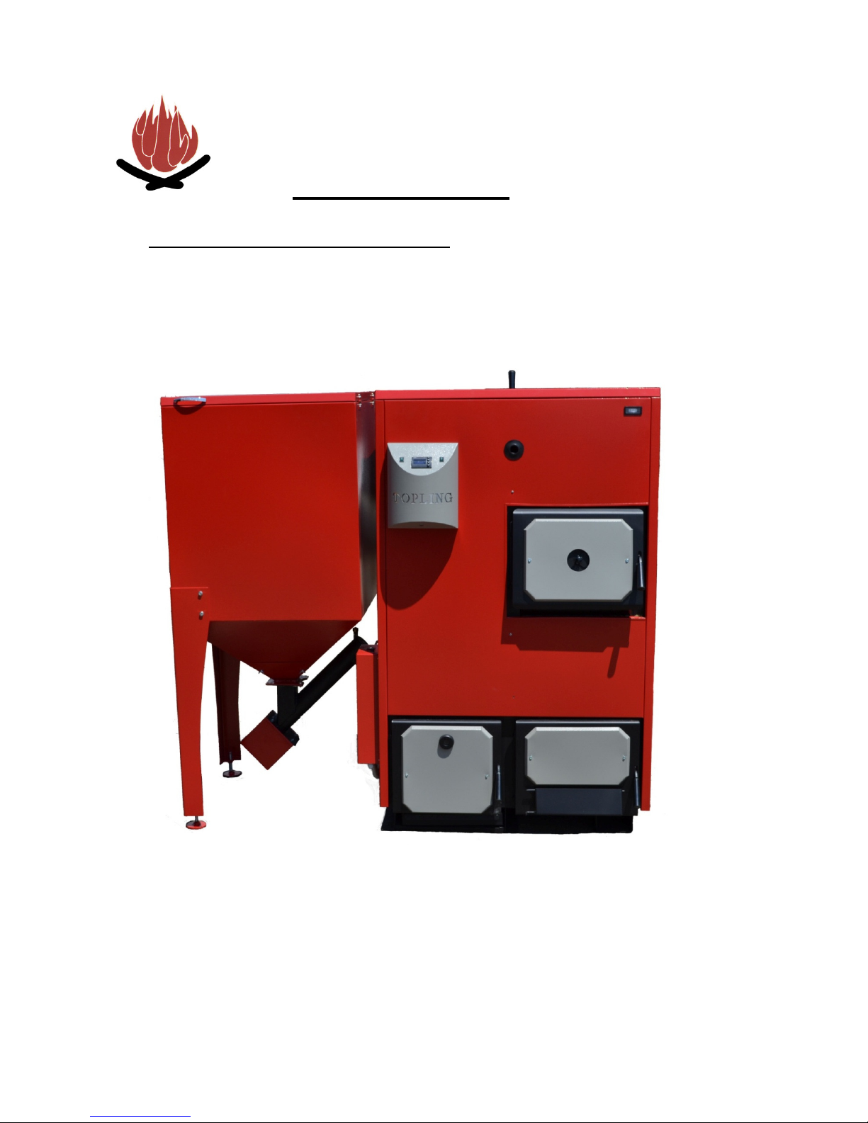
User guide BIOTOPLING-3BT
_______________________________________________________________________________________
TOPLING
P R N J A V O R
www.topling.com; e-mail: [email protected] tel:00387-51/645-200;645-300
USER GUIDE
Combined pellet and solid fuel
hot water boiler
3BT 25 kW
3BT 35 kW
3BT 50 kW
Page 2

User guide BIOTOPLING- 3BT
________________________________________________________________________________________
_____________________________________________________________________________
-2-
TOPLING JUNE 2012 3BT 25-50 kW
LIST OF CONTENTS
page
1. NOTES ON THIS USER GUIDE ..................................................................................... 3
1.1. Introduction ................................................................................................................ 3
1.2. Structure of the User guide........................................................................................ 4
1.3. Glossary ..................................................................................................................... 5
2. SAFETY TIPS ................................................................................................................. 6
2.1. Proper use ................................................................................................................. 6
2.2. Present risks .............................................................................................................. 7
2.3. Used warning and safety signs.................................................................................. 8
2.4. Duty-be informed ....................................................................................................... 9
3. DESCRIPTION AND PURPOSE OF BOILER ............................................................. 10
3.1. Summary ................................................................................................................. 10
3.2. How boiler operates ................................................................................................. 11
3.3. Technical data ......................................................................................................... 12
3.4. Requirements for pellet quality................................................................................. 13
3.5. Declaration of conformity.......................................................................................... 15
4. ASSEMBLY OF BOILER ............................................................................................... 16
4.1. Boiler connection to central heating system ............................................................ 16
5. COMMISSIONING......................................................................................................... 22
5.1. Main characteristics of controller ............................................................................. 22
5.2. Description of reglator operating .............................................................................. 23
6. BOILER MAINTENANCE .............................................................................................. 30
6.1. Cleaning and maintenace ......................................................................................... 30
7. POSSIBLE PROBLEMS IN FUNCTIONING.................................................................. 32
7.1 When can we expect the occurence of fire in pellet storage .................................... 33
7.2 Which steps are to be taken when thermal valve gets activated? ............................ 34
8. FIRST COMMISSIONING.............................................................................................. 35
8.1. Requirements for successful commissioning............................................................. 35
9. DISPOSAL AFTER END OF LIFE ................................................................................ 36
9.1. Dismantling boiler .................................................................................................... 36
9.2. Disposal of boiler...................................................................................................... 36
10. GUARANTEE................................................................................................................. 37
10.1. Period of guarantee.................................................................................................. 37
10.2. Terms of guarantee ...... .......................................................................................... 37
10.3. When the guarantee is not recognised.................................................................. 37
Page 3

User guide BIOTOPLING- 3BT
________________________________________________________________________________________
_____________________________________________________________________________
-3-
TOPLING JUNE 2012 3BT 25-50 kW
1 NOTES ON THIS USER GUIDE
1.1 Introduction
EASY AND SAFE USE
READ USER GUIDE
TECHNICAL CHANGES
RIGHT TO COPY
This guide contain significant information for appropriate and
safe use of hot water boiler type 3BT. If you follow these
Instructions, you can avoid risky situations, reduce maintenance
costs, avoid failure, provide reliability and prolong boiler life.
This User guide must be read and applied by anyone using the
boiler type 3BT.
We keep developing and enhancing our boilers. All information
regarding this Guide that are related to the boiler type 3BT are
correct at the moment of print out.
Before use, all details mentioned herein concerning standards
and legistlation must be checked and compared to standards
and legislation applied in the location where the boiler is to be
installed.
We reserve the right to make changes to boilers that would differ in
technical data and drawings herein.
Written approval of Topling d.o.o. to copy, store in electronic
form, transfer information in electronic format, photography,
translation of this manual in whole or in part is required.
Page 4

User guide BIOTOPLING-3BT
________________________________________________________________________________________
_____________________________________________________________________________
-4-
TOPLING JUNE 2012 3BT 25-50 kW
1.2 Structure of User guide
Tabel 1. Structure of User guide
Chapter
You can find the following here in.....
1. Notes on instructions ... how to use the instructions.
2.
Safety tips
...all related with safety use, what you shoud keep in mind when
using a boiler.
3.
Description and purpose
of boiler
... structure and all about characteristics of boiler, technical data,
what kind of pellet to be used
4.
Assembly of boiler
... how to connect boiler to central heating system.
5.
Commissioning
... how it is commissioned and how to set operating parameters.
6.
Maintenance
... who is in charge of maintance, how to clean and how often.
7.
Possible problems in
operating
...which problems can be experiences in boiler use.
8.
First boiler
commissioning
...requirements for successful commissioning
9. Disposal of boiler after
its life ends
... what should be taken into account when dismantling and
preparing of the boiler for disposal.
10.
Guarantee
... deadlines and terms of guarantee.
Page 5

User guide BIOTOPLING-3BT
________________________________________________________________________________________
_____________________________________________________________________________
-5-
TOPLING JUNE 2012 3BT 25-50 kW
1.2 Glossary
Tabel 2. Explanation of terms
Explanation
Engine gear
Part of system intended for moving pellet screw conveyor.
Screw conveyor
Serves for pellet transporting from reservoire to firebox.
Automatic cleaning
Part of program intended for cleaning firebox just before
damping down a fire.
Display
Display of central unit for furnace operating control
3BT
Boiler with double firebox intended for pellet, solid fuel
(e.g.logs, coal) burning.
Central unit
Logical controller for operation management
Pelet
Type of solid fuel made of sawdust previously dried, then pressed
and in such manner making a cylindrical form with 6 mm diameter
and 20-50mm length.
PP set
System fof preventing fire in pellet reservoire. It is activated if
temperature in pellet feeder pipe exceedes 95˚C.
Draught controller Serves for regulating air quantity entering through bottom flap
into the furnace.
Solid fuel Logs, coal, wooden briquette.
Pellet reservoire
Reservoire for storing a pellet that is transported to firebox by
screw conveyor.
Probe
Serves for detecting certain parameters (temperature, feeder
level, etc.) and forwards them to the central unit for further
processing.
Page 6

User guide BIOTOPLING-3BT
________________________________________________________________________________________
_____________________________________________________________________________
-6-
TOPLING JUNE 2012 3BT 25-50 kW
2 SAFETY TIPS
2.1 Proper use
MAIN PRINCIPLES
MAIN PRINCIPLES OF SYSTEM CONSTRUCTION
The boiler is made in accordance with the known principles of
safe use. Improper use may cause harm, injury or even death
to those who do not comply with safety guidelines as well as to
third parties, which may result in damage to the boiler, and
damage to other resources in the immediate environment
Specialized person who made the boiler installation and
commissioning should demonstrate you how to use it.
Use boiler only when it is completely in order. Use it the right
way and for the purpose for which it is intended, always taking
care of your own safety and the safety of others and the safety
of property. Constantly comply with this manual
Any defect which may impair safety must be immediately
removed.
USE OF BOILER
RELIABLE AND UNRELIABLE USE
The boiler is designed to burn pellet and solid fuel (e.g. wooden
logs, coal). This is possible because the boiler is designed with
double firebox (one for pellet, and other for wooden logs, coal)
Use of any other fuel is not allowed. The manufacturer is not
liable for any damages resulting from improper use. In case of
improper use the responsibility is borne by the one who used
boiler improperly.
As a user, you can enter or alter the operating parameters
within the limits prescribed by these instructions. Entering any
other value of the operating parameters that are not listed in
this leaflet, can lead to errors in the functioning of the system
Page 7
User guide BIOTOPLING-3BT
________________________________________________________________________________________
_____________________________________________________________________________
-7-
TOPLING JUNE 2012 3BT 25-50 kW
ALLOWED FUEL
Only pellet that is made from sawdust is allowed to burn.
Pellet is cylindrically pressed into cylindrical shapes. It is made
from wood residues generated in wood processing. Pellet must
have a standard diameter and length. Chips from which the real
pellet is made, are pressed under high pressure and must have
a low percentage of humidity.
RECOMMENDED
CHARACTERISTICS OF PELET
’’Topling’’ recommends pellet of 6 mm diameter and a 10-30 mm
length. Quality and geometric characteristics of pellets are
prescribed by the German Standard DIN 51731 or Austrian
Standard ONORM 7135
Pay special attention to the quality of pellet, both when
ordering and admissioning.
Use pellet that meets the standards of DIN or ONORM.
For additional information regarding the pellet, see Section
3.4. Requirements regarding fuel quality.
2.2 PRESENT RISKS
Despite of all precautions, the below given risks should be always considered:
Attention!
High temperature surfaces.
Contact with such surfaces may cause burns.
Wait for the boiler to cool to touch these uninsulated surfaces.
Warning!
Danger of choking carbon monoxide.
When boiler is used, carbon monoxide can be emitted through
openings in the boiler.
Do not leave boiler doors open more than required.
Page 8
User guide BIOTOPLING-3BT
________________________________________________________________________________________
_____________________________________________________________________________
-8-
TOPLING JUNE 2012 3BT 25-50 kW
2.3 Used warning and safety signs
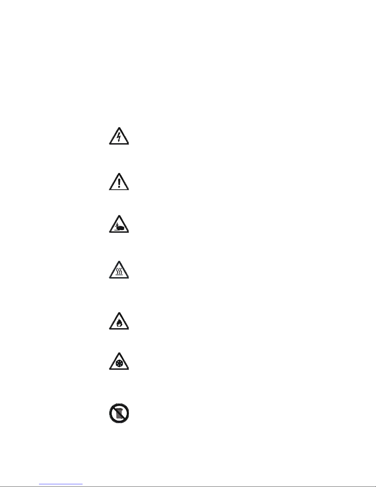
The below listed warning and safety signs are used in the
Instructions:
Danger!
Danger from electrical current.
Work on devices marked with this symbol is only
allowed for the qualified persons.
Warning
Work in areas that are marked with this symbol could
result in serious injury or create significant damage.
Attention
Possible hand injury.
Work in areas marked with this symbol can lead to
hand injuries.
Attention
High temperature surfaces.
Work in areas marked with this symbol can lead to
burns.
Attention
Flammable.
Work in areas marked with this symbol can lead to fire.
Attention
Danger of freezing.
Work in areas marked with this symbol can lead to
freezing.
Notes on proper disposal.
Additional information for operator.
Page 9

User guide BIOTOPLING-3BT
________________________________________________________________________________________
_____________________________________________________________________________
-9-
TOPLING JUNE 2012 3BT 25-50 kW
2.4 Duty- be informed
READING
USER GUIDE Anyone who intends to use the boiler is required to read and understand
this manual, and special attention must be paid to the Chapter II, Safety
instructions. This especially referrs to those who only occasionally use
the boiler, for example, only when cleaning or other tasks related to the
maintenance of the boiler.
This manual must be constantly ''at hand'' where the boiler is installed.
Particular attention should be paid to the standards applicable
to the place where the boiler is installed.
Page 10

User guide BIOTOPLING-3BT
_______________________________________________________________________________________
_____________________________________________________________________________
-- 10 --
TOPLING januar 2011 3BT 25 i 35
3. DESCRIPTION AND PURPOSE
3.1. Summary
Furnace ’’3BT’’ has a modern structure and design, made from quality certified material.
Construction of the boiler is compliant with European Directives:
2006/42/EC, PED 97/23/EC, LVD 2006/95/EC, EMC 2004/108/EC and
European Standards :
EN 303-5:1999; EN 60204-1 : 2006; EN 60335-1:2002; EN 50165:1997 +A1; EN 61000-63:2001; EN ISO 12100:2010;EN 287-1: 2004, EN 15014-1; EN10204:2004;EN ISO 7000 :2004
Boiler testing was done according to EN 303-5 and meets all requirements for connection to the
central heating system.
Hot water boiler is designed for heating of small residential units, family houses, shops and
small manufacturing units.
Automatic operation of the boiler provides the user with an enviable comfort considering that
you need to take into account only the charge of pellet reservoir, which makes it suitable for
widespread use.
Pellet is an environmentally clean fuel produced from sawdust. Sawdust is initially dried and
then pressed under high pressure. The final product is fuel of exceptional calorific power and
pure composition with no chemical additives. The percentage of ash in the combustion of pellets
is very low and amounts to 1%.
Calorific power of pellet is about
18000 k
J/kg
, which means that
2 kgs of
pel
let
corresponds to 1l of heating oil.
Operating the boiler is a very simple and means only turning on over the master switch and
setting the desired temperature.
From a functional point of view the pellet boiler is not behind the oil or gas heating systems,
while in fuel consumption it is significantly more cost-effective.
Compared to boilers with heating oil the savings with pellet boilers is up to three times. Pellet is
renewable, which means that, as such, is environmentally friendly.
Pellet tank is an integral part of the boiler plant and needs to be recharged as needed.
The firebox and convective part of boiler are made of quality sheet metal by welding
technology. The boiler is well insulated with hard-pressed mineral wool in a quality tin plating.
Assembly and commissioning of the furnace are simple, and the connectors are standard.
Boiler is tested for water resistance. Allowable working pressure is 2.5 bar.
Page 11
User guide BIOTOPLING-3BT
________________________________________________________________________________________
_____________________________________________________________________________
-- 11 --
TOPLING JUNE 2012 3BT 25-50 kW
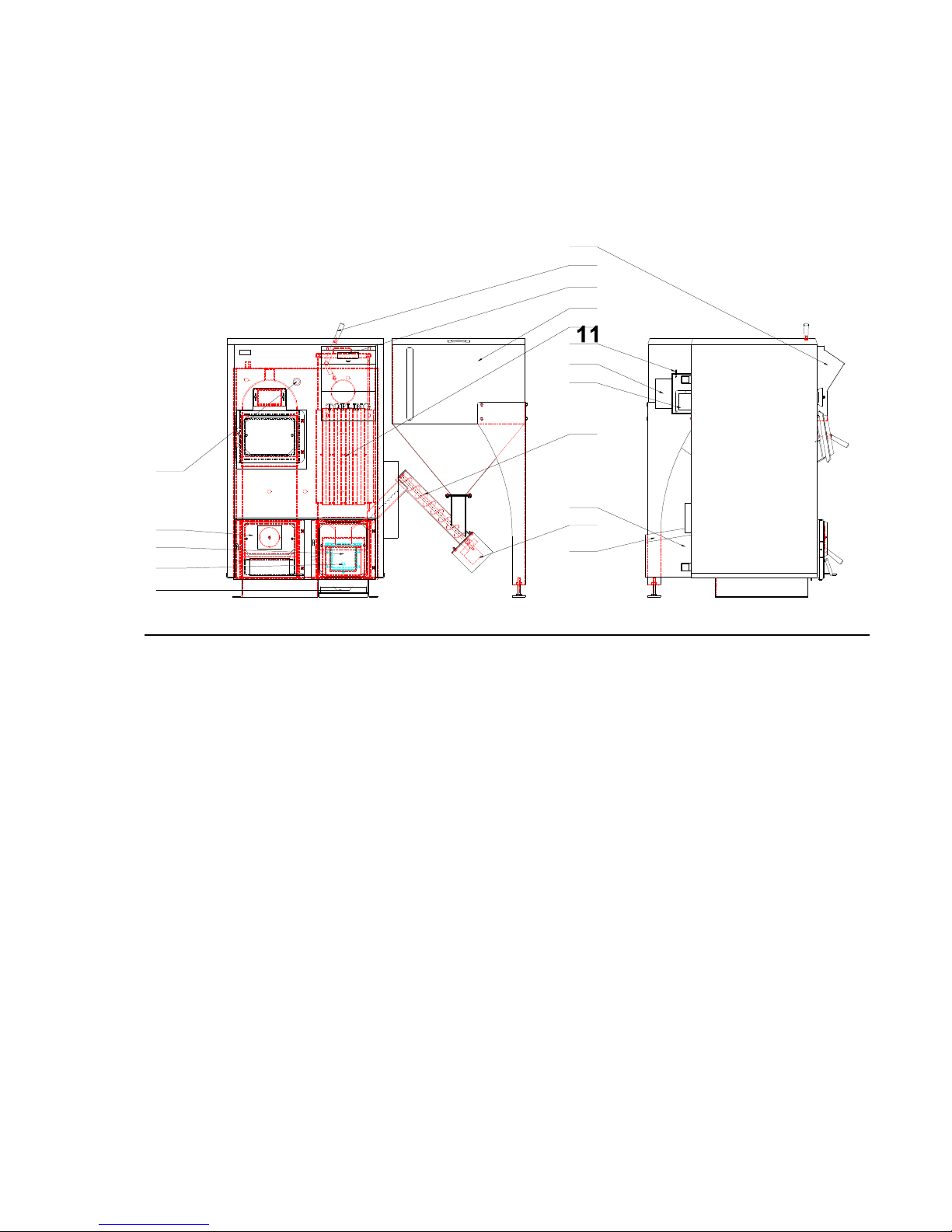
3.2. How the boiler operates
BOILER TYPE 3BT
12
15
6
3
2
13
10
4
8
5
7
9
1
16
14
17
Figure 1. Parts of boiler
LEGEND
1. firebox 9. firebox doors
2. convective beam 10. chimney
3. pellet reservoire 11. probe of flue gases
4. screw conveyor 12. box with operating display
5. motor of screw reductor 13. flue pipe
6. flap of convective beam 14. ash collector
7. air feeder 15. convective beam cleaning mechanism
8. fan 16. heater to fire pellet
17. connection for draught control
Boiler operation when pellet is used as fuel
From pellet reservoire Fig.1 pos.3 a screw conveyor Figure 1 position 4 inserts pellet into
firebox Fig.1 pos.1.
Electric heater, which is located in the firebox Fig.1 pos.16 is used to fire pellets. This occurs
only in the initial stage of commissioning of the boiler in operation and after a long break.
Fan Fig.1 pos.8 supports pellets burning in a way that it leads required amount of oxygen for
combustion into firebox.
Page 12
User guide BIOTOPLING-3BT
________________________________________________________________________________________
_____________________________________________________________________________
-- 12 --
TOPLING JUNE 2012 3BT 25-50 kW
Boiler operation when wood or coal is used as fuel
In this case, the furnace firebox for wood or coal is active. The fire is put manually to the lower
door (Figure 1 position 9). Firing chopped wood or coal is done through the upper door of the
boiler. In this case, automatied functions of boiler are off. Feeding the boiler is done manually
and fuel should be filled every 2 to 5 hours, depending on the quality of the wood
(coal). Draught regulator (not supplied with the boiler) is set to the desired temperature of boiler
water which should be within the limits of between 60-90 0C.
A
B
H
R1
E
R1
R3
D
R2
C
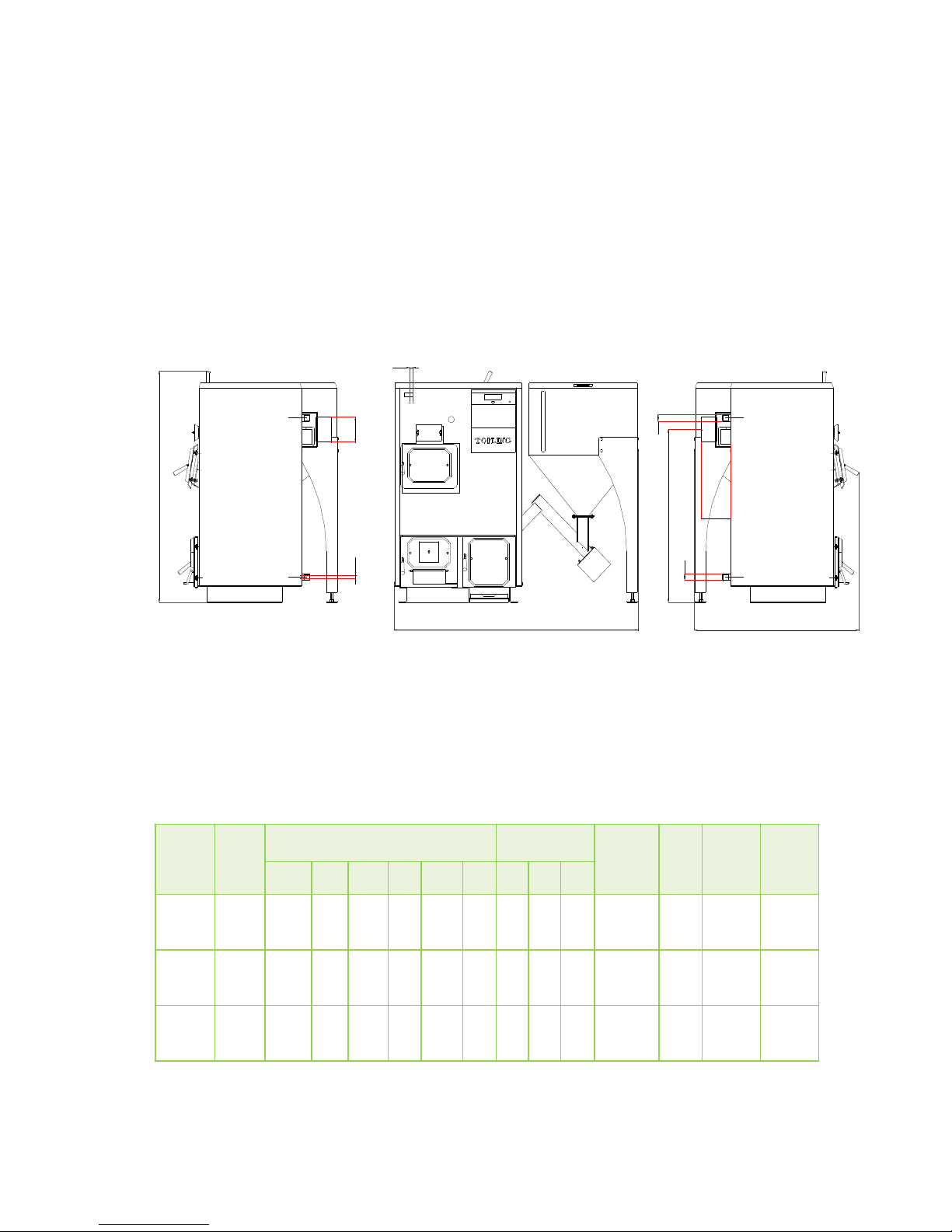
Figure 2. External appearance of furnace
3.3. Technical data
Tabel 3. Technical data
TYPE
Power
[kW]
DIMENSIONS [mm]
ACCESORIES
[col]
Required
draught
[Pa]
Boiler
weight
+
reservoi
re
[kg]
Water
content
[ l]
Capacity
of pellet
reservoire
[kg]
A
B C D H E R1 R2 R3
3 BT-25 25
1623
1093
1474 160
1101
196 5/4 3/4
1/2
21
634 213 230
3 BT-35 35
1740
1100
1650 180
1286
230 6/4 3/4
1/2
25 890
310 290
3 BT-50 50
2135
1185
1752 200
1326
253 6/4 3/4
1/2
28 1025 410 290
Page 13

User guide BIOTOPLING-3BT
________________________________________________________________________________________
_____________________________________________________________________________
-- 13 --
TOPLING JUNE 2012 3BT 25-50 kW
paramete
r unit 3
BT25
3BT35
3BT50
Max. power kW 25 35 50
Nominal boiler power kW 8-25 11-35 16-50
Coefficient of efficiency % 91 91 91
Working pressure of boiler bar 2.5 2.5 2.5
Test pressure bar 5 5 5
Temperature at the boiler entrance
0
C 70 70 70
Temperature at the boiler exit
0
C 90 90 90
Water content l 213 310 410
Boiler category according to EN 303-5
3 3 3
Resistance on the water side at
nominal load
- ∆t=10 K
- ∆t=20 K
hPa
7
2
7
2
7
2
Required operating pressure Pa 21 25 29
Mass flow of flue gases:
-nominal load
-partial load
kg/s
0.0176
0.0079
0.0350
0.0160
0.510
0.335
Temperature of flue gases:
-nominal load
- partial load
-max. load
0
C
135
65
170
129
95
180
129
95
180
Capacity of pellet reservoire [kg] kg 230 290 290
Starting flow col 5/4 6/4 6/4
Return flow col 5/4 6/4 6/4
Opening for filling and emptying col 3/4 3/4 ¾
Electrical power:
-under normal regime
-in incineration phase
W
100
300
123
323
123
323
Electrical components:
-power
-power supply at normal operation
- power supply in incineration phase
V
A
A
230
1.0
2
230
1.0
2
230
1.0
2
3.4. Requirements for pellet quality
GERMAN STANDARD
DIN 51731
Pellet in group of size HP5 is made of pressed wood chips of
intact wood including bark, with no additional bonding
materials. The energy that is contained in 2 kgs of pellet
corresponds roughly to the energy contained in 1 liter of heating
oil (10 kWh).
Page 14

User guide BIOTOPLING-3BT
________________________________________________________________________________________
_____________________________________________________________________________
-- 14 --
TOPLING JUNE 2012 3BT 25-50 kW
AUSTRIAN STANDARD
ÖNORM M 7135
Austrian standard contains requirements regarding the quality
of pellets, pellet testing procedures, the method of pellet
production control and labeling of the same.
DIN
PLUS STANDARD
Standard DINplus is a combination of the two previous
standards.
Certification procedures is performed by the pellet manufacturer
verified by a body that has a DIN Certco. Independent testing
should be carried out at regular intervals in order to ensure the
required quality of pellet.
PELLET CHARACTERISTICS
Tabel 4. Pellet characteristics
Standard
DIN 51731
ÖNORM M 7135 DINplus
AS/NZS 4014.6
Length
max. 50 mm
max. 5 x Ø
max. 5 x Ø
max. 38 mm
Diameter Ø
4 – 10 mm
max. 10 mm
4 – 10 mm
max. 10 mm
Energy value
17.5 - 19.5 MJ/kg min. 18.0 MJ/kg min. 18.0 MJ/kg 18.0 - 21.0 MJ/kg
Pellet density
1.0 – 1.4 kg/dm
3
min. 1.12 kg/dm
3
min. 1.12 kg/dm
3
N/A
Bulk density
min. 650 kg/m
3
min. 650 kg/m
3
N/A min. 640 kg/m
3
Water content
max. 12%
max. 10%
max. 10%
max. 8%
Ash content
max. 1.5%
max. 1.5%
max. 0.5%
max. 0.5%
Abrasion of pellet N/A max.2.3% max.2.3%
N/A
Sulphur content
N/A
max. 0.04%
max. 0.04%
N/A
Nitrogen content
N/A
max. 0.3%
max. 0.3%
N/A
Chlorine content
N/A
max. 0.02%
max. 0.02%
N/A
Page 15

________________________________________________________________________________________
_____________________________________________________________________________
TOPLING
JUNE 2012
3.5. Declara
tion of Conformity
DEC
LARA
We
.................…………………….... :
hereby declare under own responsibility that the product
label
........ ................................... :
Type
/ Model.. .................................... :
Date of production .......
.................. : 2012
to which this Declaration applies to, is:
in accordance with EC Dire
ctives
2006/42/EC
PED 97/23/EC
LVD 2006/95/EC
EMC 2004/108/EC
Applied harmonised standard
s, in particular
EN 303
EN 50165:1997 +A1; EN 61000
Other mentioned standards and technical
EN 287-1: 2004, EN 15014-1
;
Applied procedure for
evaluation of conformity
The limit value of emissions of combustion products
Issued certificates:
EC
Accredited laboratory
: TÜV Thüringen e. V.
Industriestr. 13
98544
We hereby declare that the above named product in its concept and workmanship, is in accordance with
the security and safety standards that comply with the above
Thereby all operating conditions and application requirements are in accordance with the
technical documentation.
Once a single change has been made to the product not in agreement with us, this statement loses its
importance.
Place and date
Prnjavor
................................................
EC
-
DEKLA
User guide BIOTOPLING
-- 15 --
TION OF
CONFORMITY
in compliance with EN45014:1998
TOPLING
Vijaka bb
78430 Prnjavor
Bosnia and Herzegovina
:
hot water boiler
3BT-25, 3BT-35, 3BT-50
:
- Directive on machinery
- Pressure Equipment Directive
- Low Voltage Directive
- Electromagnetic Compatibility
Directive
:
-5:1999; EN 60204-1 : 2006; EN 60335-
1:2002;
-6-3:2001;
EN ISO 12100
specifications:
EN 10204:2004; EN ISO 7000 :2004;
: Modul
(Category
): ________
control of type-Certificate No. ____________
Service-
Center Südthüringen
Zella-Mehlis
directives and standards.
Full name and title of signatory
Živanić Radislav, Direc
tor
LS
....................................................
-3BT
3BT 25-50 kW
:2010
e B1
User guide and
:
Page 16
User guide BIOTOPLING-3BT
________________________________________________________________________________________
_____________________________________________________________________________
-- 16 --
TOPLING JUNE 2012 3BT 25-50 kW
4. BOILER ASSEMBLY
4.1. Boiler connection to central heating
system
Boiler connectioning should be performed only by skilled and authorised persons.
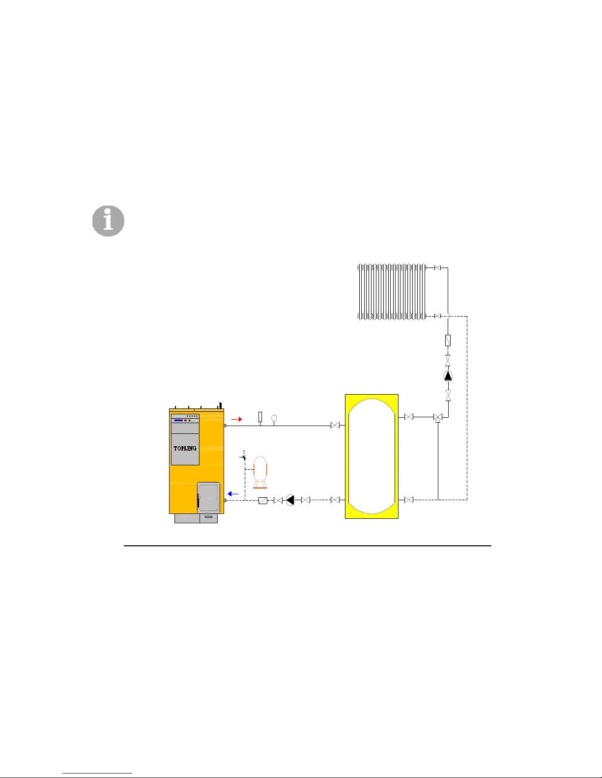
M
T
Figure 3. (scheme of connecting boiler to the system)-version 1, with heat battery
Page 17
User guide BIOTOPLING-3BT
________________________________________________________________________________________
_____________________________________________________________________________
-- 17 --
TOPLING JUNE 2012 3BT 25-50 kW
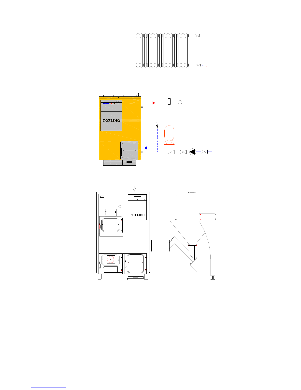
M
T
Figure 4. (scheme of connecting boiler to the system)--version 2, no heat battery
Fuel (pellet) reservoire is an integral part of the equipment and is supplied with the boiler and
are bonded by flange.
Page 18
User guide BIOTOPLING-3BT
________________________________________________________________________________________
_____________________________________________________________________________
-- 18 --
TOPLING JUNE 2012 3BT 25-50 kW
Furnace is preferably placed as close as possible to the chimney.
Do not close free air supply to the boiler.
WARNING
- The furnace must be placed on a stable, flat surface. Setup
and installation of the furnace must be conducted by a
professional.
- Water supply connections must be provided in the furnace
room, plus a connection for possible drainage and electrical
connection with mandatory grounding.
- The furnace room should have natural ventilation that provides
fresh air.
- The floor and inside the boiler room must be made of fireproof
materials.
It is desirable that the room is not damp, in order to avoid the corrosion of metal parts, with the
goal of extending life.
Softened water is recommended for filling the boiler from the system.
Circulation pump is put into operation only when the heating system is filled with water. What
must be taken into account is that the system is vented.
When connecting the furnace and chimney, the flue pipe should be placed horizontally or
vertically. All connections must be well sealed.
Before the first firing, it is necessary to check whether the chamotte is properly placed in the
furnace and check that the transportation and installation of the boiler has not caused
movement of refractory bricks.
The chimney must be sized according to the diagram in Figure No. 5.
Insufficient airflow, ie. when geometric features of chimney as indicated in Figure 5 herein have
not been met, there is a real risk of transmission of the flame from the firebox into the pellet
feeder tube, and then in the pellets reservoire which can cause a fire.
Page 19

User guide BIOTOPLING-3BT
________________________________________________________________________________________
_____________________________________________________________________________
-- 19 --
TOPLING JUNE 2012 3BT 25-50 kW
Chimney size for furnaces type 3BT
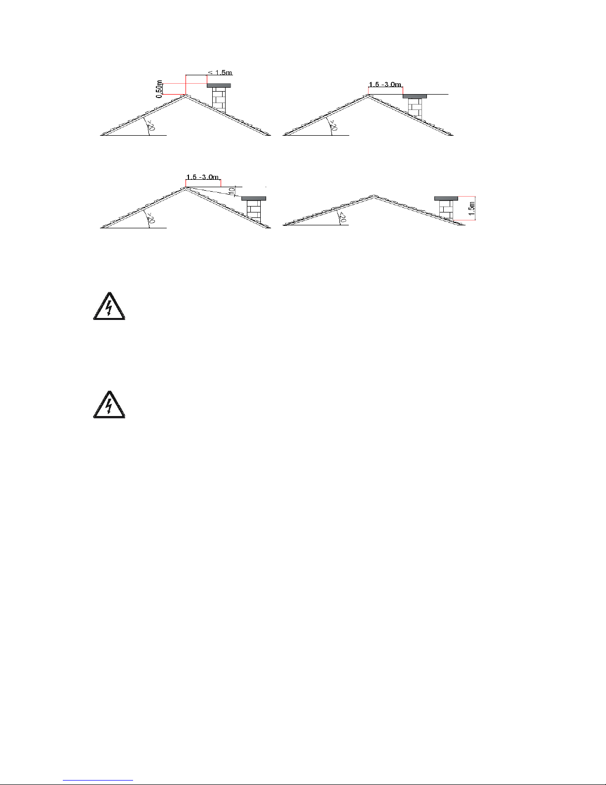
For a good and safe operation of the furnace a chimney should be sized according to the
diagram in Figure 5. Figure 6 shows the proper placement of the chimney over the roof.
Figure 5. Selection of chimney section for boiler 3BT
Rated power of boiler in
[kW]
C
ombin
ed boiler
3BT
with
required draught and
temperature of flue gases at
exit from boiler tw<2500C
Light diameter of chimney in
cm
Required pressure drop in boiler [N/m
2
]
Useful chimney heights in [m]
Page 20
User guide BIOTOPLING-3BT
________________________________________________________________________________________
_____________________________________________________________________________
-- 20 --
TOPLING JUNE 2012 3BT 25-50 kW
Figure 6. Samples of properly set and dimensioned chimneys
Connecting the control panel of boiler to the network
When installing the boiler, power supply cord must be connected to the boiler. The power supply
is single-phase 220 V, 50 Hz. Installation must be performed by an expert because there is a
danger of electrical shock.
Connection of room thermostat
The room thermostat can be connected to a furnace panel.
Installation has to be performed by an expert because there is a danger of electrical shock.
Before putting into operation the work You must check:
- the pressure in the boiler and installation,
- whether complete installation is properly vented,
- whether boiler cables do not rely on the warm (hot) portions of the boiler or the cables are not
physically damaged,
- whether furnace fireclay is properly positioned (Figure 7),
- before feeding pellets into the reservoire, check that there are no mechanical hard objects that
could impede the work of the screw conveyor.
Page 21

User guide BIOTOPLING-3BT
________________________________________________________________________________________
_____________________________________________________________________________
-- 21 --
TOPLING JUNE 2012 3BT 25-50 kW
Figure 7. Distribution of refractory elements in the furnace firebox for combustion of pellets
In a closed heating system the installation of a certified safety valve opening pressure of 2.5
bars is required, and installation of expansion vessel. Locking element must not be installed
between the safety valve, expansion vessel and boiler.
Water temperature in boiler may not fall below
550C not to cause condansate
.
In the event of severe winter weather and low temperature, and when the boiler is not used it is
necessary to drain waiter from the system or fill it with antifreeze liquid.
Page 22
User guide BIOTOPLING-3BT
________________________________________________________________________________________
_____________________________________________________________________________
-- 22 --
TOPLING JUNE 2012 3BT 25-50 kW
5. COMMISSIONING
5.1. Main characteristics of controller
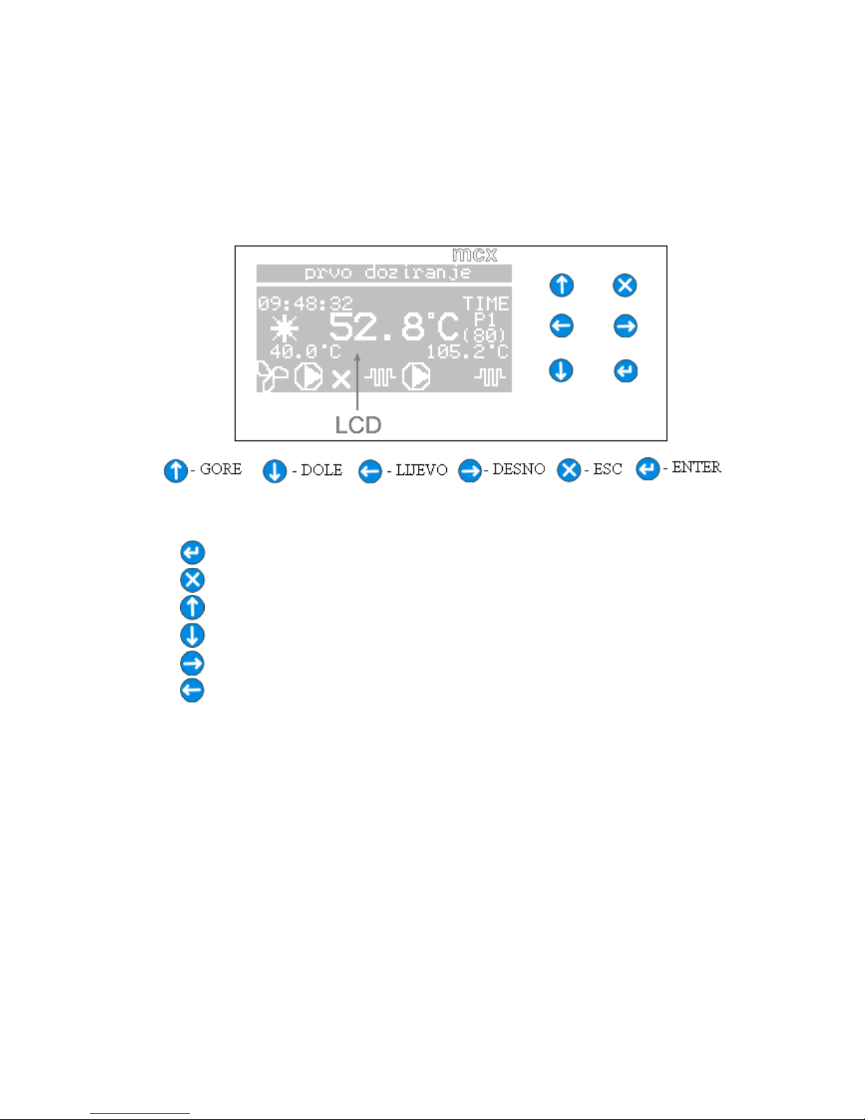
The controller is designed for boiler operation which uses pellet and solid fuel, andl
boiler additionally owns two electric heaters total power of 18 kW.The appearance of the front of
the controller is shown in the figure below.
Slika 8. Front side of the controller
The controller has LCD 128 x 64 pixels and six buttons on the right. Function of buttons
is as follows:
- confirmation of set parameters, menu overview and boiler turn on,
- listing menu and shutting down the boiler,
- setting parameters,
- setting parameters,
- menu overview and access to user’s paramenters,
- menu overview.
Inputs of controller are as follows:
- boiler water probe (Pt1000),
- flue gas probe on pellet side of the boiler (Pt1000),
- flue gas probe on solid fule side of the boiler (Pt1000),
- boiler side of hot water (NTC, 10KΩ),
- room thermostat.
Outputs of controller are as follows:
- electrical heater for pellet firing (relay, 16 A, NO),
- screw conveyor (relay, 16 A, NO),
- heating system pump (relay, 8 A, NC),
- pump for hot water boiler (relay, 8 A, NC),
- electrical heaters, 2 x 9 KW (relay, 8 A, NO),
- fan (PWM).
Page 23
User guide BIOTOPLING-3BT
________________________________________________________________________________________
_____________________________________________________________________________
-- 23 --
TOPLING JUNE 2012 3BT 25-50 kW
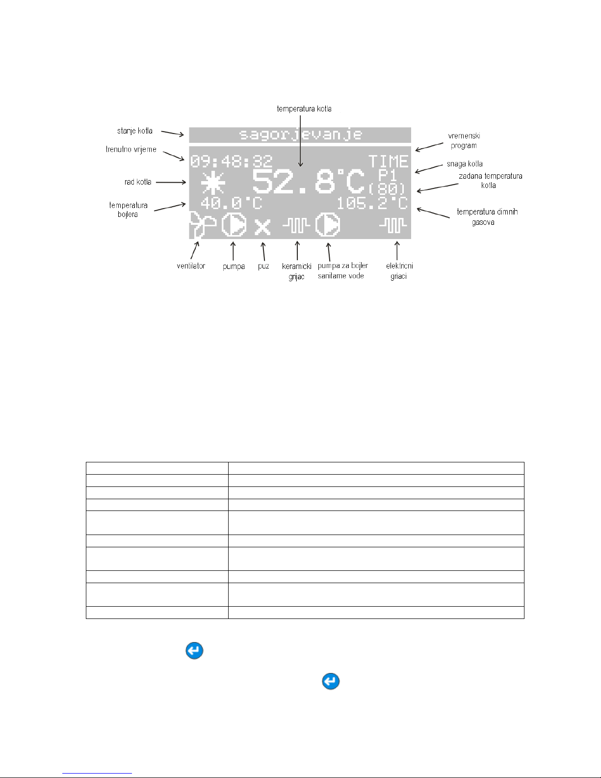
The belov given figure describes a meaning of certan symbols, numbers and displayed
images on main display of user interface.
In the upper line, „STATE OF BOILER“ the information on the current stage of the boiler
(boiler off, the first ignition, combustion, room therm. off, ...) are alternately printed, and on the
selected type of fuel that the boiler uses. Symbol „OPERATION'' means that the boiler is on or
off. If the boiler is set to run at a set time program the TIME is displayed. Symbols in the bottom
line of the display show the state of controller output, or whether the executive components (fan,
heating system pump, feeder conveyor, heater, boiler hot water pump and electric heaters) are
on or off. The existence of a particular symbol means that the element is turned on.
5.2. How the controller operates
There are many different combinations related to the type of fuel that the boiler can
use. The following table describes the meaning of each item of the display FUEL TYPE.
Tabel 5. Possible operations of combined boiler
Type of fuel Meaning
PELLET Pellet used as fuel
WOOD Designed to burn solid fuel
EL. HEATERS Electrical heaters of 2 x 9 KW are used
WOOD THEN PELLET
In case you want to use the pellet boiler after combustion of
solid fuels.
WOOD AND PELLET For simultaneous firing of solid fuel and combustion of pellets.
WOOD THEN EL. HEATERS
In case you want to use electric heaters after combustion of
solid fuels.
WOOD AND EL. HEATERS For simultaneous electric heaters and solid fuel heating.
PELLET THEN EL.
HEATERS
In case you want to use electric heaters when pellet runs out.
PELLET AND EL. HEATERS For simultaneous use of electric heaters and pellet heating.
After the type of fuel is selected, the boiler should be started. The boiler is turned on by
pressing the button for two seconds, unless START appears on display. Previously it is
required to turn on the main, red switch on the boiler. The boiler is set to work at the defined
time program when you press again the button for two seconds, unless VREMENSKI
PROGRAM (TIME PROGRAM) appears on display. The boiler is turned off by pressing the
Page 24
User guide BIOTOPLING-3BT
________________________________________________________________________________________
_____________________________________________________________________________
-- 24 --
TOPLING JUNE 2012 3BT 25-50 kW
button for two seconds, unless STOP appears on display. In the event that the fuel type
"WOOD THEN PELLET" is selected, after each boiler feeding with solid fuel, it is necessary to
choose the TYPE OF FUEL on display, and re-select "WOOD THEN PELLET". The same
should be done in the case the fuel type "WOOD THEN EL. HEATERS“ is selected. The
objective of this action is to reset the timers significant for automatic startup of pellet boilers, or
electricity boiler. On the display "EL. HEATERS POWER" the number of electric heaters that will
be loaded if "EL. HEATERS“ is selected as a fuel (0KW, 9KW, 18 KW). The existence of symbol
"electric heaters" means that one or both electric heaters (9 KW and 18 KW) are involved.
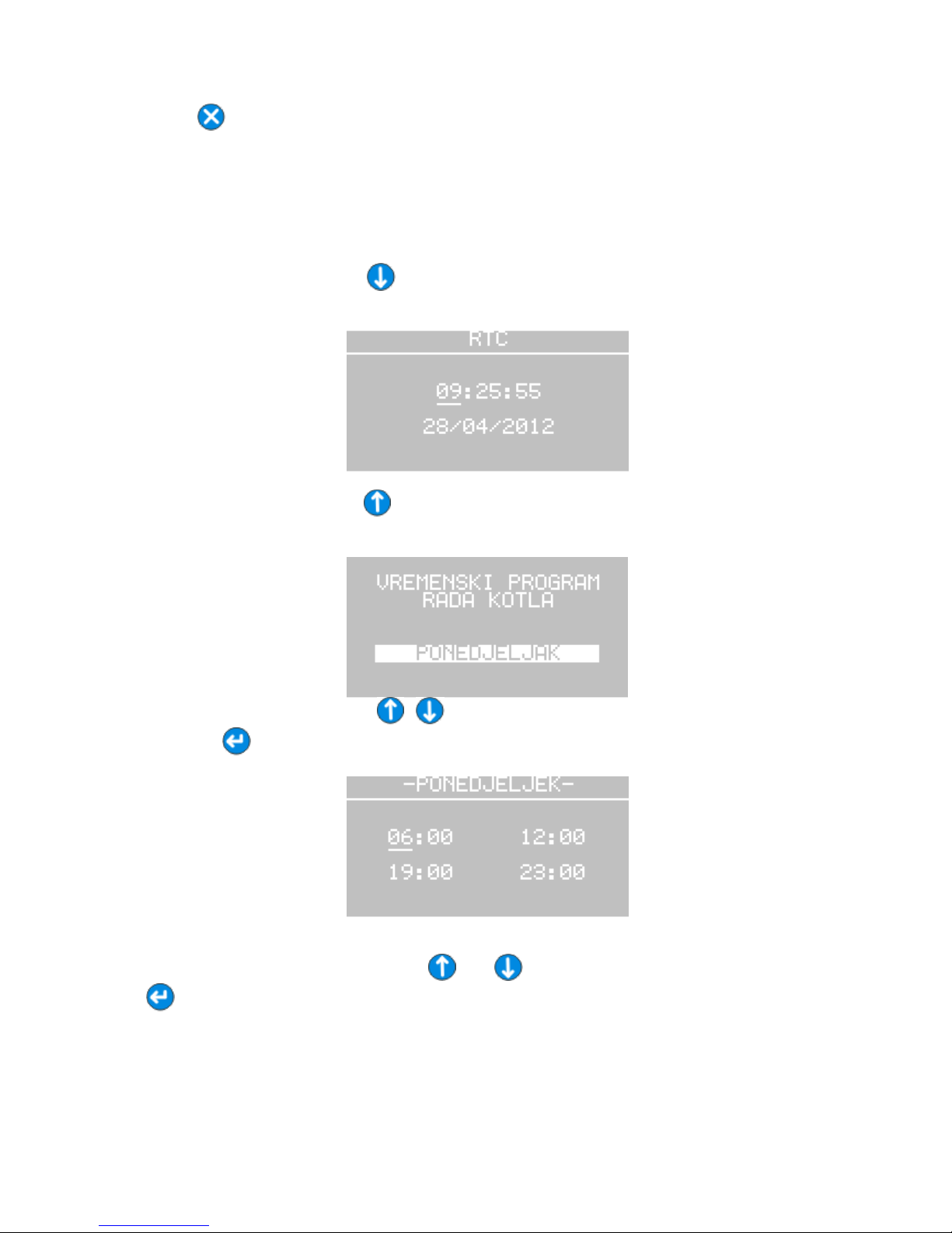
By pressing the button for two seconds you enter into display where time and date
are set.
By pressing the button for two seconds you enter into display where boiler operation
time program is set.
By pressing the buttons , date of certain time program is set, and by pressing
the button settings for selected date are done.
The values shown on the display represent the time within which the boiler will be in use.
Values are set by pressing the buttons and , and are confirmed by pressing the button
, and an underscore (_) is shown under currently active variable. Settings can be made
independently for each day, and there are two time intervals for the boiler use for every single
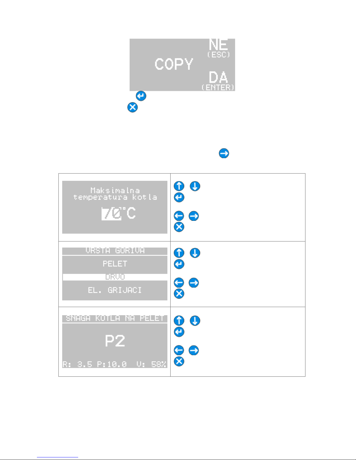
day. After you finish entering the last value in the time program the form that asks if you want to
copy the same time pattern for the next day of the week is shown on display.
Page 25
User guide BIOTOPLING-3BT
________________________________________________________________________________________
_____________________________________________________________________________
-- 25 --
TOPLING JUNE 2012 3BT 25-50 kW
By pressing the button the same time pattern for the following days is confirmed,
and by pressing the button it is cancelled and you are directed to settings for the time
pattern for the following day.
There are two groups of parameters relevant to the operation of the boiler, quality of
pellet combustion, emission of fumes, etc. One group represents service parameters that are
set by an authorized person at start-up of the boiler. The other group are user's parameters that
the the end user sets, and can be set by pressing the button . The list of user's parameters
is shown in table below.
, - sets desired value.
- confirms set value and starts setting the
next parameter.
, - lists the menu.
- returns to the main menu.
, - fuel type selection.
- confirmation of selected fuel and setting
the next paramenter.
, - lists the menu.
- returns to the main menu.
, - selection of pellet boiler power.
- confirmation of selected power and setting
the next paramenter.
, - lists the menu.
- returns to the main menu.
Page 26

User guide BIOTOPLING-3BT
________________________________________________________________________________________
_____________________________________________________________________________
-- 26 --
TOPLING JUNE 2012 3BT 25-50 kW
, - izbor snage elektro grijača.
- confirms selected power and setting the
next paramenter.
, - lists the menu.
- returns to the main menu.
, - sets desired value.
- confirmation of set value and setting the
next paramenter.
, - lists the menu.
- returns to the main menu.
, - sets desired value.
- confirmation of set value and setting the
next paramenter.
, - lists the menu.
- returns to the main menu.
The course of the boiler executive elements action is divided into several stages in order
to ensure reliable operation of the boiler, the optimal combustion, satisfactory flue gas
emissions to the higher utilization factor. The boiler’s operation is divided into three main phases
including: ignition, stabilization and combustion. In order to facilitate understanding of the
process of the boiler’s operation when reading the text, the figure 9 should be observed at the
same time.
When starting the boiler, if the actual flue gas temperature is above the fixed limits for
incineration, it is considered that the furnace has enough ember to continue burning pellets and
no electric heater is started, but continuous pellet dosing keeps going. If the temperature of the
flue gases is below the fixed limits for firing, then the firing process begins. In the firing process
initially only the fan is involved to clean the firebox partially, primarily to clean the front of the
heater.Afterward, the feeder conveyor that feeds in initial quantity of pellets for firing is involved
(K2). During the initial pellet dosing an electric heater is involved that continues to work after
feeder conveyor is stopped, and fires the pellet in the furnace over the next several
minutes. Shortly after firing pellet the flue gas temperature begins to grow. This increase in the
temperature of flue gases transfers the operation process in stabilization phase, when the
electric heater gets off. At this stage the pellet dosage is done by a reduced mode, while the fan
is running with slightly more power than at the combustion stage (to be configured in the service
parameters).
The purpose of the stabilization phase is that the pellet burning is spread throughout the
combustion chamber. Duration of the stabilization phase is scheduled, after which it goes into
operating mode, in the phase of combustion. If there is no required increase in the flue gas in
specified time in the phase of incineration, the pellet is considered not fired and boiler stops
working. In this case, at the line “state of boiler“ the FAILURE is displayed.
Page 27

User guide BIOTOPLING-3BT
________________________________________________________________________________________
_____________________________________________________________________________
-- 27 --
TOPLING JUNE 2012 3BT 25-50 kW
At the stage of combustion, the pellet and air dosing is done as set in the user settings (K5, K6
and K7). By approaching the current boiler temperature to the parameter '’maximum boiler
temperature'' the boiler starts to decrease power continuously in order to minimize offs and
ons. The boiler goes into a resting phase when the temperature of the boiler water reaches the
value set in parameter ’'maximum boiler temperature''. Then in the line ’’state of boiler’’ the
SLEEPING MODE is displayed. From resting stage the boiler restarts when the boiler water
temperature drops below the parameter ''maximum boiler temperature'' for a certain difference
set in service parameters. Whether the operation of the boiler shall continue after the
stabilization phase, or the firing process shall begin, depends on the current temperature of flue
gases.
If you are using a room thermostat, it can be set that boiler stops working when the room
thermostat gets disconnected, or that the boiler keeps operating for a defined period of time. If
the boiler keeps operating for some time, the temperature will reach the set temperature of the
boiler very soon and the boiler will stop working.
Heating system pump is activated when the boiler temperature is higher than the set
pump temperature (S21 parameter) and if the room thermostat is fitted . If the room thermostat
switches off, the pump may still be active for a while (5 minutes) and then turns off until restart
of the room thermostat is activated.
Page 28

User guide BIOTOPLING-3BT
________________________________________________________________________________________
_____________________________________________________________________________
-- 28 --
TOPLING JUNE 2012 3BT 25-50 kW
Figure 9. Principal diagram of boiler operation
K1 – maximum boiler temperature, K2 – initial pellet feeding time, K3 – duration of first
incineration, K4 – fan power at incineration, K5 – operation time of feeder conveyor, K6 – break
of feeder conveyor, K7 – fan power at burning, S1 – time of initial blow out, S2 – fan power at
Page 29
User guide BIOTOPLING-3BT
________________________________________________________________________________________
_____________________________________________________________________________
-- 29 --
TOPLING JUNE 2012 3BT 25-50 kW
at blow out, S3 – fan power at initial feeding, S4 – early involvement of the heater, S5 –
duration of second incineration, S6 – duration of stabilisation phase, S7 – operation time of
feeder conveyor at stabilisation, S8 – break time of feeder conveyor at stabilisation, S9 – fan
power at stabilisation, S10 – period of stabilisation prolongation, S11 – time for firebox
cleaning, S12 – fan power at firebox cleaning, S13 – delay of boiler switching off after the
room thermostat is disconnected, S14 – fixed limits for firing, S15 – required increase in
temperature of flue gases, S16 – minimum temperature of flue gases, S17 – allowed flue gas
temperatures drop, S18 – the beginning of a reduced dosing regimen, S19 – exceeding factor,
S20 – difference for the boiler operation, S21 –temperature for the pump startup, S22 –
difference for pump operation, S23 – maximum temperature of the boiler, S24 – difference
between the boiler and the furnace.
NOTE
These instructions must be followed to ensure safe and proper installation,
operation and maintenance of the boiler. Anyone who install, operate and
maintain the boiler must carefully read this manual before using the boiler and
properly treat it. Ignoring this instruction may lead to invalidating the warranty.
FIRE RISK
No flammable materials or liquids should be kept in the immediate vicinity of the
boiler.
RISK TO LIFE
Insufficient air supply to the plant can result in exposure to hazardous flue gases in
a room where the boiler is placed. It is necessary to make sure that openings for
fresh air and exhaust waste are not reduced or closed. If this problem is not
resolved immediately, the boiler must not be in use.
Page 30

User guide BIOTOPLING-3BT
________________________________________________________________________________________
_____________________________________________________________________________
-- 30 --
TOPLING JUNE 2012 3BT 25-50 kW
6. BOILER MAINTENANCE
6.1. The frequency of Cleaning and
Maintenance
In order to enable long life expectancy of the boiler without any operation interruptions,
it is necessary to regularly clean and maintain the boiler. In this way you will avoid costly
repairs. Keeping your firebox clean is the basic condition for the good boiler operation. A layer
of soot and tar accumulates on the firebox walls and it is necessary to mechanically clean the
furnace.
The frequency of the maintenance depends on the quality of pellet and the power of the
boiler. Generally, it is necessary to observe the frequency of maintenance described in the
table.
Turn off the automation of the boiler and the boiler main switch before the
operations described in the table below.
Table 6. The frequency of Cleaning and Maintenance
Interval
Component
How
it is performed
Every three days Clean the convective beam Move the handle for cleaning on the
mechanism for cleaning the convective
beam (Fig. 1, position 15) forward backward. It is necessary to move the
handle forward-backward for five to six
times.
Every seven days (for
firebox used for
combustion of wood or
coal)
Clean the internal exchange
surface of the layers of soot
Use the cleaning kit shown in Fig.14 to
scrape loot layers from the walls of the
firebox
Monthly Clean the pellet storage Regardless of the pellet quality, a
certain amount of pellet dust remains
on the walls and bottom of the storage
During the cleaning it is necessary to
use or remove all pellet from the
storage, and then suck up the dust with
a vacuum cleaner.
Every six months Clean the automation display Cleaning should be done with well
wrung-out damp cloth
Check whether the chimney ,
flue pipe elbow, chimney
pipe are clean and if
necessary clean them.
Wait for the boiler to cool down,
dismantle the flue pipe, flue gas
channel and smoke outlet elbow and
perform the cleaning with the same kit
which is delivered with the boiler
Check the water probe of the
boiler and the probe of flue
gas and if necessary clean
them
Carefully take out the probes out of
their location and if necessary clean
them of soot layers (for flue gas probe)
and of possible lime scale (water probe
of boiler)
Annually Thorough annual cleaning at
the end of the heating
season.
Clean all the components described in
the upper part of the table
Page 31
User guide BIOTOPLING-3BT
________________________________________________________________________________________
_____________________________________________________________________________
-- 31 --
TOPLING JUNE 2012 3BT 25-50 kW
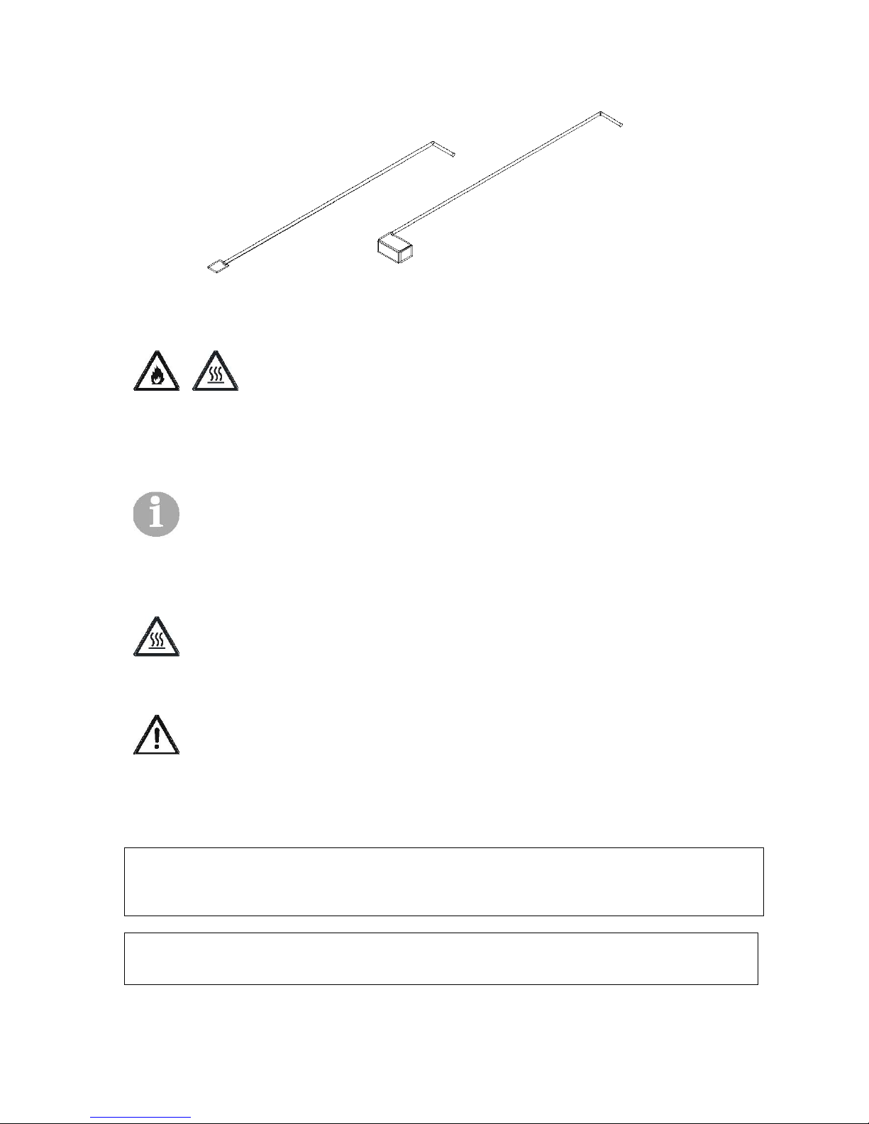
Figure 10. Boiler Cleaning Kit
When cleaning the furnace of ashes and soot deposits by vacuum cleaning, the ash has to be
cooled, i.e. to have the room temperature, in order to avoid the risk of the combustion of the
vacuum cleaner with which we suck up the ashes.
When removing the front part of the fire clay in order to clean the furnace there is the risk of
burns. Fire clay is hot and it is necessary to leave enough time for cooling down.
The amount of the ashes in the furnace depends in many aspects on the pellet quality. If the
pellet is of the better quality, the need for cleaning will be less frequent. The pellet of the better
quality leaves less dust.
When cleaning chimney, flue pipe and the elbow there is a risk of burns because these
surfaces may have the temperature up to 150 °C during the operating regime. It is necessary to
leave enough time for cooling down.
When performing the cleaning works, there is a risk of carbon monoxide poisoning, if the
combustion process is not over and the clearing process is performed carelessly. In this case,
carbon monoxide is emitted through openings on the boiler (i.e. open doors, removed flue pipe,
or the elbow). Never leave the boiler door open longer than it is necessary.
NOTE
In order to extend the life expectancy of the heater, which ignites the pellet, it is
necessary during the cleaning to pay attention to the output of the heater in the furnace.
The opening for hot air must be free of the ashes (mustn't be congested).
NOTE
After the heating season, you must thoroughly clean the boiler, thus the boiler
exploitation is increased.
Page 32

User guide BIOTOPLING-3BT
________________________________________________________________________________________
_____________________________________________________________________________
-- 32 --
TOPLING JUNE 2012 3BT 25-50 kW
6. Possible problems in functioning
Table 7. Possible problems during the operation – spreadsheet.
Problem
Cause Elimination
The boiler
operates, but it
cannot achieve the
set temperature
1. The boiler is dirty
1.Clean the boiler
2.There is no enough fuel in the
boiler
2.Inrease the dosing of feeder
3.Fire clay elements are not
well placed into the furnace
3.Properly place the fire clay elements into the
furnace
Boiler is getting
wet
Flue gas condensation
1. It is installed the excessive force of radiators.
The boiler does not have enough power.
Replace the boiler with a boiler of a higher
power or adjust the number of radiators with the
boiler power.
The boiler is damaged It is necessary to weld the boiler. Only the
authorized service technician or the producer
can perform that.
The smoke returns
from the boiler
The chimney, chimney pipe or
convective beam are dirty
Clean
Too small opening of the
chimney
Adjust cross section of the chimney with the
boiler power
Boiler does not
operate
There is no voltage
1.Check the plug
2.Check the fuse of the home installation
Boiler achieves the
set
temperature, but
the radiators do
not heat
The pump does not operates,
but there is a voltage on it (the
pump is not delivered with the
boiler)
The pump is bunt up,. It is necessary to
unscrew the cap of the pump and to try to start it
with the screwdriver
The pump has no voltage Check the fuse of the pump
The fan does not
work
1.Fuse blown
2.Foreign body in the van
1. Replace the fuse
2.Check whether fan functions without any
obstacles
The pellet cannot
be ignited
1. No voltage on the heater
2. Faulty heater
3. The furnace is dirty
4. There is no pellet in the
storage
5. Time for ignition not correctly
selected
6. Faulty fan
7. Faulty pellet dosing system
8. Faulty flue gas probe
1.Check the fuse
2. Change the heater
3. Clean the furnace
4. Refuel the tank with the pellet
5. Set the correct time for Fire
6. Solve a problem on the fan
7.Repair the defect at snail pellets or gear
reducer
8. Replace the probes
There is no dosing
of pellets into the
firebox
1. No power on gear reducer
2. Foreign body in the dosing
tube
3. Too moist pellet
4. Faulty engine
1. Check the fuse
2. Clean the tank and dosing pipe
3. Use the pellet of a good quality
4. Replace the engine
Page 33
User guide BIOTOPLING-3BT
________________________________________________________________________________________
_____________________________________________________________________________
-- 33 --
TOPLING JUNE 2012 3BT 25-50 kW
7.1 When can we expect the occurrence of
fire in pellet storage
In the case if the boiler is connected to an inadequate chimney (insufficient height, insufficient
cross-section of the chimney, reduced cross-section due to dirt, very dirty boiler) there is a risk
that fire returns from the firebox into a dosing pipe and pellet storage.
The boiler is equipped with a double protection from the fire in the pellet storage, as follows:
- One part of the air for combustion is discharged into the pellet dosing pipe and
prevents the penetration of the flame in the storage. This air is constantly present
during the boiler functioning.
- In the case of the chimney of a really bad quality mentioned air may be insufficient to
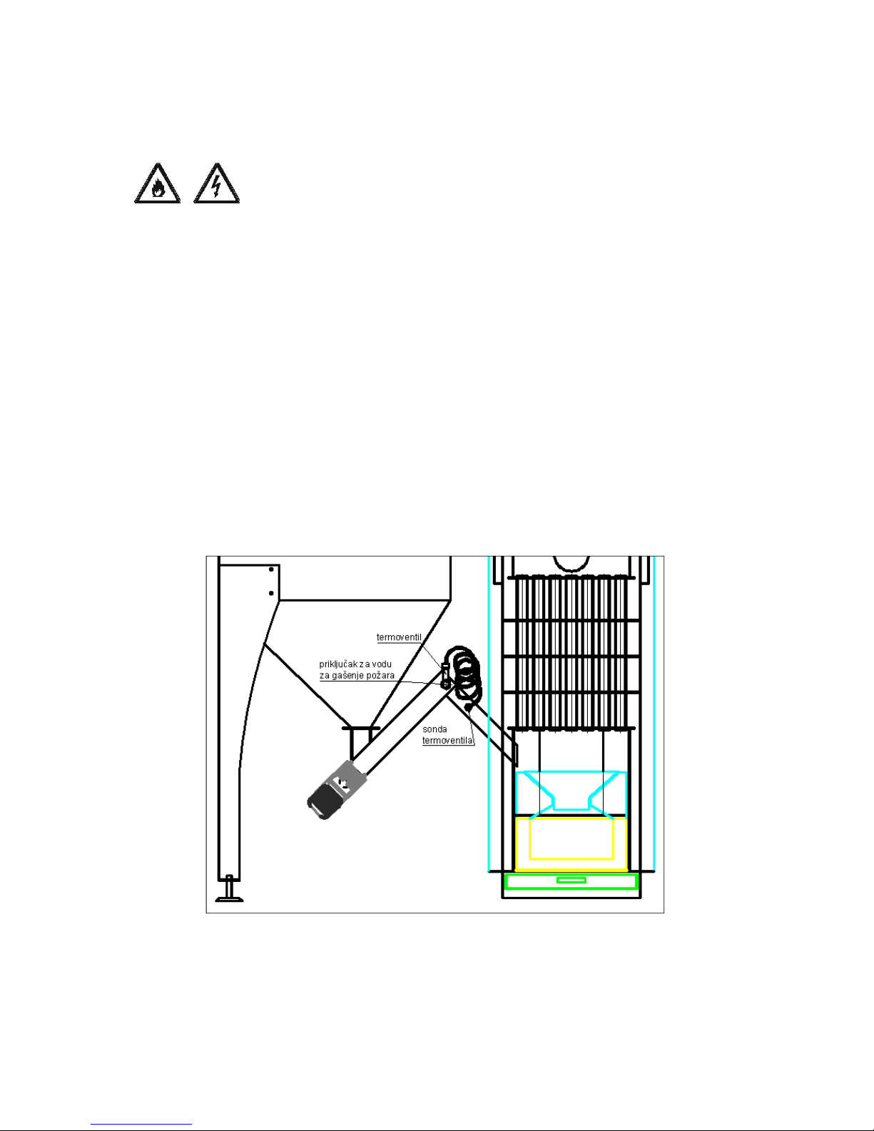
prevent entrance of the air into the storage. Thermo valve activates then (see Figure
11) which opens on a temperature of 95°C and enables the supply of water which
through the system on thermo valve partly enters the screw conveyor and the dosing
pipe, and partly in the pellet screw conveyor and thus performs fire fighting. Thermo
valve together with its probe (see Figure 11) is factory installed into the boiler. The
obligation of the customer is to provide a water supply for fire fighting on the thermo
valve connection (connection is ½'') (see Figure 11).
THE CUSTOMER'S OBLIGATION IS TO COMPLY WITH THE INSTRUCTIONS OF THE
MANUFACTURER ABOUT THE QUALITY AND CHIMNEY DIMENSIONS (SEE FIGURE 5
AND 6). YOU MUST ALSO FOLLOW THE GUIDELINES FOR BOILER MAINTAINING (SEE
CHAPTER 6) IN CASE OF FIRE WHOSE CAUSE IS INADEQUATE OR DIRTY CHIMNEY
FURNACE, THE MANUFACTURER IS NOT RESPONSIBLE FOR THE DAMAGE.
Figure 11. Connection site of thermo valve with the pellet dosing system (PP set)
Page 34

User guide BIOTOPLING-3BT
________________________________________________________________________________________
_____________________________________________________________________________
-- 34 --
TOPLING JUNE 2012 3BT 25-50 kW
7.2 Which steps are to be taken when
thermal valve gets activated and lets the
water into the pellet dosing system
- It is necessary to disconnect the boiler form the electric power supply
- Take out the screw feeder form the tube
- Remove the wet pellet from the storage and dosing system
- Put the screw feeder and gear reducer back in their place
- Make sure that the remaining water do not cause the short circuits.
Therefore, it is necessary to remove the remaining water and dry the
wet parts of the boiler
- Provide electricity supply to the boiler
If the wet pellet remains in the dosing system, the conveyor may be blocked and winding of the
motor redactor may be blown. The producer of the boiler is not responsible for the damage.
Page 35

User guide BIOTOPLING-3BT
________________________________________________________________________________________
_____________________________________________________________________________
-- 35 --
TOPLING JUNE 2012 3BT 25-50 kW
7. THE FIRST COMMISSIONING
The first putting into operation of the 3BT boiler should be done by a specialized person of
Topling Company or an authorized service technician.
Besides putting the boiler into operation, an authorized person should inform a customer about
operation of boiler, its use and about maintenance and cleaning of the boiler.
The boiler should be put into operation by a qualified person. If unqualified person performs the
putting into operation, there is the possibility of damage and complete destruction of the boiler.
Improper handling can cause injuries.
8.1. Requirements for successful
commissioning
The following conditions must be met before starting safe putting into operation of the boiler:
TURN OFF THE ELECTRICAL SUPPLY TO THE BOILER
• Is the main swath for power supply to boiler turned off?
CHECK MECHANICAL COMPONENTS OF THE BOILER
• Are all mechanical components properly implemented into the boiler?
• Are all mechanical components properly and firmly fixed to each other?
• Is the boiler furnace for pellet combustion properly implemented in the boiler?
• Is the fan properly implemented?
• Are the chamotte blocks properly implemented in the boiler furnace?
CHECKING OF PIPING AND INSTALLED COMPONENTS
• Is the circulation pump properly implemented?
• Is the safety valve properly implemented?
CHECK ALL ELECTRICAL CONNECTIONS
Danger!
Risk of electric shock.
• Are all electric components (motor reductor, fan, controller) properly
implemented?
• Is the main power cord connected properly?
• Is the cable which connects display with control unit connected properly?
• Are the unused connectors for connecting input and output devices properly
protected?
• Are the earth grounds connected to the boiler body?
Page 36

User guide BIOTOPLING-3BT
________________________________________________________________________________________
_____________________________________________________________________________
-- 36 --
TOPLING JUNE 2012 3BT 25-50 kW
8. DISPOSAL AFTER END OF LIFE
9.1. Dismantling boiler
Danger!
The boiler must be disassembled by a professional.
Material damage and injury can occur if an unprofessional person disassembles the
boiler.
Dismantling of the boiler from central heating installations should be performed at
following stages:
1. Switch off the boiler, i.e. stop the boiler operation
2. Leave enough time for boiler and the boiler mechanism to burn the remains of
pellets
3. Separate the boiler from the power supply
4. Isolate boiler heating system by closing the valve, and then drain the water from
the boiler
5. Demount pellet storage
6. Demount boiler panelling
7. Separate mineral wool from the boiler
9.2. Disposal of boiler
The following components of the boiler are made of steel and must be handed to the
centre for collection of secondary raw materials.
• The body of the boiler,
• Plating boiler
• pellet storage
• Screw conveyor
• Motor reductor
• Boiler furnace.
Electrical components are necessary to be collected and handed to the centre for
collection of secondary raw materials.
Glass Braid (located on the door of the boiler), mineral wool and plastic parts, must be
separated and handed to the centre for collection of secondary raw materials.
Do not throw the boiler components in the dumpster.
Page 37

User guide BIOTOPLING-3BT
________________________________________________________________________________________
_____________________________________________________________________________
-- 37 --
TOPLING JUNE 2012 3BT 25-50 kW
9. GUARATEE
10.1. Period of guarantee
The warranty period for boiler is two years.
10.2. Terms of guarantee
• The boiler must be put into the operation by the TOPLING company or our
authorized service technician.
• The boiler must be used in the accordance with recommendations written in this
user guide.
• The quality of pellet must be in the compliance with recommendations written in
this user guide.
10.3. When the guarantee is not
recognized
• The warranty is not valid if the damage is the result of the improper use
• If the installation and putting into operation is performed by an unauthorized
persons
• f the service is performed by an unauthorized persons
• If the boiler is not maintained in the compliance with the recommendations
written in this guide
• If the damage is caused by natural disasters (earthquakes, floods, fires,
lightning, etc.)
• If the damage is cased because of inadequate power supply (too high or too
low voltage).
• If the unoriginal spare parts are installed
• If the failure occur because of the improper installations (circulation pump,
expansion, etc.), i.e. of the parts which are not the constituent part of the boiler,
but are the condition for the functioning of the boiler.
• Because of improperly or incompletely filled Warranty sheet.
 Loading...