

Page 1

INSTRUCTION MANUAL
TP-S1016MDR
Digital Video Recorder
Page 2
Safety Precautions
CAUTION
DO NOT REMOVE COVER. NO USER SERVICEABLE PARTS INSIDE.
REFER SERVICING TO QUALIFIED SERVICE PERS ONNE L.
WARNING
TO REDUCE RISK OF FIRE OR E LECTRIC SHOCK,
DO NOT EXPOSE THIS APPLIANCE TO RAIN OR MOISTURE
Safety Precautions
Refer all work related to the installation of this product to qualified service
personnel or system installers.
Do not block the ventilation opening or slots on the cover.
.
Do not drop metallic parts through slots.This could permanently damage
the appliance. Turn the power off immediately and contact qualified service
personnel for service.
Do not attempt to disassemble the appliance.To prevent electric shock,
do not remove screws or covers. There are no user-serviceable parts
inside. Contact qualified service personnel for maintenance. Handle the
appliance with care. Do not strike or shake, as this may damage the
appliance.
Do not expose the appliance to water or moisture, nor try to operate it in
wet areas. Do take immediate action if the appliance becomes wet.
Turn the power off and refer servicing to qualified service personnel.
Moisture may damage the appliance and also cause electric shock.
Do not use strong or abrasive detergents when cleaning the appliance
body. Use a dry cloth to clean the appliance when it is dirty. When the
dirt is hard to remove,use a mild detergent and wipe gently.
Do not overload outlets and extension cords as this may result in a risk of
fire or electric shock.
Do not operate the appliance beyond its specified temperature, humidity
or power source ratings. Do not use the appliance in an extreme
environment where high temperature or high humidity exists. Use the
appliance at temperat ur e wit hin 0
The input power source for this appliance is AC100~240V
o
C ~ +40oC and a humidity below 90%.
Page 3

Safety Precautions
Safety Precautions
The lightning flash with an arrowhead symbol, within an
equilateral triangle, is intended to alert the user to the
presence of uninsulated ” dangerous voltage” within the
product’s enclosure that may be of sufficient magnitude to
constitute a risk of electric shock to persons
The exclamation point within an equilateral triangle is
intended to alert the user to presence of important
operating and maintenance(servicing)instructions in the
literature accompanying the appliance.
Warning :
To prevent fire or shock hazard, do not expose units not
specifically designed for outdoor use to rain or moisture.
Attention:
Installation should be performed by qualified service personnel
only in accordance with the National Electrical Code or
applicable local codes.
Warning:
Electrostatic-sensitive device. Use proper
CMOS/MOSFET handing precautions to avoid
electrostatic discharge.
UNPACKING
Unpack carefully.
This is electronic equipment and should be
handled carefully.
Check to ensure that the following items are included;
•1. Digital Video Recorder unit
•2. User’s manual
•3. Power Cord
•4. HDD tray key and screws
•5 Alarm I/O board
If an item appears to have been damaged in shipment,
replace it properly in its carton and notify the shipper.
Do not place on uneven or unstable work surfaces.
Seek servicing if the casing.
Power Disconnect:
Units with or without ON-OFF switches have power
supplied to the unit whenever the power code is inserted
into the power source; however, the unit is operational
only when the ON-OFF switch is in the ON position.
The power cord is the main power disconnect for all units.
AC100~240V Power Cords
Note:
This is a class A product. In a domestic environment this product may cause radio interference
In which case the user may be required to take adequate measures.
Note:
Before installing and using this unit, please read this manual carefully. Be sure to keep it handy for later
reference.
The information in this manual was current when published. The manufacturer reserves the right to revise
and improve its products. All specifications are therefore subject to change without notice.
Page 4
Important Safeguards
Important Safeguards
Read Instruction---All the safety and operating instructions should be read before the init is operated
Retain Instructions---The safety and operating instructions should be retained for future reference.
Heed Warnings—All warnings on the unit and in the operating instructions should be adhered to.
Follow Instructions—All operating and use instructions should be followed
Cleaning—Unplug the unit from the outlet before cleaning. Do not use liquid cleaners or aerosol
cleaners. Use a damp cloth for cleaning
Attachments—Do not use attachment not recommended by the product manufacturer as they may
cause hazards.
Water and Moisture—Do not use this unit near water-for example, near a bath tub, wash bowl,
kitchen sink, or laundry tub, in a wet basement, near a swimming pool, in an
unprotected outdoor installation, or any area which is classified as a wet location.
Servicing—Do not attempt to service this unit yourself as opening or removing covers may expose
you to dangerous voltage or other hazards. Refer all servicing to qualified service personnel.
Power Cord Protection—Power supply cords should be routed so that they are not likely to be walked
on or pinched by items placed upon or against them, playing particular
attention to cords and plugs, convenience receptacles, and the point where
they exit from the appliance.
Object and Liquid Entry—Never push objects of any kind into this unit through openings as they may
touch dangerous voltage points or short-out parts that could result in a fire or
electric shock, Never spill liquid of any kind on the unit.
Page 5

Table of Contents
1. Product Overview…………………………………….………………..….…..…..Page 2
1.1 Main features……………………………………………………………….….....…..….2
1.2 Specifications…………………………………………………… ……… . …..……… .. 3~4
2. Back panel connections……………………………………………….........………5~6
3. Front panel keypads…………………………………….…………….….………..…7~8
4. Operation…………………………………………………………..………………………..9
4.1 Monitor Display………………………………………………….……… 10~12
5 Menu flow
5.1 Time/Data setting menu………………………………………...……………….…13~15
5.2 Camera setting
5.3 Record setting
5.4 Alarm setting menu………..……………………..………………………………....20~21
5.5 Motion setting men u………..……………………..……………………………….. 22~24
5.6 Vloss setting menu…………………………………..………………………………….2 5
5.7 Network setting menu………………………………..……………………………..26~33
5.8 Sehedule setting menu… …………………….. …………………………………..……34
5.9 Disk setting menu……………………………………………………………………..…35
5.10 Control setting menu…………………………………………………………...……...36
5.11 Warning setting menu…………… ………… ……… ………… ……… ……… .. .. . 3 7~40
5.12 System setting menu…………………………………………………………......41~42
6. Recording………………………………………………………………..….....………...…43
6.1 Instant recording…………………… ………… ……… ……… .…… …… ……. ……... .. 4 3
6.2 Schedule recording………………………………………………….………………..…44
6.3 Event recording……………………………………………………………………...44~45
7. Playing back…………………………………………………………….……….....…..…46
7.1 Normal playback…………………………………………………….……………...46~47
7.2 Search playback……………………………………… ………… .… ……. .…… .... . 4 8~4 9
8. Copy To A Video File……………………………………………….……………...50~52
menu……………………………………….…………………. .. . .. 1 6~1 7
menu………………………………………...………… … ….… …. . 1 8~1 9
9. Call…………………………..................................................................53
10. Remote Viewer………………………………………………………….…….54~63
Appendix-A :RS232 specifications………………..…………………….…..…64~68
Appendix-B :RS485 specifications………....…….………...………………………69
Appendix-C :Alarm I/O Assignment……………………...……………………....70
Appendix-D :Lapse Mode Recording Table….........………………..……....61
Appendix-E :DDNS………………………….....................................................62
Page 6

1. PRODUCT INTRODUCTION
The Digital Video Recorder is the industry’s first full-featured digital video recorder
designed specifically for use in security industry. The Digital Video Recorder
incorporates all the benefits of digital video recording, is simple to install, and operates
just like a VCR. Highly efficient compression technology and superior resolution of
recorded images make the Digital Video Recorder stand out from the competition as the
best choice for security surveillance.
1.1 FEATURES
Multiplex operation for doing back-up, recording, playback and remote playback at
the same time
Buitl-in MPEG4 Compression technology for minimum size of video storage
Dual NTSC/PAL system through auto detection of Camera 1 input
Remote live viewing, recording, playback and controlling via Ethernet through LAN
network and internet browser
Auto time synchronization with global NTP server through internet
Fast and large image backup via USB Pen Driver
Two HDD storage (one built-in type & one hot-swapable tray)
Each camera can be configured by different resolution, quality and IPS
Motion detection by individual or all cameras in different detection areas and
sensitivities
Easy operation by IR Remote Controller(optional) and Jog Shuttle simply just as
a VCR
Alarm-triggered or Motion Detection Event alert by emails
Various recording speed up to 50/60 fields (NTSC/PAL)
▓ Quick search by date/time, alarm events(Motion, Video Loss, Alarm)
▓ On-screen setup menu with multi-language support
▓ Multi-level password protection
▓ RS-232 & RS485 communication port
Audio recording capability
2
Page 7

1.2 SPECIFICATIONS
Video Format NTSC/EIA or PAL/CCIR
Video Input 16 camera inputs (BNC), 1Vp-p/75ohm
1 BNC video out (1Vp-p/75ohm) for Main Monitor
Video Output
1 BNC video out (1Vp-p/75ohm) for CALL Monitor
16 video out (1Vp-p/75ohm) for Looping
1 VGA video out (optional)
Video Compression MPEG4
720x240, 720x480 or 360x240 for NTSC
Recording Resolution
720x288, 720x576 or 360x288 for PAL
Full, PIP, 4, 7, 9,10,13,16 and 2x2 Zoom for Live
Video Display
Viewing and Playback
720x240, 720x480 or 360x240 for NTSC
Display Resolution
720x288, 720x576 or 360x288 for PAL
Video Pause Yes
Alarm Inputs 16 Alarm Inputs
Alarm Ou tpu t s 2 Alarm Outputs
Two 3.5” IDE Type Hard Disks for storage one
Hard Disk Storage
Hot-swappable type one built-in type
Recording Rate Up to 60/50 Images per second for NTSC/PAL
Continue, Time-lapse, Sched ule,
Recording Mode
Event recording (Motion and Alarm)
Playback Rate Up to 60/50 Images per second for NTSC/PAL
Playback Search By Date/Time or Event (Motion, Video Loss, Alarm)
Yes, with MULTIPLE configurable detection areas &
Motion Detection
sensitivity
Video Loss Detection Yes
Event Log Yes
User Interface User-friendly Menu Driven
Setup On screen display setup
Front panel keypad with Shuttle/Jog, Keyboard
User Input Device
(optional)
Built-in real time clock and Auto Time
Timer
Synchronization with global NTP server thro ugh
Watch Dog Timer Yes
Internet
3
Page 8

Title
Ethernet
Archive
RS-232
RS-485
Audio
Power Rate
Dimension
Weight
Operating
Temperature
Remote Controlle r
12-chara cters title gene rator for each camera
RJ45 connectors for network communication
Compact Flash Slot and USB for archiving
and Archive through Wireless transmission (Optional)
9-pin female connector for local communication
for Keyboard connection
2 mono (MIC) inputs, 2 mono (SPEAKER) outputs
DC 12V/DC 24V
Half size: 320 mm (L) x 215mm (W) x 100mm (H)
Mobile : 320.8mm (L) x 215mm (W) x 109.9mm(H)
4.85 KG
o
0
C ~ +50oC
IR Remote Con tro lle r
IR Remote Controller with Extension Wire(optional)
4
Page 9
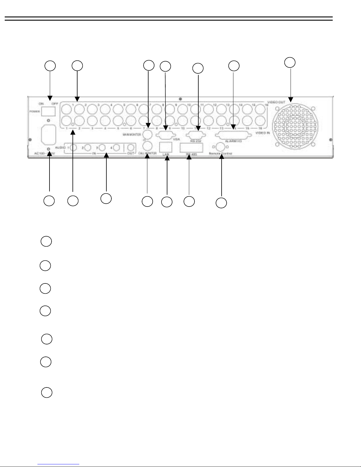
2. Back Panel Connections
Back Panel Connections
1 8
2 3
4
12
6
14
5
9
11
13
7
10
1
ON/OFF: Main on/off switch.
2
AC100~240V power socket.
3
VIDEO IN: The BNC connectors of video input enables the system to receive the
signals from each camera through the 75 ohm coaxial cables.
4
VIDEO OUT: Loop through video outputs for each input channel.
(TP-S104MDR: 1 ~ 4 only )
5
CALL MONITOR: BNC-socket Call (Spot) Monitor, composite signal. (Full screen display only)
6
MAIN MONITOR: BNC-socket main monitor, composite signal. Main monitor provides
Full screen, Multi-screen, Setup.
Remote Control: Remote control port provides you an extension wire with an IR receiver instead
7
of the IR receiver on the front panel.
Note: The IR receiver extension line (10m) must be purchased separately.
5
Page 10

Back Panel Connections
8
9
10
Alarm Input
ALM-INPUT: Normal open or normal close type alarm signal inputs.
The Alarm Input can be selected as normal open (N.O.) or normal close (N.C.) input
in the ALARM SETUP MENU. When an alarm occurs, alarm recording will
automatically start.
ALM-OUTPUT: A build-in relay offers 3 nodes which are ALM-COM (common), ALM-NO
(normal open) and ALM-NC (normal close) for external use.
Note: Please check APPENDIX C to see other available alarm input/output functions.
LAN Connector : RJ-45 LAN connector for internal 10MBit LAN interface.
FAN: Cooling fan, do not cover.
11
12
RS485 connector : 2 x RJ-45 connectors for RS-485 remote control, high impedance
Supported are keyboards KS-KBK, KS-KBJ (Optional).
Maximum units in RS-485 network are 32.
Audio IN: Audio input for recording, and it can be set to “YES”or “NO”in the RECORD SETUP
MENU.
Audio OUT: Connect to an audio input of a monitor or other device.
13
RS232 connector : D-Sub 9 pins connector to RS232 ports for remote control.
14
VGA MONITOR: Connect to the monitor that has VGA input. (VGA is an optional device).
6
Page 11
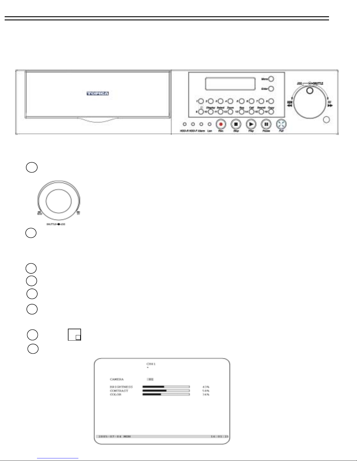
3. Front Panel Keypads
1
SHUTTLE Ring and JOG Dial
Front Panel Keypads
SHUTTLE : In Playback mode, turn the shuttle ring to fast
forward/rewind the picture In Pause mode,
turn the shuttle dial to slow forward/rewind
the picture
JOG : In Pause mode, turn the jog dial to step forward/rewind the Picture.
In Menu mode turn the jog dial to select options.
2
CHANEL KEYS:
.
Press these keys :to display video image in full screen
format, the picture of the corresponding camera will fill the whole screen of the monitor display.
3
MENU: Press this key to enter Setup Menu (Please refer to page 12~29 for details).
4
CALL: Press this key to show picture of assigned camera to desired call monitor.
5
SEQ : Press this key to enter the auto sequential switching mode for main monitor.
ZOOM: Press this key while viewing the full screen image to display X2 zoom-in picture. To move
6
the zooming area, use JOG to move from left to right. Press ENTER for changing vertical /
horizontal movement.
MODE: Switch Full, 4, 7, 9,10,13,16 PIP (picture in picture) multi-screen for Live andPlayback.
7
SELECT: In Full screen mode: press this key to pop-up dialog as below:
8
7
Page 12

Front Panel Keypads
In the screen display setting menu, we define:
(1) CAMERA: The display setting of the current camera.
(2) BRIGHTNESS: The bright percentage of the current camera; from 0% to 100%.
(3) CONTRAST: The contrast percentage of the current camera; from 0% to 100%.
(4) COLOR: The color percentage of the current camera; from 0% to 100%.
The selected item will show in red color bar. Use Jog to increase or decrease the value. Press ENTER to
confirm the setting value and move to next item. After finished setting, press SELECT or MENU key to
save and exit the dialog. Total of 8 channels are adjustable.
Display: Press this key to switch ON/OFF for camera title, date/time and HDD status.
9
Hold this key longer than 2 seconds for displaying the event log list.
10
USB Slot: Insert a USB for archiving video.
11
Hard Disk Trays: 2 x Hard Disk holder one for 3.5”hot-swapable HDD.another for
built-in HDD
12
HDD locks: Turn on HDD power and protection from taking out the HDD without authority.
13
REC: Press this key to start recording.
14
STOP: Press this key to stop recording or playing b a ck.
15
PLAY: Press this key to stat playing back recoded picture (Please refer to page 44 for details).
16
PAUSE: Press this key to pause the playback picture.
17
SEARCH: Press this key to enter the Search Menu (Please refer page 46~47 for details).
18
COPY: Under PAUSE or PLAYBACK, Press this key to start copying still picture or video
stream into (Please refer page 48~49 for details).
19
ENTER: Press this key to enter sub-menu or confirm setup. When there is Alarm, Motion
or Video Loss occurs, press this key for alarm reset. The Event Log Dialog will show on
the display, then follow the instruction to continue.
20
LEDs: LEDs for HDD1, HDD2 , ALARM and LAN access (from left to right).
21
IR Remote Controller receiver
22
LCD Panel: To display Date/Time, Recording/Playback and HDD status.
8
Page 13
4. Operation
(1) Insert a HDD (IDE) for Video Stor age
Insert one or two HDD (3.5” IDE) for Video Storage.
The HDD should be set a s Ca bl e Se le ct .
(Normally the default setting of HDD is Master)
Note: After hard disk case is inserted into the hard disk tray, be sure to turn the tray key
in lock position.Otherwise, HDD will not be det e ct ed .
ATTENTION: Changing HDD’s and switching on HDD’s is not allowed in record mode!
(2) Connect cable for video/ audio input and video/audio out,
The detail connection is described in SYSTEM CONNECTION
(3) Switch Power On
The LCD panel in the front panel will light when you switch on the power.
Operation
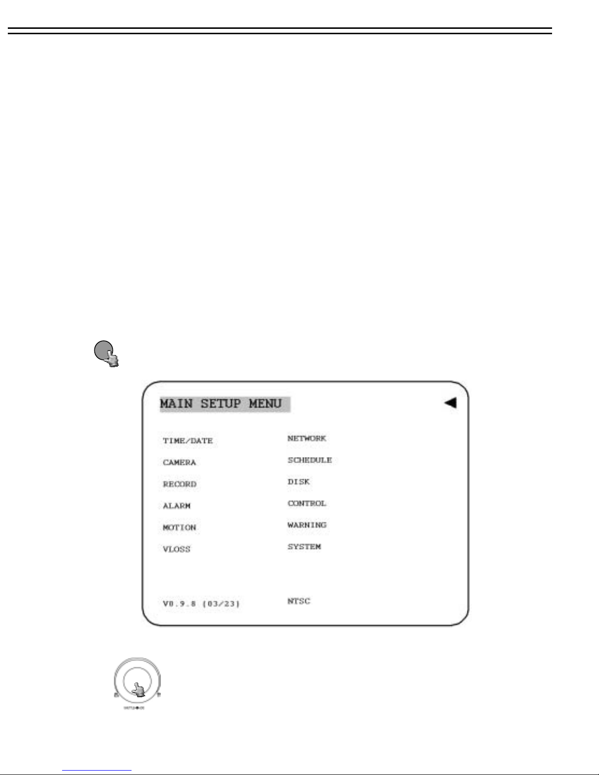
(4) Press MENU key to enter SET UP MENU.
Once inside the main menu you will find there are 14 set up pages as below:
Selected item will be surrounded by a white block.
MENU
(5) Turn the JOG dial clockwise or counter-cl ockwise t o sel e ct th e item,
press ENTER key for detail set up for each item.
(6) Press MENU again to leave the set up menu.
9
Page 14
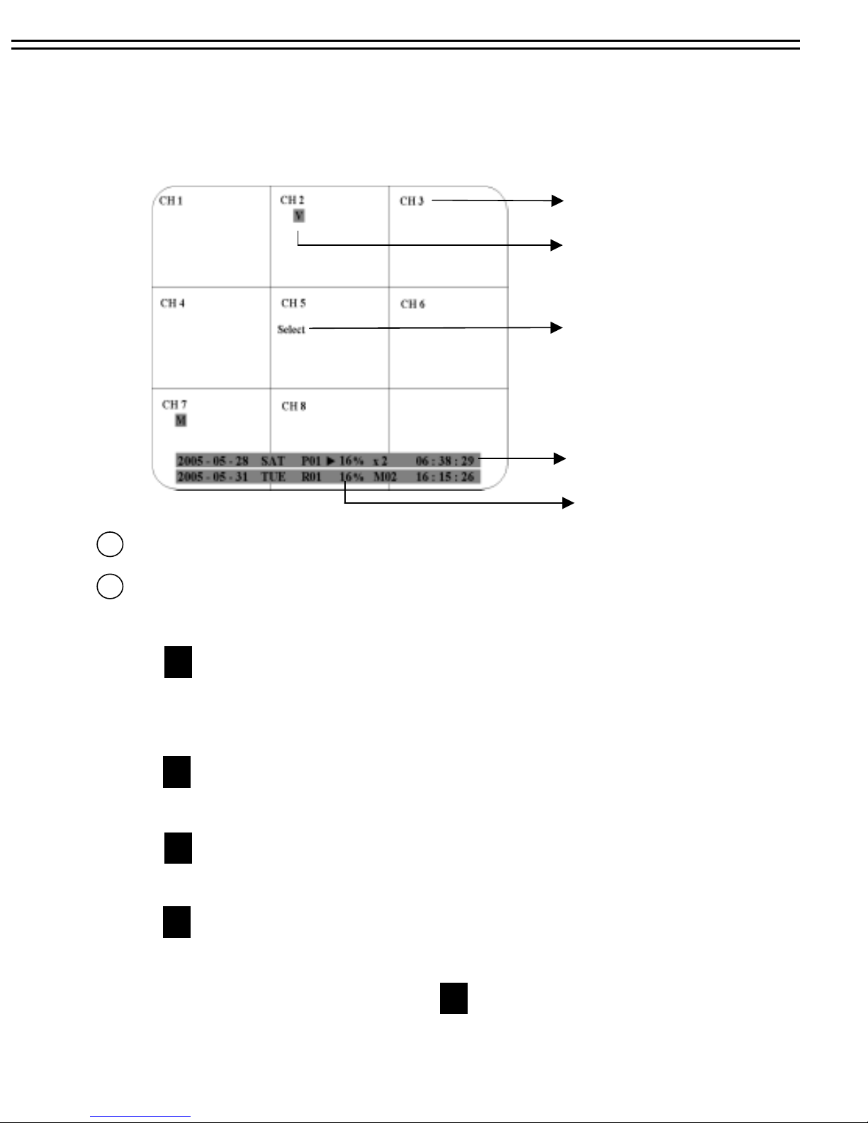
4.1 MONITOR DISPLAY
The status information of the cameras or machine will show up, and be located at different places on the
screen.
1. Channel tag
2. Event sign
3. Select sign
4. Play status bar
5. Record status bar
1
Channel tag: A channel tag indicates the channel name of the screen.
Event sign: Event signals which are small icons with a capital letter and red background show the
2
events on each screen. There are 4 different signals which are
: Alarm event. The alarm place where the camera locates. In order to show the
A
camera video to a corresponding alarm, setting a FOCUS CAMERA in ALARM
SETUP MENU is necessary.
: Motion event. Motion event only shows up when the camera’s MOTION is enabled
M
in MOTION SETUP MENU, and the camera detects a motion.
: Video loss event. Video loss event only shows when the camera’s VLOSS is
V
enabled in VLOSS SETUP MENU, and the camera signal is lost.
: Sequence sign. Sequence sign shows up when the display is in the sequence mode.
S
The sequence display is located on display with a “*” sign in 4, 7, Full screen and PIP
(picture in picture) display mode. The sign will replace “*” sign in the
display when sequence occurs.
S
10
Page 15

3
Select sign: You can assign a camera to a display by pressing SELECT key in life mode. Dial Jog to
move the select sign to the display you would like to change camera, and then press FULL +
channel key to relocate the camera.
4
Play status bar: The play status bar appears in play back mode if you enable a status bar on the screen
(Check page 6, item 9th, DISPLAY). Three parts which are play date, play time and
play status are shown in the play status bar.
Play Date Play Status Play Time
1. Play date: The play date in which the video is recorded.
2. Play status: It shows PAUSE, play speed and reverse play speed.
“PAUSE”, when the video play is paused.
“>” means normal play speed;
“<“ means normal reverse play speed;
“>> x N” means N time fast play speed;
“<< x N” means N time fast reverse play speed.
3. Play time: The play time at which the video is recorded. The time format depends on
the time format setting in the TIME/DATE SETUP MENU.
Record status bar: The record status bar appears when you enable a status bar on the screen (Check
5
page 6, item 9th, DISPLAY). Three parts which are current date, record status (% of space used for
recording) and current time.
Current Date Record Status Event Current Time
11
Page 16

1. Current date: The current date which is set in the TIME/DATE SETUP MENU.
2. Record status: It shows REC and recording hard disk number.
“REC”, it shows when machine is recording.
“R01”, the recording hard disk number. There is only one hard disk available in
this model, so it always shows R01 when recording.
3. Event: The last happened event.
4. Current time: The current time which is set in the TIME/DATE SETUP MENU.
12
Page 17
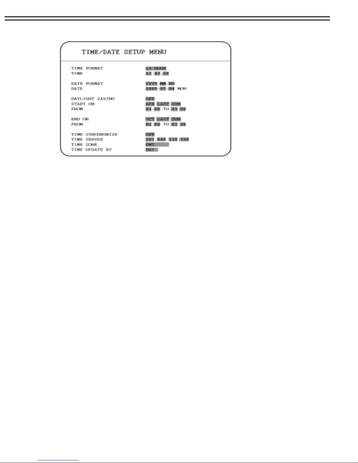
5.1 TIME / DATE SETUP MENU
In the TIME/DATE SETU P MENU, we define :
MENU
(1) TIME FORMAT:
There are two time formats that are 12 HOUR and 24 HOUR to be selected.
(2) TIME: Current time
Hour: 00 ~ 23 (1 ~ 12 if TIME FORMAT is 12 HOUR)
Minute : 00 ~ 59
Second: 00 ~ 59
(3) DATE FORMAT:
There are three date formats which are YYYY-MM-DD, MM-DD-YYYY and DD-MM-
YYYY to be selected.
(4) DATE: Current date
Date: 01~31 Month:01~12 Year: 2000 ~ 2099 Day:Sun~Mon
(5) DAYLIGHT SAVING:
Select “ON”or “OFF” to enable or disable daylight saving time function.
In order to set a daylight saving time zone, you need to disable daylight saving first. Enable the
daylight saving after finish setting the time zone.
(6) START TIME: To set the start time of daylight saving time.
13
Page 18

To set the start month of daylight saving time: Dial the jog to set the start month.
JAN FEB MAR APR MAY JUN
JUL AUG SEP OCT NOV DEC
To set the start week of daylight saving time: Dial the jog to set the start week.
1 ST 2 ND 3 RD 4 TH LAST
To set the start date of daylight saving time: Dial the jog to set the start date.
MENU
SUN MON TUE WED THU SAT
FRI
To set the start time of daylight saving time: To set the start “FROM” time and “TO”time of
daylight saving time.
To set the end month of daylight saving time: Dial the jog to set the end month.
JAN FEB MAR APR MAY JUN
JUL AUG SEP OCT NOV DEC
To set the end week of daylight saving time: Dial the jog to set the end week.
1 ST 2 N D 3 RD 4 TH LAST
To set the end date of daylight saving time: Dial the jog to set the end date.
SUN MON TUE WED THU SAT
FRI
To set the end time of daylight saving time: To set the end “FROM” time and “TO”time of
daylight saving time.
14
Page 19

(8) TIME SYNCHRONIZE:
Select “ON”or “OFF” to enable or disable time synchronize which can let you have correct time
automatically when network is connected.
(9) TIME SERVER:
You can set the time server address where you locate if you connect to network and enable time
synchronize.
(10) TIME ZONE:
You can set the time zone where you locate if you connect to network and enable time
synchronize.
(11) TIME UPDATE BY:
Once you enable the TIME SYNCHRONIZE, you can select the synchronization frequency by:
DAY WEEK MONTH
Turn the JOG dial clockwise or counter-clockwise to select the options.
Press ENTER key to confirm the option and move to next column.
ENTER
Press MENU key to return to Main Menu, press again to leave Set up Menu.
MENU
15
Page 20
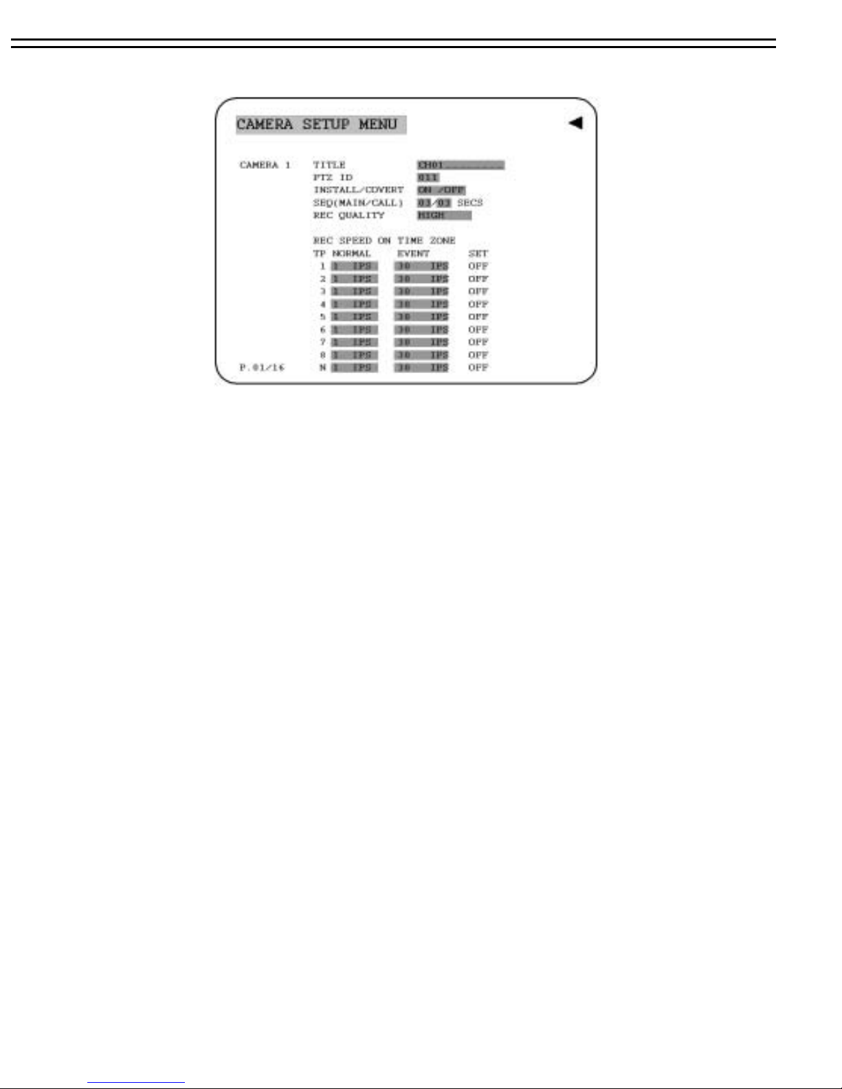
5.2 CAMERA SETUP MENU
In the CAMERA SETUP MENU, we define :
(1) TITLE:
The title setting allows you to assign a title to each camera input.
Titling with 12 characters is supported in each channel.
The available alphanumeric characters are:
0,1,2,3,4,5,6,7,8,9,
A,B,C,D,E,F,G,H,I,J,K,L,M,N,O,P,Q,R,S,T,U,V,W,X,Y,Z,
( ) . , + - / and an empty space.
(2) PTZ ID: Select PTZ ID from 001~255 or OFF. The default value is 10+N where N is camera’s
number.
(3) INSTALL/COVERT: For installation of camera; select “ON” to enable a camera, and “OFF” to
disable it. Please make sure to stop recording before making change of INSTALL. For covert, select
“ON” to cover a camera, and disable the screen in live mode to show up. However, the image is
recorded, and can be played back by user who has playback right. The covert channels will not show
up on the sequence mode.
(4) SEQ(MAIN/CALL): Setup a retention period for sequences.
16
Page 21

(5) REC QUALITY: Select an image quality for recording. Normal record image quality and
event record image quality can be set individually. There are six different qualities available.
A higher image quality needs more HDD space. To change this, simply use the Jog Dial on
the DVR. Press the Enter key to make your selection. The theory space needed per second lists
below
SUPERIOR
HIGH
STANDARD
BASIC
LOW
LOWER
: 10 K /sec
: 11 K /sec
: 13 K /sec
: 15 K /sec
: 19 K /sec
: 24 K /sec
(7) REC SPEED ON TIME ZONE:
SCH: Scheduled recording time 1~16 which can be set in the SCHEDULE SETUP MENU.
The Schedule N in the bottom is normal recording time.
NORMAL: Normal record speed (Images per second) up to 30 IPS.
to the maximum recording speed by calculating the total installed cameras that
have enabled in the CAMERA SETUP MENU.
EVENT : Event record speed (Images per second) up to 30 IPS or “OFF”.
Note: In order to validate a new record speed, you need to disable all record actions before
setting up.
SET: Set “ON” when using schedule recording.
Set “OFF” when not using schedule recording.
Note: The status of SET can only be changed in the SCHEDULE SETUP MENU.
17
Page 22
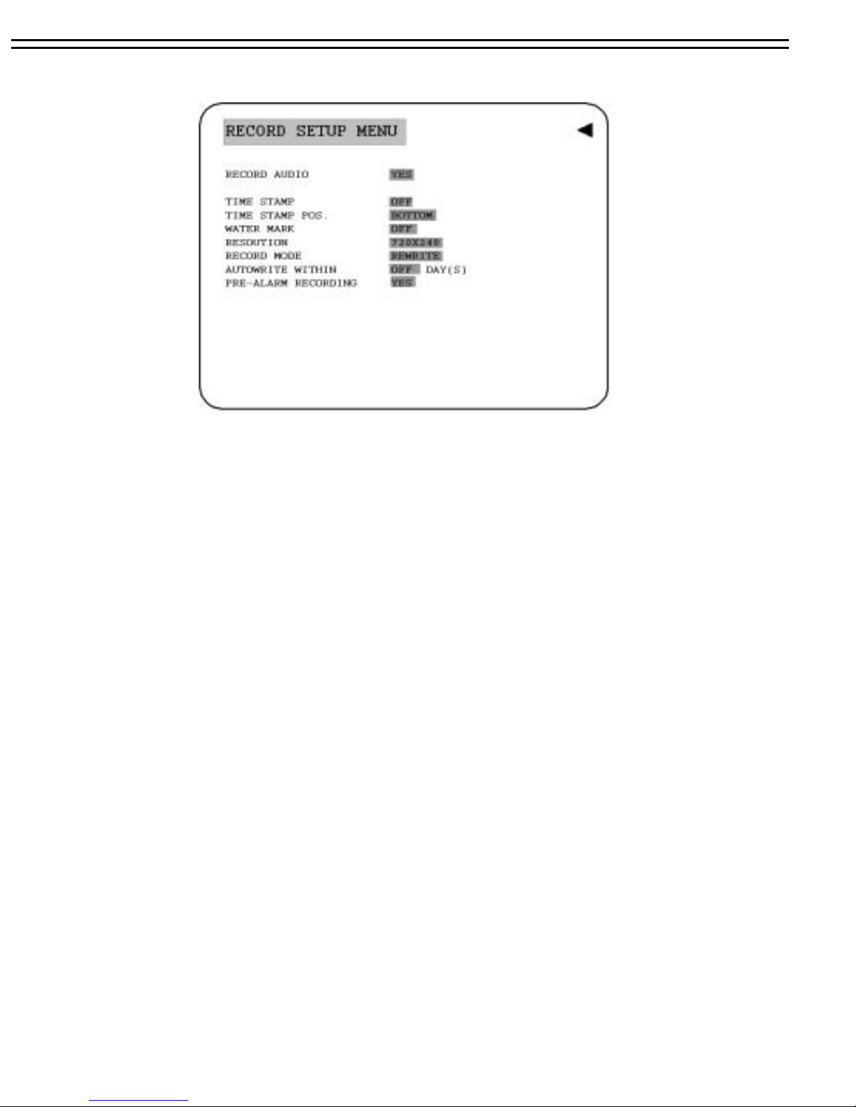
5.3 RECORD SETUP MENU
In the RECORD SETUP MENU, we define :
(1) RECORD AUDIO:
YES: Audio will be recorded when machine is recording.
NO: Audio will not be recorded when machine is recording.
(2) TIME STEMP:
ON: The time stamp will show on the video and picture when recording.
OFF: The time stamp will not show on the video and picture when recording.
(3) TIME STAMP POS. :
BOTTOM: The time stamp will show on the bottom.
TOP: The time stamp will show on the top.
(4) WATER MARK :
ON: Shows a water mark on the picture when copying image to CF card or USB flash memory.
OFF: This erases the water mark on the picture when copying image to CF card or USB flash
memory.
(5) RESOLUTION:
Please select the resolution from 720x480, 720x240 and 360x240. The default value is 720x240.
18
Page 23

(6) RECORD MODE:
REWRITE: Continue recording. Disk will be overwritten if it is full.
STOP: Stop recording when disk is full.
(7)AUTOWRITE WITHIN:
You can set DVR autowrite day, so that DVR will autowrite after the day number you set. If you do not wish to
use this function, please set it OFF.
(8)PRE-ALARM RECORDING:
Select “YES” to enable pre-alarm recording function. Select “NO” to disable pre-alarm recording function.
19
Page 24
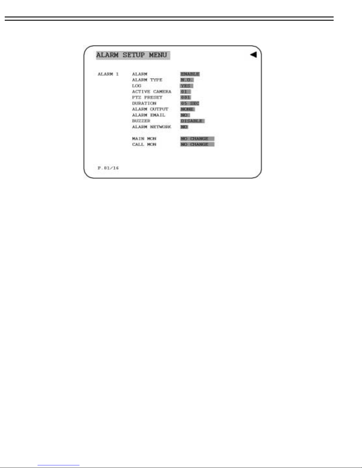
5.4 ALARM SETTING MENU
MENU
In the ALARM SETUP MENU, we define :
(1) ALARM:
ENABLE: Enable alarm detection.
DISABLE: Disable alarm detection.
(2) ALARM TYPE:
N. O. : Normal Open alarm.
N. C. : Normal Close alarm.
N.O. Trans.: When the alarm is triggered, buzzer starts to function no matter how long is the alarm
duration set until you set it back to N.O.
N.C. Trans.: When the alarm is triggered, buzzer starts to function no matter how long is the alarm
duration set until you set it back to N.C.
(3)LOG:
YES: Select YES if you wish to record Alarm Events in the Log.
NO: Select NO if you do not wish to record Alarm Events in the Log
(4) ACTIVE CAMERA:
Active camera setting, from camera 01~08. You can set the camera which corresponds to the
place where the alarm is located.
Note: The recording camera number in an event depends on the alarm number, and the active camera
images will not be recorded. Example: You assign camera 3 as the active c amera to alarm 1.
When the alarm 1 is triggered, camera 3 will be displayed and camera 1 will be recorded.
20
Page 25

(5) PTZ PRESET:
Select PTZ PRESET from “001” to “255”, so that when Alarm occurs, speed dome will turn to this
preset position for event recording. This function improves surveillance quality o f an alarm event. If
you wis disable this function, please simply select “OFF”.
(6) DURATION:
Buzzer noise and event record duration of an alarm, from 1 sec to 99 seconds. The default value is
5 seconds.
(7) ALARM OUTPUT:
The setting of alarms which are NONE and 1, where 1 me ans the alarm is enabled.
(8) ALARM EMAIL:
Select “YES” for sending an email when alarm occurs. The email address can be set in the
NETWORK SETUP MENU.
(9) BUZZER: Alarm buzzer. ( The Default is on )
ENABLE: To enable an alarm buzzer.
DISABLE: To disable an alarm buzzer.
(10) ALARM NETWORK:
YES: Enable alarm network.
NO: Disable alarm network.
(11) MAIN MON: Display on a main monitor when an alarm occurs.
NO CHANGE: Nothing ch anges on the display in the main monitor when an alarm occurs.
FULLSCREEN: A full screen will pop up when an al arm occurs.
(12) CALL MON: Display on a call monitor when an alarm occurs.
NO CHANGE: Nothing ch anges on the display in the call monitor when an alarm occurs.
SEQUENCE: Display in the sequence mode when an alarm occurs.
ACTIVE CAMERA: Display the active camera in full screen mode to the call monitor.
21
Page 26

5.5 MOTION SETUP MENU
In the MOTION SETUP MENU, we define :
(1) MOTION:
ENABLE: Enable motion detection.
DISABLE: Disable motion detection.
Note: Motion only works in live and playback modes. It is invalid when you are setting menus.
(2) SENSITIVITY:
The sensitivity allows users to adjust to a suitable motion detection sensitivity. There are 10
sensitivities available; level 1 is the lowest, and level 10 is the highest sensitivity.
(3)LOG:
YES: Select YES if you wish to record Motion Events in the Log.
NO: Select NO if you do not wish to record Motion Events in the Log
.
(4) DURATION:
The amount of time a motion event will record - from 1 sec to 99 seconds. The default value is
seconds. To change this, simply use the Jog Dial on the DVR. Press the Enter key to make your
selection.
(5) ALARM OUTPUT:
The setting of alarms which are NONE and 1, where 1 me ans the alarm is enabled.
22
Page 27

(6) ALARM EMAIL :
YES: Send an email when an alarm occurs
NO: Do not send an email / Disable alarm network when an alarm occurs.
The email address can be set in the NETWORK SETUP MENU.
(7)ALARM NETWORK
:
YES: Enable alarm network when an alarm occurs
NO: Disable alarm network when an alarm occurs
(8) BUZZER: Motion buzzer.
ENABLE: To enable a motion buzzer.
DISABLE: To disable a motion buzzer.
(9) MAIN MON: Display on a main monitor when a motion occurs.
NO CHANGE: Nothing ch anges on the display in the main monitor when a motion occurs.
FULLSCREEN: A full screen pops up when a motion occurs.
(10) CALL MON: Display on a call monitor when a motion occurs.
NO CHANGE: Nothing changes on the display in the call monitor when a motion occurs.
SEQUENCE: Display in the sequence mode when a motion occurs.
ACTIVE CAMERA: Display the active camera in full screen mode to the call monitor.
23
Page 28

(11) EDIT MULTIPLE MOTION AREA
Enter a desired channel, and press SELECT to edit a motion area. Please make sure that
MOTION is set as “Enable” before entering the motion detection area.
In the motion edit mode:
The default motion area of each camera is
entire screen in light green.
Press COPY to start to set an area.
Then press SEARCH to end and enable the
area, or press PAUSE to end and disable
the area.
Dial JOG to select a horizontal or
a vertical area, and press ENTER
to switch a horizontal or vertical
area.
Press MENU to quit the motion area edit.
To test a motion area: Grids will turn into light red from light green when a motion is detected.
To clean up the entire area: Press PLAY to clean up the entire motion area.
To get a motion area setting hint: Press DISPLAY to get a hint window (shows below) in motion
edit mode.
MENU
-EXIT
COPY
SEARCH
PAUSE
-SET AREA
-ON AREA
- OFF AREA
24
Page 29

5.6 VLOSS SETUP MENU
In the VLOSS (Video Loss) SETUP MENU, we define :
(1) VLOSS:
ENABLE: Enable video loss detection.
DISABLE: Disable video loss detection.
(2) LOG
:
YES: Select YES if you wish to record Video Loss Events in the Log.
NO: Select NO if you do not wish to record Video Loss Events in the Log
(3) DURATION
:
Buzzer noise and event record duration of an alarm, from 1 sec to 99 seconds. The default value is
5 seconds.
(4) ALARM OUTPUT:
The setting of alarms which are NONE and 1, where 1 means the alarm is enabled.
(5) ALARM EMAIL:
YES: Send an email when video loss occurs. The email address can be set in the NETWORK
SETUP MENU.
NO: Not to send the email when video loss occurs.
(6) BUZZER: Video loss buzzer.
ENABLE: To enable a video loss buzzer.
DISABLE: To disable a video loss buzzer.
(7) ALARM NETWORK:
YES: Enable alarm network.
NO: Disable alarm network.
25
Page 30

5.7 NETWORK SETUP MENU
Diagram is a screen shot of the NETWORK SETUP MENU. This menu is for
setting up the configurations for networking to the DVR. There are 6 subentries
that are CONFIG, ALARM, EMAIL, PASSWORD, PPPoE and DDNS in the
NETWORK SETUP MENU. Each of them has to be set up completely before
the network functions. Please refer to the Networking Chapter of this manual to
fully understand how to setup your network for this DVR. In the Network Setting
Menu the following fields are defined as follows
Note: Since every Network Configuration is different, please contact your Network Administrator or
ISP for how to assign those IP addresses and port numbers .
In the CONFIG of the NETWORK SETUP MENU, we define :
(1) IP CONFIG:.
FIXED IP: User can set the fixed IP for network connection.
DHCP: DHCP server in LAN will provide the dynamic IP for network connection
PPPoE
password. When you choose this option, please go to PPPoE configuration menu for setting
PPPoE configuration
(2) IP ADDRESS: This field is to set a static IP Address for the DVR. A static IP address is an IP
address whose value does not change. It is suggested to use a static IP address. If your Internet
provider does not offer a static IP address you have the option to use a dynamic IP address. For
Example: A Test IP address given to the machine by our engineers is 192.168.010.002. When
DHCP is YES, the DHCP server will assign this value automatically.
Note: The Addresses in the machine are for our own testing you must apply your own
addresses to comply with your network. Refer to Networking Chapter for more details.
To change this, simply use the Jog Dial on the DVR. Press the Enter key to make your selection
:This is a DSL connection application, ISP will ask user for inputting user name and
26
.
Page 31

(4)SUBNET MASK: This field is to set the subnet mask for your network so as the DVR will be
recognized within the network. Example: 255.255.255.000. When DHCP is YES, the DHCP
server will assign this value automatically. To change this, simply use the Jog Dial on the DVR.
Press the Enter key to make your selection.
(5) GATEWAY: This field is to set the gateway for your network so the DVR will be recognized
within the network. An example of this is provided within the DVR we use to test the machine
within our own network. When DHCP is YES, the DHCP server will assign this value
automatically. To change this, simply use the Jog Dial on the DVR. Press the Enter key to
make your selection
(6) DNS SERVER: This field is to set the DNS server for your network so the DVR will be
recognized within the network. An example of this is provided within the DVR we use to test
the machine within our own network. Assign a DNS server to DVR, for example:
168.195.001.001. When DHCP is YES, the DHCP server will assign this value automatically.
To change this, simply use the Jog Dial on the DVR. Press the Enter key to make your
selection
(7) MULTICAST: This is network casting, it allows DVR to multi-cast through a router and this
router will route to different end pints.
YES: to enable Multicast function.
NO: to disable Multicast function.
(8) IP ADDRESS : This is the router’s IP address. Please input the IP address of router.
(9) PORT: Port of Multicast. Please configure the port number
(10)HTTP PORT: The default port number is 80. User can change it to different port number for
HTTP/WEB communication between DVR and client PC
(11) CONTROL PORT:
The default port number is 1600. User can change it to different port number
for controlling comment between DVR and client PC
Note: If you wish to have multiple users log into the DVR please open a range of ports on your
router. For example if you use the default port 1600 you would open ports 1600 on your
router. This will allow 4 clients to login
(12) DATA PORT:
The default data transmitting port number is 37260. User can change it to
different port number for data transfer between DVR and client PC.
Note: If you wish to have multiple users log into the DVR please open a range of ports on your
router. For example if you use the default port 37260 you would open ports 37260-37263
on your router. This will allow 4 clients to login.
(13) BW CONTROL:
This configuration allows user to control the bandwidth of DVR.
(14)MAC ADDR:
This field is for those Internet service providers or Network administrators who
require a MAC address of the network card of our DVR. This option cannot be changed.
27
Page 32

5.7.2 ALARM
Note: Since every Network Configuration is different, please contact your Network Administrator or
ISP for how to assign those IP addresses and port numbers
In the ALARM of the NETWORK SETUP MENU, we define :
(1) PROTOCOL: Select which communication protocol with Alarm servers or Alarm receiving
clients.
TCP: communicate with client via TCP protocol.
UDP: communicate with client via UDP protocol
(2) PORT NUMBER: setting the communication port with Alarm server.
(3) UNIQUE ID: setting the ID number of your DVR to Alarm server.
SERVER 1: assign the IP address of Alarm server 1.
SERVER 2: assign the IP address of Alarm server 2
SERVER 3: assign the IP address of Alarm server 3
28
Page 33

5.7.3 EMAIL
In the EMAIL of the NETWORK SETUP MENU, we define :
(1) SMTP SERVER: assign the SMTP (e-mail) server’s IP address.
(2) PORT NUMBER: assign the port number for SMTP server.
(3) AUTHENTICATION: select “YES”, if the SMTP server requires Authentication/Login.
(4) USER: Input the login user ID if the SMTP server requires Authentication.
(5) PASSWD: Input the password if the SMTP server requires Authentication.
(6) EMAIL ADDR: Input the e-mail address for receiving e-mail message when the EVENT is
enabled and triggered.
For example: In Motion Setup Menu, if the “EMAIL/NETWORK” is set to “YES”, this e-mail
address will receive a text message from DVR when Motion is triggered.
In Alarm Setup Menu, if the “ALARM EMAIL” is set to “YES”, this e- mail address will
receive a text message from DVR when the Alarm is triggered.
(7) SENDER EMAIL ADDR: Input sender’s e-mail address, so that receiver can recognize the
sender when an event message is sent out.
Note: If you are unable to play “AVI” file downloaded from “DVRViewer”, your PC is
required to install “CODEC”, please go to the following URL: http://www.cole2k.net/
and
click “Advanced”, then “Downloa d Di rect” for downloading “Cole2 k. M e di a..Codec.Pack.V6.0.6.-Advanced-.Setup.exe.”. This will enable you to play “AVI” file
successfully.
29
Page 34

5.7.4 PASSWORD
In the PASSWORD of the NETWORK SETUP MENU, we define :
User-Name/Password/Level: This category is to set up the users that will log into the network. Please
remember that this portion of the Network setting menu is set up in column format.
The default User Name = admin
The default Password = 11111111 (only numeric )
(1) NAME: assign the login name for remote accessing.
(2) PASSWORD: assign the password for remote accessing.
(3) LEVEL: assign the accessing Right/Priority of that login user. “PLAY” allows users to
playback the video and to see live images. “LIVE” only allows users to see live images.
30
Page 35

5.7.5 PPPoE
In the PPPoE of the NETWORK SETUP MENU, we define :
User-Name/Password/Level: This category is to set up the users that will log into the network. Please
remember that this portion of the Network setting menu is set up in column format.
The default User Name = admin
The default Password = 11111111 (only numeric )
(1) USER:User name that is provided by ISP for PPPoE connection
(2) PASSWORD: Password that is provided by ISP for PPPoE connection
(3) PRIMARY DNS:An IP address of DNS server that is provide by ISP, for example
168.95.1.1 is a DNS server of Hi-net which is a famous ISP in Taiwan
(4) SECONDARY DNS: If your ISP provides you an IP address secondary DNS, please set it
here
NOTE:
1)Please complete all settings in PPPoE Setup Menu, then return to CONFIG for changing IP
CONFIG to PPPoE. Otherwise, PPPoE settings won’t be valid .
2) If you select first PPPoE in IP CONFIG of CONFIG option, while PPPoE settings haven’t been done
yet, then PPPoE function won’t work.
31
Page 36

5.7.6 DDNS
In DDNS of the NETWORK SETUP MENU, we define :
For example: A user had applied for a DDNS account from Http://www.dyndns.org.
User name: TEST
Password: TEST
Domain name ethin.dyndns.org.
(1) SERVER: DDNS provider.
(2) USER: User name of the account.
(3) PASSWD: Password of the account.
(4) RECORD ID: Record ID.
(5) FQDN: The domain name of this account.
32
Page 37

Users can connect to DVR that uses dynamic IP address by entering the
domain name “ethne.dyndns.org” in IE browser.
They don’t have to know the IP address
33
Page 38

5.8 SCHEDULE SETUP MENU
In the SCHEDULE SETUP MENU, we define :
(1) DAY:
MON (Monday), TUE (Tuesday), WED (Wednesday), THU (Thursday), FRI (Friday),
SAT (Saturday), SUN (Sunday).
WDAY: Weekday, from Monday to Friday.
WEND: Weekend, Saturday and Sunday.
DLY: Daily.
(2) START: The start time of a scheduled record time zone.
Hour: 0 ~ 23 in 24 hour time format; 1~12 in 12 hour time format.
Minutes: 00 ~ 59
(3) END: The end time of a scheduled record time zone.
Hour: 0 ~ 23 in 24 hour time format; 1~12 in 12 hour time format.
Minutes: 00 ~ 59
(4) SET :
ON: Enable a scheduled record time zone.
OFF: Disable a scheduled record time zone.
34
Page 39

5.9 DISK SETUP MENU
In the DISK SETUP MENU, we define :
DELETE DISK ?
(1) DISK VIDEO DELETE (Disk Formatting):
Press SELECT to start delete, A delete disk confirmation window will show up
NO YES
SELECT TO
START
Note: System will ask you to stop recording if you delete the disk when system is in the recording mode
(2) THERMOMETRIC SCALE:
Select CELSIUS or FAHRENHEIT for thermometric scale of the disk
(3) NO/SIZE/C or F/Start/End Time:
Show the number of drives the size of each drive and the temperature as well as the days and times range
stored on the har d driv e.
after pressing SELECT button
Dial the Jog to move highlighter to YES, and then press SELECT button ; a
deleting indicator will show up
If you do not want to delete the disk after the delete disk confirmation window
shows up, you can move highlighter to NO, and then press SELECT to quit
An indicator of success show up when delete is completed.
.
35
Page 40

5.10 CONTROL SETUP MENU
In the CONTROL SETUP MENU, we define :
(1) RS 232:
BAUD RATE: There are 5 different speeds that can be used to transmit instruction or
information through the RS232 port on the device, which are 2400, 4800, 9600,
19200, 38400 and 57600 BPS. The default setting from the factory is 9600 BPS.
STOP BIT: Select stop bit : 1 or 2.
PARITY: Select parity level : NONE, ODD or EVEN.
DATA BIT: Select data bit : 7 or 8. The default setting from the factory is 8.
Note: RS 232 pin definition is shown in APPENDIX A.
(2) RS 485:
BAUD RATE: There are 5 different speeds that can be used to transmit instruction or
information through the RS485 port on the device, which are 2400, 4800, 9600,
19200, 38400 and 57600 BPS. The default setting from the factory is 9600 BPS.
STOP BIT: Select stop bit : 1 or 2.
PARITY: Select parity level : NONE, ODD or EVEN.
DATA BIT: Select data bit : 7 or 8. The default setting from the factory is 8.
Note: RS 485 pin definition is shown in APPENDIX B.
(3) RS 232 / RS 485 ID: Select ID from 001 to 255.
(4) PTZ PROTOCOL: Select PTZ protocol from PELCO-D and PELCO-P,
36
Page 41

5.11 WARNING SETUP MENU
5.11.1 FAN FAULT
In Warning Setup Menu, you will be able to do warning setting when the following situations occur:
In FAN FAULT, we define:
(1) BUZZER: Fan buzzer.
ENABLE: To enable a buzzer when the fan does not work.
DISABLE: To disable fan buzzer.
(2) ALARM OUTPUT:
The setting of alarms which are NONE and 1, where 1 means the alarm is enabled.
(3) ALARM DURATION: PERMANENT
(4) NETWORK ALARM:
YES: To enable network alarm .
NO: To disable network alarm.
(5) SEND EMAIL:
YES: Send an email when the fan does not work.
NO: Do not send an email when the fan does not work.
The email address can be set in the NETWORK SETUP MENU.
37
Page 42

5.11.2 HDD TEMP.
In HDD TEMP., we define:
(1) BUZZER: HDD TEMPERATURE buzzer.
ENABLE: To enable a buzzer when HDD’s temperature is higher than the temperature
set in “SET TEMPERATURE”
DISABLE: To disable HDD TEMP. buzzer.
(2) ALARM OUTPUT:
This will transmit a signal to another device. The setting of alarms are NONE = not
activated, 1 = output signal 1 transmitted, 2 = output signal 2 transmitted, 3 =
output signal 3 transmitted and 4 = output signal 4 transmitted. To change this,
simply use the Jog Dial on the DVR. Press the Enter key to make your selection..
(3) ALARM DURATION: PERMANENT
(4) NETWORK ALARM:
YES: To enable network alarm.
NO: To disable network alarm.
(5) SEND EMAIL:
YES: Send an email when HDD’s temperature is overheated.
NO: Do not send an email when HDD’s temperature is overheated.
The email address can be set in the NETWORK SETUP MENU.
(6) STOP RECORD:
YES: Stop recording when HDD’s temperature is overheated.
NO: Won’t stop recording even when HDD’s temperature is overheated.
38
Page 43

5.11.3 NO HDD
In NO HDD, we define:
(1) BUZZER: NO HDD buzzer.
ENABLE: To enable a buzzer when no HDD has been found.
DISABLE: To disable NO HDD buzzer.
(2) ALARM OUTPUT:
This will transmit a signal to another device. The setting of alarms are NONE = not
activated, 1 = output signal 1 transmitted, 2 = output signal 2 transmitted, 3 =
output signal 3 transmitted and 4 = output signal 4 transmitted. To change this,
simply use the Jog Dial on the DVR. Press the Enter key to make your selection. .
(3) ALARM DURATION: Buzzer noise and event record duration of an alarm, from 1 sec
to 99 seconds. The default value is 5 seconds.
(4) NETWORK ALARM:
YES: To enable network alarm.
NO: To disable network alarm.
(5) SEND EMAIL:
YES: Send an email when no HDD has been found.
NO: Do not send an email when no HDD has been found.
The email address can be set in the NETWORK SETUP MENU.
39
Page 44

5.11.4 HDD FULL
In HDD FULL, we define:
(1) BUZZER: HDD FULL buzzer.
ENABLE: To enable a buzzer when HDD is full.
DISABLE: To disable HDD FULL buzzer.
(2) ALARM OUTPUT:
This will transmit a signal to another device. The setting of alarms are NONE = not
activated, 1 = output signal 1 transmitted, 2 = output signal 2 transmitted, 3 =
output signal 3 transmitted and 4 = output signal 4 transmitted. To change this,
simply use the Jog Dial on the DVR. Press the Enter key to make your selection.
(3) ALARM DURATION: Buzzer noise and event record duration of an alarm, from 1 sec
to 99 seconds. The default value is 5 seconds.
(4) NETWORK ALARM:
YES: To enable network alarm.
NO: To disable network alarm.
(5) SEND EMAIL:
YES: Send an email when HDD is full.
NO: Do not send an email when HDD is full.
The email address can be set in the NETWORK SETUP MENU.
40
Page 45

5.12 SYSTEM SETUP MENU
The is a screen shot of the SYSTEM SETUP MENU. This menu is for setting up any
additional options and restoring defaults to the digital recorder. In the SYSTEM SETUP
MENU the following fields are defined as follows
Note: The signal type is detected by the camera 1, so camera 1 input has to be
connected.
:
(1) LOAD SYSTEM DEFAULT:
YES: Select YES to load system default.
NO: Select NO to do nothing.
System will ask you to stop recording if you confirm to load when system is recording.
Note: After loading system Default, the settings in TIME/DATE and NETWORK SETUP MENU
will not be recovered to factory default’s.
(2) UPDATE SYSTEM SOFTWARE:
YES: Select (USB) to update system software.
NO: Select NO to do nothing.
System will ask you to stop recording if you confirm to update when system is recording.
(3) CALL MON QUAD SEQ: The retention period of the call monitor quad display in the
sequence mode.
Note: Please refer to CALL setting on page for an advanced call monitor setting.
(4) LANGUAGE: System can be set in different languages.
Note: The availablify of diffevent languages can be discussed upon customer’s request.
(5) QUICK PLAY: Set up the start play time of the normal play mode.
TIME: Quick play time, from 00:00 to 59:59. The default value is 10 minutes.
ON: Enable quick play. The video played time is the immediate play time from now.
OFF: Disable quick play. Videos will start to be played from the end point of the last play.
Note: The recommendatory quick play time is 10 minutes. The video cannot be played due to
the video file is not stored to HDD yet if you set a quick play time too short.
41
Page 46

(6) SYSTEM PASSWORD ENABLE :
YES: Select YES to enable the password function.
NO: Select NO to disable the password function.
(7) PASSWORD and RIGHTS :
The login passwords here are used to operate and set up this machine. The different login passwords
indicate the different level of users, and no login name is necessary.
The digit will show up instead of a “*” sign when the cursor is moved on it. Dial the Jog to change
the digit on which the cursor is located of the password, and press ENTER/DISPLAY to go
next/last digit. The available digits are 1, 2, 3, 4, 5, 6, 7, and 8.
There are three system access levels and one none access level. The below chart on the next page
shows the rights of each level.
Note: If the passwords of different levels are set the same, you will enter a higher level when you
login. For example, you will login to the ADMINISTRATOR level if the password of
ADMINISTRATOR and GENERAL levels are the same.
User Level and Right
LEVEL
RIGHT
DISPLAY
MODE
ZOOM
SELECT
SEQ
CALL
MENU
COPY
SEARCH
PLAY
STOP
REC
PAUSEOKNONONO
LEVEL-3 LEVEL-2 LEVEL-1 NONE ACCESS
ADMINISTRATOR OPERATOR GENERAL ----
OK OK OK OK
OK OK OK OK
OK OK OK OK
OK OK OK NO
OK OK OK NO
OK OK NO NO
OK NO NO NO
OK NO NO NO
OK NO NO NO
OK NO NO NO
OK NO NO NO
OK NO NO NO
Note: The above table will be updated if there is any change.
42
Page 47

6. RECORDING
6.1 INSTANT RECORDING
Press the Record key to start to record immediately.
When REC is pressed, the pictures being monitored will be recorded in the HDD.
•The recording rate, recording quality and reco rding speed can be set in the
REC
CAMERA SETUP MENU.
•A “ RECORD ” sign appears in the record status bar.
Press STOP key to stop instant recording.
•The STOP key can be activated only in instant recording mode, but not
available in the schedule or event recording mode.
STOP
Note: If STOP key is pressed when machine is recording and playing video, the playing function will
be disabled first.
• When the HDD is full, the machine will stop recording automatically or
overwrite from the beginning of the HDD. It depends on the setting in the
RECORD SETUP MENU.
43
Page 48

6.2 SCHEDULE RECORDING
Set up the DAY, START time, END time and then enable the SET in the SCHEDULE SETUP MENU.
Please refer to SCHEDULE SETUP MENU, to see setting procedure and more details.
6.3 EVENT RECORDING
We define two event types which are ALARM and MOTION events can be recorded. After the event
recording is enabled, the TP-S1016MDR will start an event recording when an event occurs.
In order to start an event recording, you need:
1. Enable the event in each event setting first. For example, to enable alarm 2 in the ALARM
SETUP MENU(shown in below). You can also enable more alarms, or add a motion event.
44
Page 49

2. After enable an event, you need to set a time zone in the SCHEDULE SETUP MENU. An event
recording has to be included in a scheduled time zone. You can refer to SCHEDULE SETUP MENU
to set up a time zone which you would like to record when an event occurs.
3.When the event and schedule are set, enter the CAMERA SETUP MENU to set the event recording speed
(IPS) of the camera in the time period (TP) section.
Note: Set the time period (TP) from 00:00 to 00:00 daily in the SCHEDULE SETUP MENU, and set the
normal record speed as 0 IPS in the CAMERA SETUP MENU if you only want to record only on an
events activity recording (motion or alarm).
The DVR provides a record function which is triggered by external signal via the 19th pin of the ALARM
INPUT / OUTPUT port. When the record input signal is pulled low constantly, the DVR will start to record.
The system will stop recording when the record input signal is not pulled low
45
Page 50

7. PLAYING BACK
7.1 NORMAL PLAYBACK
(1) Playback
Press the PLAY key to start playing back the stored image/audio. The video start
time depends on the immediate play setting in the SYSTEM SETUP MENU.
PLAY
Press the REV. PLAY key to start reverse playing back the stored image/audio from
the last segment.
REV.PLAY
(2) STOP
Press the STOP key to stop playing back.
STOP
(3) Fast Forward/Reverse Playback
Press the PLAY key to start playing back.
PLAY
Turn the Shuttle dial clockwise, to start fast forward playback.
The speed will be shown on the status bar of the bottom screen.
>> 2, 4, 6, 8, 16, 32,600X, and press ENTER at the same time to fasten the play speed.
Press PLAY again to return normal play speed.
Turn the Shuttle dial counterclockwise, to start fast reverse playback.
The speed will be shown on the status bar of the bottom screen.
<< 2, 4, 6, 8, 16, 32,600X, and press ENTER at the same time to fasten the play speed.
Press PLAY again to return normal play speed.
46
Page 51

(4) Slow Forward/Reverse Playback
During playback mode, press PAUSE key to freeze the playing back picture.
PAUSE
Turn the Shuttle dial clockwise, to start slow forward playback.
The speed will show on the status bar of the bottom screen.
>> 1/2, 1/4, 1/8, 1/16, 1/32,1/600and press ENTER at the same time to fasten the
play speed.
(5) Image advance Forward/Reverse
PAUSE
Press PAUSE key to freeze the picture.
Turn the Jog dial clockwise to advance the still video image by image.
Turn the Jog dial counterclockwise to rewind the still video image by image.
The field feed speed will increase if the Jog dial is turned quickly.
47
Page 52

7.2 SEARCH PLAYBACK
SEARCH
(1) TIME / DATE Search Playback
Press the SEARCH key to enter the SEARCH MENU.
In the SEARCH MENU,
Dial the Jog clockwise or counterclockwise to change subentry values.
Press the ENTER key to go next subentry in search menu setting, and
press the DISPLAY key to go last sub entry in search menu setting.
Press MENU to exit.
Press SELECT to start search.
The following window will show up after pressing SEARCH key. Select “BY TIME / DATE”,
and then select the time you want to search. Press SELECT, the system will start to search.
EVENT is not able to be changed in the “BY TIME / DATE” search method. Size of total data file,
HDD temperature, start recording time and end recording time of the disk show in the search screen.
Note: If there is no image stored in the date/time specified, then the image will keep at the end of the
last play, and the display time on the status bar shows “??:??”.
48
Page 53

(2) EVENT Search Playback
You can change different event search methods if you select “BY EVENT” instead of “BY TIME /
DATE”. 7 events which are ALARM, MOTION, VLOSS, A/M, A/V, M/V and A/M/V can be selected.
The indications of events show as below.
IndicationEVENT
Search ALARM eventsALARM
Search MOTION eventsMOTION
Search video loss eventsVLOSS
Search ALARM and MOTION eventsA / M
Search ALARM and video loss eventsA / V
Search MOTION and video loss eventsM / V
Search all events (ALARM, MOTION and video loss)A / M / V
DATE and TIME are not able to be changed in the EVENT search method. The search list shows up when
SELECT key is pressed. There are 16 events in one page, and current page / total pages shows on the top.
Dial Shuttle clockwise or press COPY to go to next page; dial Shuttle counterclockwise or press DISPLAY
to go to previous page. If you would like to jump to a specific page directly, you can press Search, then dial
Jog to the page, and press Enter.
Dial the Jog to change events on the event list; the selected item will be highlighted. Press ENTER to play
the selected event.
The event types and number show on the second column of
the search list. Where
A: an alarm event;
M: a motion event;
V: a video loss event;
TN: an instant record event;
Tn: a schedule record event, n=1~8;
PL: a power loss event;
RTN: a power return event in an instant record;
RTn: a power return event in a schedule record, n=1~8.
PH (Physical Head): which is the beginning point of HDD’s
space;
The number after letter indicates the number of even type. The last two columns are the date and time of
event.
LH (Logical Head): Starting recording date & time right
after HDD has been overwritten.
49
Page 54

8. COPY TO A VIDEO FILE
Insert a into the slot on the front panel, or insert a USB pocket driver
into USB slot on the back panel to copy.
Digital Video Recorder allows users to select the camera for copying image to movie file. The c amera title
will be displaying at the top of the screen.
Press COPY key and then the copy menu appears.
COPY
50
Page 55

In the COPY MENU, we define:
COPY: IMAGE or VIEWER (viewer of play image)
DISK NO: Disk number. It is fixed as “01” in this series.
CH NO: Camera channel number. You can select the video of camera you would like to copy.
START DATE & TIME: The start time of video you want to copy.
END DATE & TIME: The end time of video you want to copy.
DEVICE: The storage you want to store the file. There ar e 2 available devices which are USB
Press SELECT to copy after setting up everything.
1 During playing back, press COPY button. (You will have a default bookmark spanning 5 minutes)
2 Now Stop playback by pressing the STOP button and it will bookmark the starting copy
point and end copy point. For example, Start copy point will be 10-10-2005 10:00:00 and
end copy point will be 10-10-2005 10:05:00. Press COPY button to enter the copy menu
In the Copy menu choose image under the copy option. Then, press SELECT button to
copy, you will see the START TIME has been changed to the “Bookmark time”. The
end time is preset to 5 minutes later. You can change it to another value if desired.
8.1 Viewing a Copied File
First Step is to download the viewer from your DVR. Insert a USB memory card into
the DVR’s appropriate slot. Press COPY button to ent er the copy menu. In the
Copy menu chose viewer under the copy option. Then, press SELECT button to
copy the viewer to the USB.
To play the video or image you have stored on the USB memory card is to take the USB
memory card and into the USB port of your computer.
Open up My computer in windows and you will notice a new drive has been added to
the computer. This is the USB memory card. To view the files simply click on
the drive to open it and you will see the files you archived as well as the viewer
you just downloaded.
Open the DVRViewer.exe for loading the archived MPEG Files (.arv)
51
Page 56

Note: If you are unable to play “AVI” file downloaded from “DVRViewer”, your
PC is required to install “CODEC”, please go to the following URL:
http://www.cole2k.net/
and click “Advanced”, then “Download Direct” for
downloading “Cole2k.Media.-.Codec.Pack.V6.0.6.-Advanced-.Setup.exe.”.
This will enable you to play “AVI” file successfully.
52
Page 57

9. CALL
Press the CALL key and the CALL MENU will pop up as below.
In CALL MENU, we define :
(1) SEQ: Sequence display on the call monitor. Press SEQ to switch “ON” or “OFF” of the sequence
status.
(2) OSD: Channel name display on the call monitor. Press DISPLAY to switch “ON” or “OFF” of
the OSD status.
(3) CAMERA: The display camera in the call monitor.
(4) CALL MON: Display the call monitor. Press ENTER button to move between monitors which will
enable you to make selection of SEQ, OSD and CAMERA.
53
Page 58

10. REMOTE VIEWER
Basic Operations and Login Display:
Go to the Internet Explorer, key in the network IP address, for example,
http:// 162.168.001.200(must be the same IP address as the one assigned to the
unit from the Network Setting Menu. please contact your ISP or MIS for the IP assignment)
The LOGIN dialog will be shown on the screen.
User must enter the correct user-name and password defined in the Network Setting menu.
For example:
Enter ADMIN for user name and 111111111 for password and then click on “Login” to enter system.
54
Page 59

Main Screen
The above diagram is the main screen display.
The icons on the lower corner of the screen are mainly for control and configuration, those on
the right corner are for status indication.
If any icon is grayed, it means that the specific function is not accessible in the current mode.
The followings are a brief description for each of the icons.
1. REV. PLAY: Reverse Video Playback.
2. STOP: Press this key to stop Video Playback.
3. PLAY: Play back the Video display.
4. STEP FORWARD: the Video Playback display.
5. PAUSE: To pause the Video Playback display.
6. STEP BACKWARD: the Video Playback display.
7. The system allows up to 3 ways to playback video, by SEARCH,PTZ Control and ARCHIVE
55
Page 60

10.2 SEARCH
10.2.1 Search by Time
There are 3 ways to do search by time. Press Pick a date first.
1. Press the button of M for changing Month to be searched, D for day, h for hour, m for minute and s for second.
The “-“ sign at the left-hand side is to decrease the value, whereas the “+” sign at the right-hand side is to increase
the value.
2. Move the slide bar between the buttons to change Month, Day, Hour, Minute, and second to be searched. Move
the slide bar to the left-hand side for increasing the value, or right-hand side for decreasing the value.
3. Enter Month, Day, Hour, Minute, and second directly in display bar.
Press OK to start searching.
56
Page 61

10.3 Search by EVENT
1. Select Event Type from Alarm, Motion and Vloss.
2. Note: Please keep at least one event type checked.
3. Press Update button to refresh the event list. All events of the selected type will be displaying
along with Date/Time, event type (represents by a capital letter), camera number (represents by
a number), e.g. M02 is the motion event from camera 2.
4. When there is a “+” sign in front of the date with page number at the end, it means that you can
go to that page for showing the events of that page.
5. Select the Disk No. from which you would like to search events.
6. Press Play button to playback the selected even
57
Page 62

10.4 PTZ control
1.Select the PTZ camera from drop-down menu.
2.Select Action Mode. 4 options are available: Continuous, Step x10, Step x5 and Step x1.
3.Use Direction Arrows (up, down, left, right) to move/adjust the focus to your desired direction
and angle.
4.Press Z+ for Zooming In or Z- for Zooming Out.
5.In Focus option, press Near to move the focus closer to the subject. Or you can move the focus
farther from the subject by pressing Far.
6.You can turn on the Iris by pressing Open or turn it off by pressing Close.
7.“Click to Preset Point” helps you to define the preset point at which you would like to see the
subject. Press Set for confirmation, Clear to exit or Jump to jump to a specific point.
8.“Auto Pan” is to define the speed of PTZ camera when moving horizontally, please select from
Slower, Slow, Normal, Fast to Faster. Press Run for confirmation or Stop to exit.
9.A/B Point Scan allows you to do tour between 2 points. Move to the first point by using direction
arrows and press SET A. Then move to the second point by using direction arrows and press SET B.
Press RUNto start A/B Point Scan.
58
Page 63

59
Page 64

10.5 ARCHIVE
s
1.Select Disk No.
2.Start Time/End Time indicates the start and end time of the disk selected
3.Camera: Select the camera that you wish to archive files.
4.Start: Select the start time to be archived.
5.END: Select the end time to be archived.
6.There are 3 ways to search either Start or End time to be archived. Press fir
7.Press ARCHIVE button to start archiving. A “.arv” file will be saved.
8.Press STOP button if you wish to cancel archiving
60
Page 65

1. Press on the button of M for changing Month to be searched, D for day, h for
hour, m for minute and s for second. The “-“ sign at the left-hand side is
to decrease the value, whereas the “+” sign at the right-hand side is to
increase the value. Press OK
2. Move the slide bar between the buttons to change Month, Day, Hour, Minute,
and second to be searched. Move the slide bar to the left-hand side for
increasing the value, or right-hand side for decreasing the value.
3. Enter Month, Day, Hour, Minute, and second directly in display bar.
4. Press OK to start searching.
I. Press Download DVRViewer button.
61
Page 66

II. Select “Run”or “Save” the file.
III. Open the DVRViewer.exe for loading the archived MPEG Files (.arv))
Detailed explanation of DVRViewer is as follows
62
Page 67

1.Load File: to load the archived MPEG Files (.arv).
2.Stop: to stop playing “.arv” file.
3.Play: to play “.arv” file.
4.<<Step: step backward of the playing file.
5.Pause: to pause playing.
6.Step>>: step forward of the playing file.
7.Capture: to capture the playing image as “.jpg” file.
8.Save to Avi: to save the archived MPEG File as “.AVI” file.
Note:
(1)The recording frame rate will be automatically calculated. It is suggested to use the calculated
Recording Frame Rate, although it is possible to change this value.
(2) If you wish to save the audio recorded, please select Audio ON, so that the audio can be
transferred to AVI file. Otherwise, select Audio OFF, then the audio recorded will not be
transferred to AVI file.
Note: If you are unable to play “AVI” file downloaded from “DVRViewer”,
your PC is required to install “CODEC”, please go to the following URL:
http://www.cole2k.net/
and click “Advanced”, then “Download Direct” for
downloading “Cole2k.Media.-.Codec.Pack.V6.0.6.-Advanced-.Setup.exe.”.
This will enable you to play “AVI” file successfully.
63
Page 68

APPENDIX
APPENDIX A : RS232 specifications
RS232
This Digital Video Recorder can be controlled by a computer or a terminal via a
standard D-SUB 9-pin RS-232 connector.
D-SUB 9-pin connector
The pin assignment of the 9-pin D-SUB connector
Digital Video Recorder
NAMEPIN #
HOST
NAMEPIN #
NOT CONNECTED1
T x D (Transmitted Data)2
R x D (Received Data)3
NOT CONNECTED4
GROUND5
NOT CONNECTED6
NOT CONNECTED7
NOT CONNECTED8
NOT CONNECTED9
NOT CONNECTED1
R x D (Received Data)2
T x D (Transmitted Data)3
NOT CONNECTED4
GROUND5
NOT CONNECTED6
NOT CONNECTED7
NOT CONNECTED8
NOT CONNECTED9
Transmission setting
There are 6 different speeds that can be used to transmit instruction or information
through the RS232/RS485 port on the device, 1200 baud, 2400 baud, 4800 baud, 9600
baud, 19200 baud, and 3840 baud. The default setting from the factory is 9600 baud.
Please refer to RS232/RS485 Setting Menu for details.
64
Page 69

APPENDIX
Remote Control Protocol
A computer can be used to control the DVR by sending the packet as follows
=========================================================
485/232 Control Code Protocol
=========================================================
1-1. Sample control code packets
Example1: A packet that send "REC" key to DVR(ID=5)
0x85 (length)
0x00 (Receiver ID high byte)
0x05 (Receiver ID low byte)
0x4B (OPcode = key)
0x08 (DATA1 = "Rec" keycode)
0x5D (checksum)
Example2: A packet that send "PAUSE" key to DVR(ID=4999)
0x85 (length)
0x27 (Receiver ID high byte)
0x07 (Receiver ID low byte)
0x4B (OPcode = key )
0x0C (DATA1 = "Pause" keycode )
0x0A (checksum)
Example3: A packet that send "PLAY" key to all DVR(broadcast)
0x85 (length)
0x7f (Receiver ID high byte)
0x7f (Receiver ID low byte)
0x4B (OPcode = key )
0x0B (DATA1 = "Play" keycode )
0x59 (checksum)
2-1. The format of message packet is as follows:
Length Byte (Prefix: 0x86, 0x87, or 0x88 ..... )
Receiver ID high byte
Receiver ID low byte
Opcode Byte
Data Byte1
Data Byte2
Data Byte3
.
.
Checksum Byte
2-2. Length Byte
This Length Byte is also a prefix. Bit7 must be 1.
EX: 0x87 ==> this packet has 7 bytes length. (not included Length byte itself)
2-3. Receiver ID
1). Individual receiver ID
---------------------------------------------------------Decimal 14bit binary value Hbyte Lbyte Receiver ID
------- ------------------- ------ ----- ----------0 0000000 0000000 00 00 ID = 0
1 0000000 0000001 00 01 ID = 1
2 0000000 0000010 00 02 ID = 2
65
Page 70

APPENDIX
126 0000000 1111110 00 7e ID = 126
127 0000000 1111111 00 7f ID = 127
128 0000001 0000000 01 00 ID = 128
129 0000001 0000001 01 01 ID = 129
255 0000001 1111111 01 7f ID = 255
256 0000010 0000000 02 00 ID = 256
....
511 0000011 1111111 03 7f ID = 511
....
16382 1111111 1111110 7f 7e ID = 16382
----------------------------------------------------------
2). Broadcast ID
---------------------------------------------------------Decimal 14bit binary value Hbyte Lbyte Receiver ID
------- ------------------- ------ ----- ----------16383 1111111 1111111 7f 7f All DVR connect to RS485/RS232
----------------------------------------------------------
2-4. Opcode Byte & Data bytes
2-4-1. OPcode
-----------------------------------------OPcode Data1 Function
------ ------ -------------------------0x4B Keycode A remote key pressed
------------------------------------------
2-4-1. A remote key pressed (OPcode=0x4B)
------------------------------Data1 Key for DVR
------ ----------------------0x00 CH1
0x01 CH2
0x02 CH3
0x03 CH4
0x04 MODE
0x05 ZOOM
0x06 SEQ
0x07 MENU
0x08 REC
0x09 REV.PLAY
0x0A STOP
0x0B PLAY
0x0C PAUSE
0x0D SEARCH
0x0E COPY
0x0F DISPLAY
0x10 SHUTTLE<<0
0x11 SHUTTLE<<1
0x12 SHUTTLE<<2
0x13 SHUTTLE<<3
0x14 SHUTTLE<<4
0x15 SHUTTLE<<5
66
Page 71

0x16 SHUTTLE<<6
0x17 SHUTTLE>>0
0x18 SHUTTLE>>1
0x19 SHUTTLE>>2
0x1a SHUTTLE>>3
0x1b SHUTTLE>>4
0x1c SHUTTLE>>5
0x1d SHUTTLE>>6
0x1e JOG<
0x1f JOG>
0x20 CH5
0x21 CH6
0x22 CH7
0x23 CH8
0x24 (reserve)
0x25 (reserve)
0x26 (reserve)
0x27 (reserve)
0x28 (reserve)
0x29 (reserve)
0x2a (reserve)
0x2b (reserve)
0x2c SELECT
0x2d CALL
0x2e ENTER
0x2f (reserve)
0x30 (reserve)
0x31 (reserve)
0x32 (reserve)
0x33 (reserve)
0x34 (reserve)
-------------------------------
APPENDIX
Checksum Byte
Checksum is computed as the sum of all previous bytes (including the length byte), then mask
with 0x7f.
67
Page 72

Remote Control
APPENDIX
68
Page 73

APPENDIX
APPENDIX B : RS-485 (RJ45) specifications
There are two RS-485 (RJ-45) connectors of one port on the back panel of the DVR. Please refer to
the following pin assig nm ent f or ap p licat ion.
1 2 3 4 5 6 7 8
PIN # NAME
1
2
3
4
5
6
7
8
GND
NC
RX
NC
NC
TX
NC
NC
69
Page 74

APPENDIX
APPENDIX C : Alarm I/O Assignment
Alarm I/O pin assignment
The alarm connector, Figure 1, is used to provide one sensor alarm input for each camera input.
For easy operation, an alarm extension board, Figure 2, is provided to connect to the alarm connector.
Each alarm input requires two wires, one wire connects to the desired alarm input pin, the second wire
connects to the ground.The alarm signal assignment is shown at the following.
<Figure 1>
D-SUB 25 pin female connector (DVR)
DVR
PIN # NAME
1GND
2ALM 1
3ALM 2
4ALM 3
5ALM 4
6ALM 5
7ALM 6
8ALM 7
9ALM 8
10 -------11 -------12 -------13 -------14 -------15 -------16 -------17 -------18 ALMRSTO
19 REC
20 -------21 DISKFULL
22 -------23 ALM-N.C
24 ALM-N.O
25 ALM-COM
<Figure 2>
PR16D00400 Alarm extension board (HOST)
HOST
PIN # NAME
1GND
2ALM 1
3ALM 2
4ALM 3
5ALM 4
6ALM 5
7ALM 6
8GND
9ALM 7
10 ALM 8
11 -------12 -------13 -------14 -------15 -------16 -------17 -------18 -------19 ALMRST
20 REC-IN
21 GND
22 -------23 DISKFULL
24 -------25 ALM-N.C
26 ALM-N.O
27 ALM-COM
28 GND
70
Page 75

APPENDIX
APPENDIX D : Lapse Mode Recording Table
Resolution: 720 x 480
System storage: 250 GB
Terms of Use
The HDD size required in your DVR may vary from this calculated test result
under some conditions. Total storage capacity may vary depending on complexity
of video scenes, DVR specifications and features used on the actual installation
sites. Test results and information obtained from these tables are furnished for
informational use only. It is user's responsibility to test and allocate appropriate
HDD size for his/her DVR systems.
NTSC
Recording
Speed LOWER LOW BASIC STANDARD HIGH SU PERIOR
(fps) 12 13 16 19 24 30
30 192.9 178.1 144.7 121.8 96.5 77.2
15 385.8 356.1 289.4 243.7 192.9 154.3
10 578.7 534.2 434 365.5 289.4 231.5
8 723.4 667.7 542.5 456.9 361.7 289.4
4 1446.8 1335.5 1085.1 913.7 723.4 578.7
PAL
Recording
Speed LOWER LOW BASIC STANDARD HIGH SU PERIOR
(fps) 12 13 16 19 24 30
25 231.5 213.7 173.6 146.2 115.7 92.6
15 385.8 356.1 289.4 243.7 192.9 154.3
10 578.7 534.2 434 365.5 289.4 231.5
8 723.4 667.7 542.5 456.9 361.7 289.4
4 1446.8 1335.5 1085.1 913.7 723.4 578.7
Unit: Hour
Unit: Hour
system st or age( G B):
PI CTURE QUALITY (KB)
PI CTURE QUALITY (KB)
250
71
Page 76

APPENDIX
APPENDIX E : DDNS
This chapter will cover a few simple configurations for setting up DDNS. Please understand we do not support this
product and will not give tech support on it. If you need Technical support on DDNS you must call Linksys or D-Link.
This Chapter is to offer some help to the installer and end user nothing more
Creating a DDNS Account
The first step is to open Internet Explorer and in the address bar type:
http://www.dyndns.org
The next step is to register with dyndns.org by clicking on sign up now.
This is where you file out the information DynDNS requires. You will then receive an
email to confirm your account once you confirm you will login into DynDNS.org
After you have logged in click on click on the account tab and the click on Add Host
72
Page 77

link right next to Dynamic DNS
APPENDIX
The next step is to add a host name with an extension.
Example: Company.homeip.net
The IP address should already be entered for you. All you have to do is click add
host and you are done registering DDNS
You may refer to the previous two chapters to set up DDNS within your router.
73
Page 78

APPENDIX
To access the DVR from a computer simply open Internet Explorer and in the address bar type:
http:// The DDNS you created example company.homeip.net.
74
 Loading...