

Topgreener TDOS5 Installation Instructions Manual
1
2
INSTALLATION INSTRUCTIONS
SPECIFICATIONS
DESCRIPTION
3
WARNING
Turn the POWER OFF at the circuit breaker before installing
the sensor
Read and understand these instructions before installing. This device is intended
for installation in accordance with the National Electric Code and local regulations.
It is recommended that a qualified electrician performs this installation. Make sure
to turn off the circuit breaker or fuse(s) and make sure power is off before wiring the
device.
Use copper wires only.
WIRING DIRECTIONS
As illustrated in Figure 1, The TDOS5 has a 180° detection range with a maximum distance
of 20’ detection in front of the sensor and 10' on the sides. For maximum results, the sensor
must be properly installed between the height of 4’ to 5’ and away from obstructions such as
walls, furniture and transparent barriers like Low-E glass.
The TDOS5 uses advanced passive infrared sensor to detect heat emitted motion. The
sensor switch can turn on a load and keep it on as long as it detects motion. The sensor will
automatically shut off the load at the end of the selected time delay. The countdown of the
selected time delay starts after the last motion detected. The sensor is customizable with dials
that can adjust Time Delay, detection Range, ambient Light Level, and a switch to change
between Occupancy/ Vacancy modes.
1. Test and Label all wires before installing the sensor. You must have a HOT,
NEUTRAL, and LOAD wires in the switch box. DO NOT connect the
WHITE (Neutral) wire and the RED (Load) wire on the sensor
together. Otherwise, the load will keep flashing.
2. Connect RED wire from sensor to the LOAD wire.
3. Connect BLACK wire from sensor to the HOT wire.
4. Connect WHITE wire from sensor to the NEUTRAL wire.
NEUTRAL WIRE IS REQUIRED.
5. Connect GREEN wire from sensor to the GROUND wire.
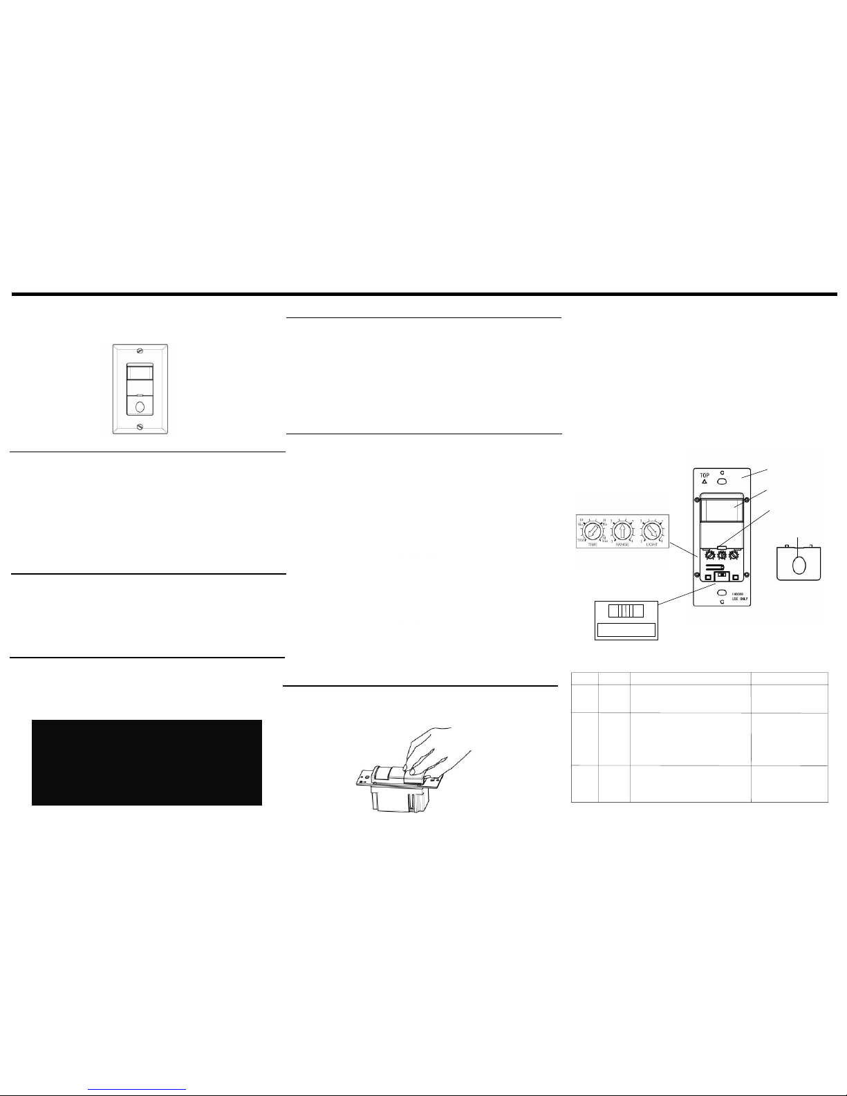
ADJUSTMENT
TDOS5
OCCUPANCY / VACANCY (2-IN-1)
SENSOR SWITCH
Incandescent ..............................................................................................................… 500W
Time Delay.............................................................................................…… 15Sec to 30Mins
Light Level..................................................................................................... 30 Lux--Daylight
Fluorescent......................................................................................................................500VA
Operation Temperature.......................................................................................... 32ºF--131ºF
Voltage ............................................................................................................... 120VAC,60Hz
Motor ......................................................................................................................…… 1/8Hp
COVERAGE
Figure 1
Max. 10'
on the sides
Max. 20'
from front
Installation
Height: 4' - 5'
Detection Range
Wiring Diagram
Hot
Black
Ground
Green
Load
Red
Neutral
White
The control panel cover is also the push button on the switch. Remove the push-button cover
plate by prying from the bottom of the push-button and pulling outward.
Control Panel Cover
LED Indicator
OFF OCC VAC
TIME
TEST
Min
10
20
Min
30
Min
RANGE
LIGHT
3
3
2
Mounting flange
Fresnel Lens
OFF OCC VAC
4
1
2
4
1
(Push Button)
Time dial
This dial adjusts the time delay. Default position: 15 Seconds (Test mode) Adjustable:
from 15 Seconds to 30 Minutes (clockwise)
Range dial
This dial adjusts the detection range. Default position: Center at 65%Adjustable: 30%
(Position 1) to 100% (Position 4).
Note: Use the greater setting for larger coverage area.
Light dial
The sensor may be adjusted to operate at the desired level of ambient light.
•
To do so, turn the dial counter clockwise for sensor to detect motion and operate
during low light or no light. Turn the dial clockwise for sensor to operate when
there’s more light in the area or even during daylight.
OCC
Mode
OFF
VAC
Description
Circuit is permanently opened.
(switched off)
Occupancy Mode:
Automatic On, Automatic Off
after set time delay.
Position
Left
Center
Right
Vacancy Mode: Manual On only,
Automatic Off after set time
delay.
Push-button Function
Manually toggles
None
Manually toggles
On / Off the load.
On/Off the load.
Off/ Occupancy/ Vacancy Mode Switch
Switch Type.............................................................................................................. Single Pole

4
5
6
WARRANTY INFORMATION
TROUBLESHOOTING
OPERATION
This device is warranted to be free of material and workmanship defects for 2 years from the
date of purchase. Original receipt or proof of purchase from an authorized retailer must be
presented upon warranty claim. ALL claims must be verified and approved by Top Greener,
Inc. Warranties from other Top Greener products may vary. This warranty is nontransferable
and does not cover normal wear and tear or any malfunction, failure, or defect resulting from
misuse, abuse, neglect, alteration, modification, or improper installation. To the fullest
extent permitted by the applicable state law, Top Greener shall not be liable to the purchaser
or end user customer of Top Greener products for direct, indirect, incidental, or
consequential damages even if Top Greener has been advised of the possibility of such
damages. Top Greener’ total liability under this or any other warranty, express or implied, is
limited to repair, replacement or refund. Repair, replacement or refund are the sole and
exclusive remedies for breach of warranty or any other legal theory.
© 2016 Top Greener Inc.
CA, U.S.A.
WWW.TOPGREENER.COM
0206160005
Off/ Occupancy/ Vacancy Mode Switch
The OFF position: Switch is turned off and will not detect motion. The push button will
not function.
OCCupancy position: The load will automatically turn on when motion is detected and
automatically turn off when the selected time delay has expired. The push button may be
used to manually turn ON/OFF the load and time delay will also take effect.
VACancy position: The load will turn on ONLY when the push button is used and
automatically turn off when the selected time delay has expired. The push button may be
used to manually turn ON/OFF the load and time delay will also take effect. If the time
delay has expired and the load turns off, the load will turn on again automatically if motion
is detected within 30 seconds.
The Load Flashes when switch is turned on:
Check the wire connection. Make sure the WHITE wire on the sensor
is connected to the NEUTRAL wire in the junction box. DO NOT
connect the WHITE wire on the sensor to any other wire besides
NEUTRAL.
DO NOT connect the WHITE (Neutral) wire and the RED (Load) wire
on the sensor together. Otherwise, the load will keep flashing.
The Load does not turn on when motion is detected:
1. Keep close to the sensor to make sure you are in the detection range.
2. Check the LED indicator on the sensor to see whether it flashes when motion is
detected. If LED indicator flashes when motion detected, please go to Step 3. If LED
indicator stays off when there is motion, please go to Step 4.
3. Make sure the sensor is in 'OCC' mode.
4. Check the wiring connection to make sure neutral wire has been connected and make
sure Hot and Load wires are not reversely connected.
The Load does not turn off:
1. Manually push the button to turn off the light. If the light keeps on, please go to step 4. If
the light is turned off, please go to step 2.
2. heck the time delay option. The time delay constantly restarts its countdown after the
last motion detected. Turn the Time Delay Knob to 15s (Test Mode) and make sure
there is no motion (Tape may be used to cover the fresnel lens while testing.)
3. Check for possible significant heat sources emitting within six feet (two meters) such as
high wattage light bulbs, portable heaters or HAVC vents which may be triggering the
sensor.
4. Check the wiring. Make sure no connection between Hot wire and Load.
The Load turns on when not desired:
1. Make sure there is no motion detected by the sensor.
2. Check for possible significant heat sources emitting within six feet (two meters) such as
high wattage light bulbs, portable heaters or HAVC vents which may be triggering the
sensor.
3. If the sensor is installed in a small room, turn the Range dial to a lower setting to avoid
false or unwanted detection from a open window or door.
4. Choose to use VAC mode instead of OCC mode to avoid false triggering.
 Loading...