

Page 1

Notes:
Upon receipt of the inverter and before any operation, please carefully read this instruction manual
thoroughly, also keep this manual for reference in the future. If you have any question or problem,
please no hesitate to contact your local SHANGCHIN representative. Thanks!
PREFACE
TOP GIN TG-300 is an optimized inverter specifically designed for variable torque applications.
This instruction manual describes installation, maintenance and inspection, troubleshooting, and
specifications of the TG-300 Read this instruction manual thoroughly before operation.
SHANGCHIN ELECTRONICS CORP.
General Precautions
●Some drawings in this manual are shown with the protective cover or shields removed, in order to
describe detail with more clarity. Make sure all covers and shields are replaced before operating this
product.
●This manual may be modified when necessary because of improvement of the product,
modification, or changes in specifications.
Such modifications are denoted by a revised manual
●To order a copy of this manual, if your copy has been damaged or lost, contact your SHANGCHIN
representative.
●SHANGCHIN is not responsible for any modification of the product made by the user, since that
will void your guarantee.
1
Page 2

CONTENTS
1 RECEIVING ··············································································································4
1.1 INSPECTION CHECKPOINTS ··························································································· 4
1.2 IDENTIFYING THE PARTS································································································5
2 INSTALLATION·······································································································6
2.1 LOCATION FOR THE INVERTER ·····················································································6
2.2 CLEARANCES ····················································································································7
3 WIRING······················································································································8
3.1 CONNECTION DIAGRAM································································································· 9
3.2 WIRING THE MAIN CIRCUIT ··························································································· 10
3.3 WIRING THE CONTROL CIRCUIT ··················································································· 13
3.4 WIRING INSPECTION········································································································ 14
4 OPERATION··············································································································15
4.1 OPERATION MODE SELECTION ····················································································· 16
4.2 TEST RUN CHECKPOINTS································································································ 17
4.3 SETTING THE LINE VOLTAGE USING JUMPER
(FOR 440V CLASS 18.5kW AND ABOVE) ··················································································· 17
4.4 TEST RUN···························································································································· 18
5 SIMPLE DATA SETTING ·······················································································23
5.1 DIGTAL OPERATOR KEY DESCRIPTION ······································································· 23
5.2 LED DESCRIPTION ············································································································ 24
6 PROGRAMMING FEATURES ··············································································26
6.1 CONSTANT SET-UP AND INITALIZATION ·····································································26
6.2 V/F PATTERN SETTING ····································································································· 26
6.3 OPERATION CONDITIONS ······························································································· 29
6.4 STOPPING METHOD·········································································································· 43
6.5 INTERFACE CIRCUITS WITH EXTERNAL DEVICES···················································· 46
6.6 ADJUSTING MOTOR TORQUE························································································· 56
6.7 MOTOR PROTECTION······································································································· 57
6.8 PID CONTROL ····················································································································59
6.9 ENERGY SAVING CONTROL···························································································· 61
6.10 MODBUS CONTROL·········································································································· 63
2
Page 3

7 MAINTENANCE AND INSPECTION ··································································64
7.1 PERIODIC INSPECTION ···································································································· 65
7.2 PARTS REPLACEMENT SCHEDULE (GUIDELINES)····················································· 65
8TROBULESHOOTING·····························································································66
8.1 FAULT DIAGNOSIS AND CORRECTIVE ACTIONS ·······················································66
8.2 ALARM DISPLAY AND EXPLANATION ·········································································69
8.3 MOTOR FAULTS AND CORRECTIVE ACTIONS ···························································· 70
APPENDIX 1 SPECIFICATIONS ·············································································71
APPENDIX 2 DIMENSIONS (mm)···········································································72
APPENDIX 3 TYPICAL CONNECTION DIAGRAM···········································73
3.1 BRAKING RESISTOR UNIT······························································································· 73
3.2 BRAKING UNIT AND BRAKING RESISTOR UNIT ························································ 74
APPENDIX 4 CONSTANT LIST···············································································75
APPENDIX 5 DIGT AL OPERATOR MONITOR DISPLAY ································81
BRAKING UNIT APPLICATION LIST···································································83
SEPARATELY -INSTALLED TYPE BRAKING RESISTOR································84
3
Page 4
1. RECEIVING
SOURC
CAUTION
●Do not install or operate any inverter which is damaged or has missing parts.
Failure to observe this caution may result in personal injury or equipment damage
This chapter describes how to inspect the inverter after delivery to the user.
1.1 INSPECTION CHECKPOINTS
(1)Receiving Checkpoints
Checkpoints Description
Does the inverter model number correspon
the purchase order?
Are any parts damaged?
Check the model number on the nameplate on the
side of the TG-300
Visually check the exterior and verify that there
was no damage during transport.
Is hardware properly seated and securely
tightened?
Was an instruction manual received?
Remover inverter front cover.
Check all visible hardware with appropriate tools.
TG-300 instruction manual
If any of the above checkpoints are not satisfactory, contact your SHANGCHIN representative.
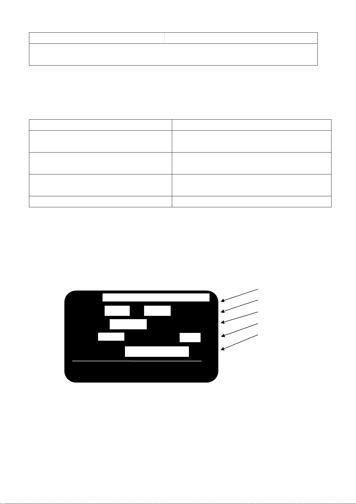
(2)Checking the Nameplate Data
(a)Nameplate Date
Example of TG-300
Model
TG 300 -
E V H z
CAPACITY kVA
Input power supply
Output capacity
Output power supply
Manuf. No.
VOLTS V CURRENTS A
SERIAL NO.
TOP GIN MADE IN TAIWAN
4
Page 5
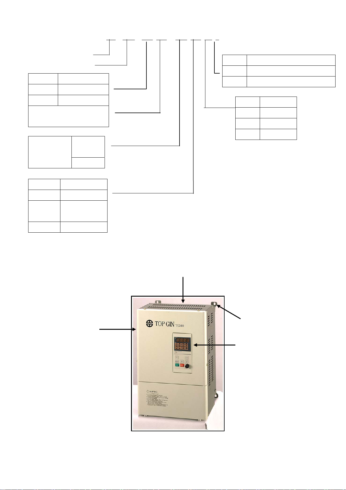
●Model Designation
TG – 300 – L 100 – A 2 T 1
TOP GIN
IGBT Series
Symbol Voltage
L
H
Max applicable motor
output (10Hp)
3φ220V Series
3φ440V Series
Symbol Enclosure
Braking
resitstor
A:
Without
B:With
Operator
1 Black
2 Digital with
VR
0 Open shdssis type (IP00)
1 Enclosed wall-mounted type(IP20)
Symbol Specification
T Standard
E CE mark
U UL
3 LCD with VR
1.2 IDENTIFYING THE PARTS
Front Cover
Protective Cover (top/bottom)
4 Mounting Holes
Digital Operator
Ventilation Slots
Flg. 4 Configuration of TG-300
5
Page 6

2 . INSTALLATION
CAUTION
●Lift the cabinet by the base. When moving the unit, never lift by the front cover.
Otherwise, the main unit may be dropped causing damage to the unit.
●Mount the inverter on nonflammable material (i.e. metal).
Failure to observe this caution can result in a fire.
●When mounting units in an enclosure, install a fan or other cooling device to keep the intake air
temperature below 45℃.
Overheating may cause a fire or damage to the unit.
This chapter describes configuration, location and clearances when mounting the TG-300.
2.1 LOCATION FOR THE INVERTER
To ensure proper performance and long operating life, follow the recommendations below when
choosing a location for installing the TG-300. Make sure the inverter is protected from the following
conditions:
□ Extreme cold and heat.
□ Use only within ambient temperature range:-10℃ to +40℃
□ Rain, moisture. (For enclosed wall-mounted type)
□ Oil sprays, splashes
□ Salt spray
□ Direct sunlight. (Avoid using outdoors.)
□ Corrosive gases or liquids.
□ Dust or metallic particles in the air.(For enclosed wall-mounted type)
□ Physical shock, vibration.
□ Magnetic noise. (Example: welding machines, power devices, etc.)
□ High humidity.
□ Radioactive materials.
□ Combustibles:thinners, solvents, etc.
6
Page 7
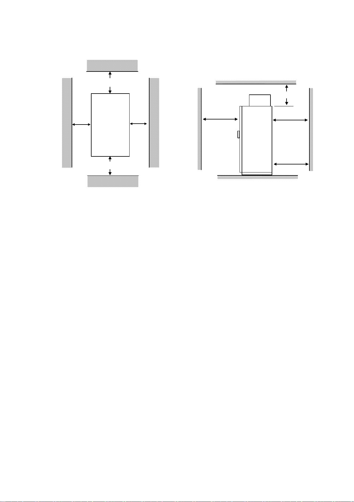
2.2 CLEARANCES
Install the TG-300 vertically and allow sufficient clearances for effective cooling as shown below.
Note:
150mm
Inverter
Front
face
100mm
150
500
Door width
50mm50mm
150
+ 100
500
For
front/rear
door
Door width
+ 100
1.The clearances required at top/bottom and both sides are common in open chassis type (IP00) and
enclosed wall-mounted type (IP20).
2.Remove the top and bottom covers to use the open chassis type of 220V/440V 15Kw or less.
3.For the external dimensions and mounting dimensions, refer to Appendix 2 “DIMENSIONS”.
4.Allowable intake air temperature to the inverter:
●Open chassis type :-10℃ to +45℃
●Enclosed wall-mounted type:-10℃ to +40℃
5. Ensure sufficient space for the sections at the upper and lower parts marked with * in order to permit
the flow of intake/exhaust air to/from the inverter.
7
Page 8

3. WIRING
WA R IN G
●Only commence wiring after verifying that the power supply is turned OFF.
Failure to observe this warning can result in an electrical shock or a fire.
●Wiring should be performed only by qualified personnel.
Failure to observe this warning can result in an electrical shock or a fire.
●When wiring the emergency stop circuit, check the wiring thoroughly before operation.
Failure to observe this warning can result in personal injury.
CAUTION
●Verify that the inverter rated voltage coincides with the AC power supply voltage.
Failure to observe this warning can result in personal injure or a fire.
●Do not perform a withstand voltage test of the inverter.
It may cause semi-conductor elements to be damaged.
●To connect a braking resistor, braking resistor unit or braking unit, follow the procedures described
in APPENDIX 3.
Improper connection may cause a fire.
●Tighten terminal screws to the specified tightening torque.
Failure to observe this caution can result in a fire.
This chapter describes the main circuit wiring and the control circuit wiring of the TG-300.
8
Page 9
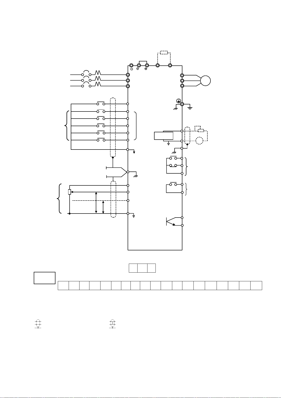
3.1 CONNECTION DIAGRAM
Below is connection diagram of the main circuit and control circuit. Using the digital operator, the
motor can be operated by wiring the main circuit only.
Breaking Resistor (Option)
3-Phase
Power Supply
200 to 240V
345 to 480V
50/60 HZ
Factory
Setting
Master
Frequency
Reference
MCCB
R
S
TL3(T)
Forward Run/Stop
Reverse Run/Stop
External Fault
Fault Reset
Multi-step Speed Setting 1
Multi-step Speed Setting 2
2kΩ
0 to +10V
4 to 20mA
0V
P
P
1
2
B1 B2
L1(R)
L2(S)
S1 Forward Run
when CLOSED
S2
S3
Multi-function
S4
Contact input
S5
S6
Sequence Commom
SC
Terminal (0V)
G
Shield Sheath
Connection
Terminal
Freq. Setting Power
FS
Supply +15V 20mA
FV
Master Freq. Ref.
0 to 10V (20kΩ)
FI
Master Freq. Ref.
4 to 20mA (250Ω)
[0 to 10V(20kΩ)input available]
FC
0V
Analog
Monitor
U(T1)
V(T2)
W(T3)
AM
AC
MA
MB
MC
M2
M3
TG 250
Motor
IM
Ground (100Ω or less)
Multi-function Analog Output 0
to +10V
+
-
(G)
Multi-function Contact Output
Contact Capacity:250 VAC 1A or less
30 VDC 1A or less
(Fault Output Signal at Factory Setting)
M1
Multi-function Contact Output
250 VAC 1A or less
30 VDC 1A or less
(Signal during Running at Factory Setting)
M4
OPEN COLLECTOR OUTPUT
(ZERO SPEED SIGNAL)
(OPTION)
(Output Frequency at Factory
FM
Setting)
TG 300
Connection Diagram
W2
ON OFF
G
S1 S2 S3 SC SC S4 S5 S6 FV FI FS FC AM AC M1 M2 MA MB MC
VR SET HZ W2 OFF
REMOTE SET HZ W2 ON
Note:
P
indicates shielded wires and
1.
indicates twisted-pair shielded wires.
2.Voltage or current input for the master frequency reference can be selected by constant H042.
Voltage reference input is preset at the factory.
3.Control circuit terminal FR of +15 V has a maximum output current capacity of 20 mA.
4.Multi-function analog output should be used for monitoring meters (e.g. output frequency meter)
and should not be used for feedback control system.
9
Page 10

3.2 WIRING THE MAIN CIRCUIT
WA R NI N G
●Make sure to ground the ground terminal
(Ground resistance 220V class:100Ω or less. 440V class:10Ω or less)
Failure to observe this warning can result in an electrical shock or a fire.
CAUTION
●Never connect the AC main circuit power supply to output terminals U,V and W.
The inverter will be damaged and invalidate the guarantee.
(1)Wiring Precautions for Main Circuit Input
(a)Installation of Molded-case Circuit Breaker (MCCB)
Make sure to connect MCCBs of fuses between AC main circuit power supply and TG-300 input
terminals L1, L2 and L3 to protect wiring.
(b)Installation of Ground Fault Interrupter
When connecting a ground fault interrupter to input terminals L1, L2 and L3, select one that is not
affected by high frequency.
(c)Installation of Magnetic Contactor
Inverters can be used without a magnetic contactor (MC) installed at the power supply side. When
the main circuit power supply is shut OFF in the sequence, a magnetic contactor (MC) can be used
instead of a molded-case circuit breaker (MCCB). However, when a magnetic contactor is switched
OFF at the primary side, regenerative braking does not function and the motor coasts to a stop.
● The load can be operated/stopped by opening/closing the magnetic contactor at the primary side.
However, frequent switching may cause the inverter to malfunction.
● When using a braking resistor unit, use a sequencer to break power supply side on overload relay
trip contact. If the inverter malfunctions, the braking resistor unit may be burned out.
(d)Terminal Block Connection Sequence
Input power supply phases can be connected to any terminal regardless of the order of L1, L2 and L3
on the terminal block.
(e)Installation of AC Reactor
When connecting an inverter (220V/440V 15Kw or less) to a large capacity power supply
transformer (600Kva or more), or when switching a phase advancing capacitor, excessive peak
current flows in the input power supply circuit, which may damage the converter section. In such
cases, install a DC reactor (optional) between inverter 1 and 2 terminals or an AC reactor
(optional) on the input side. Installation or a reactor is effective for improvement of power factor on
the power supply side.
10
Page 11

(f)Installation of Surge Suppressor
For inductive loads (magnetic contactors, magnetic relays, magnetic valves, solenoids, magnetic
brakes, etc.) connected near the inverter, use a surge suppressor simultaneously.
(g)Prohibition of Installation of Phase Advancing Capacitor
If a phase advancing capacitor or surge suppressor is connected in order to improve the power factor,
it may become overheated and damaged by inverter high harmonic components. Also, the inverter
may malfunction because of overcurrent.
(2)Wiring Precautions for Main Circuit Output
(a)Connection of Terminal Block and Load
Connect output terminals U, V and W to motor lead wires U, V and W. Verify that the motor rotates
in the forward direction (CCW:counterclockwise when viewed from the motor load side) with the
forward run command. If the motor rotation is incorrect, exchange any two of output terminals U,V
or W.
(b)Strict Prohibition of Connection of Input Power Supply to Output Terminals
Never connect input power supply to output terminals U, V and W.
(c)Strict Prohibition of Short Circuiting or Grounding of Output Circuit
Never touch the output circuit directly or put the output line in contact with the inverter case.
Otherwise, it may cause an electrical shock or grounding. In addition, never short circuit the output
line.
(d)Prohibition of Connection of Phase Advancing Capacitor or LC/RC Noise Fitter
Never connect a phase advancing capacitor or LC/RC noise, filter to the output circuit.
(e) Avoidance of Installation of Magnetic Starter
Do not connect a magnetic starter or magnetic contactor to the output, circuit.
If the load is connected while the inverter is running, the inverter overcurrent
protective circuit operates because of inrush current.
(f) Installation of Thermal Overload Relay
An electronic overload protective function is incorporated into the inverter.
However, connect a thermal overload relay when driving several motors with one inverter or when
using a multi-pole motor. When using a thermal overload relay, set inverter constant H033 to 0.
Additionally, for thermal overload relay, at 50Hz set the same rated current value as that described
on the motor nameplate, or at 60Hz 1.1 times larger than the rated current value described on the
motor nameplate.
11
Page 12

(g) Wiring Distance between Inverter and Motor
If the total wiring distance between inverter and motor is excessively long and the inverter carrier
frequency (main transistor switching frequency) is high, harmonic leakage current from the cable
will adversely affect the inverter and peripheral devices.
If the wiring distance between inverter and motor is long, reduce the inverter carrier frequency as
described below. Carrier frequency can be set. by constant H050.
Wiring Distance between Inverter and Motor
Wiring Distance between
Up to 50m Up to 100m More than 100m
Inverter and Motor
Carrier Frequency
(Set value of constant H050)
15kHZ or less
(6)
10kHZ or less
(4)
5kHZ or less
(2)
(3)Grounding
●Ground resistance
220 V class:100Ω or less, 440 V class:10Ω or less
●Never ground TG-300 in common with welding machines, motors, or other large-current electrical
equipment. Run all the ground wires in a conduit separate from wires for large-current electrical
equipment.
●Use the ground wires described in tables below and keep the length as short as possible.
●When using several TG-300 units side by side, ground the units as shown below
(b)Acceptable(a)Acceptable
(c)Not Acceptable
Grounding of Three TG-300 Units
12
Page 13

3.3 WIRING THE CONTROL CIRCUIT
The following table outlines the functions of the control circuit terminals
Wire according to each terminal function.
(1) Functions of Control Circuit Terminate
Control Circuit Terminals
Classification Terminal Signal Function Description Signal Level
S1 Forward run/stop
S2 Reverse run/stop
S3 External fault input
S4 Fault reset input
Sequence Input Signal
Analog Input Signal
Sequence Output Signal
S5
S6
SC
FS
FV
FI
FC
G
M1
M2
MA
MB
MC
AM Frequency meter output
AC Common
Analog
Output
Signal
Multi-step speed
reference 1
Multi-step speed
reference 2
Sequence control input
common terminal
+15V Power supply
output
Frequency reference
input (voltage)
Frequency reference
input (current)
Common terminal for
control circuit
Connection to shield
searth of signal lead
During running
(NO contact)
Fault contact output
(NO/NC contact)
Forward run when closed, stop
when open
Reverse run
when closed,
stop when open
Fault when
closed, normal
state when
open
Reset when
closed
Effective when
closed
Effective when
closed
For analog command +15V power
supply
0 to
+10V/100%
4 to
20mA/100%
Closed when
running
Fault when
closed between
terminals MA
and MC
Fault when
open between
terminals MB
and MC
0 to +
10V/100%
Freq.
Multi-function
contact inputs
(H035 to H039)
---
H042 = 0:FV
effective
H042 = 0:FI
effective
0V ---
--- ---
Multi-function
contact output
(H041)
Multi-function
contact output
(H040)
Multi-function
contact analog
monitor 1
(H048)
Photo-coupler
insolation
Input :+24VD
8mA
+15V
(Allowable
current 20mA
max.)
0 to +10V
(20 kΩ)
4 to 20mA
(250Ω)
Dry contact
Contact
capacity:
250VAC 1 A or
less
30VDC 1 A or
less
Dry contact
Contact
capacity:
250VAC 1 A or
less
30VDC 1 A or
less
0 to +10V 2mA
or less
13
Page 14

(2) Wiring the Control Circuit Terminals
ON
Screwdriver Blade Width
Insert the wire into the lower part of the terminal block and connect it tightly with a screwdriver.
Wire sheath strip length must be 7 mm.
7mm
(3) Precautions on Control Circuit Wiring
●Separate control circuit wires from main circuit wires and other power cables to prevent erroneous
operation caused by noise interference.
●Use twisted shielded or twisicd-pair shielded wire for the control circuit line and connect the
shielded sheath to the inverter terminal G.
Wiring distance should be less than 50 m.
3.4 WIRING INSPECTION
After completing of installation and wiring, check for the following items. Never use
control circuit buzzer check-
□ Wiring is proper.
□ Wire clippings or screws are not left in the unit.
□ Screws are securely tightened.
□ Bare wire in the terminal does not contact other terminals
14
Page 15

4 OPERATION
WA R NI N G
●Only turn ON the input power supply after replacing the front cover. Do not remove the cover
while current is flowing.
Failure to observe this warning can result in an electrical shock.
●When the retry function (H057) is selected, do not approach the inverter or the load, since it may
restart suddenly after being stopped.
(Construct machine system, so as to assure safety for personnel, even if the inverter should restart.)
Failure to observe this warning can result in personal injury.
●Since the stop button can be disabled by a function setting, install a separate emergency stop
switch.
Failure to observe this warning can result in personal injury.
CAUTION
●Never touch the heatsink or discharging resistor since the temperature is very high.
Failure to observe this caution can result in harmful burns to the body.
●Since it is easy to change operation speed from low to high speed, verify the safe working range of
the motor and machine before operation.
Failure to observe this caution can result in personal injury and machine damage
●Install a holding brake separately if necessary.
Failure to observe this caution can result in personal injury
●Do not change signals during operation.
The machine or the inverter may be damaged
●Ail the constants of the inverter have been preset at the factory. Do not change the settings
unnecessarily.
The inverter may be damaged. For supply voltage, follow Par. 4.3.
This chapter describes the basic operation procedures of the TG-300.
15
Page 16

4 .1 OPERATION MODE SELECTION
The TG-300 has two operation modes, LOCAL and REMOTE, as described below. These two
modes can be selected by the digital operator "LOCAL/REMOTE" key only while the operation is
stopped. The selected operation mode can be verified by observing the digital operator SEQ and
REF LEDs as shown below. The operation mode is set to REMOTE (run by control circuit terminals
FV and FI frequency reference and run command from a control circuit terminal) prior to shipment.
Multi-function contact inputs from control circuit terminals S3 to S6 are enabled in both operation
modes LOCAL/REMOTE.
●LOCAL :Both frequency reference and run command are set by the digital operator. SEQ
and REF LEDs go OFF.
●REMOTE:Master frequency reference and run command can be selected as described below.
Reference Selection in REMOTE Mode (H002: Operation Method Selection)
Setting Operation Method Selection
0
1
2
3
4
Operation by run command from digital
operator
Operation by run command from control
circuit terminal ON
Operation by run command from digital
operator
Operation by run command from control
circuit terminal
Operation by run command from digital
operator
SEQ
LED
OFF
OFF
ON
OFF
Reference Selection
Master frequency reference
from digital operator
Master frequency reference
from
digital operator
Master frequency reference
from
control circuit terminals FV
and FI
Master frequency reference
from
control circuit terminals FV
and FI
Master frequency reference set
by serial communication
REF
LED
OFF
OFF
ON
ON
ON
5
6
7
8
Operation by run command from control
ON
circuit terminal
Operation by run command from serial
ON
communication
Operation by run command from serial
communication ON
Operation by run command from serial
communication
ON
Master frequency reference set
by serial communication
Master frequency reference set
by serial communication
Master frequency reference
from
digital operator
Master frequency reference
from
control circuit terminals FV
and FI
ON
ON
OFF
ON
16
Page 17
4.2 TEST RUN CHECKPOINTS
To assure safety, prior to initial operation, disconnect the machine coupling so that the motor is
isolated from the machine. If initial operation must be performed while the motor is still coupled to
the machine, use great care to avoid potentially hazardous conditions. Check the following items
before a test run.
□ Wiring and terminal connections are correct.
□ No short circuit caused by wire clippings.
□ Screw-type terminals are securely tightened.
□ Motor is securely mounted.
□ All items are correctly earthed(grounded).
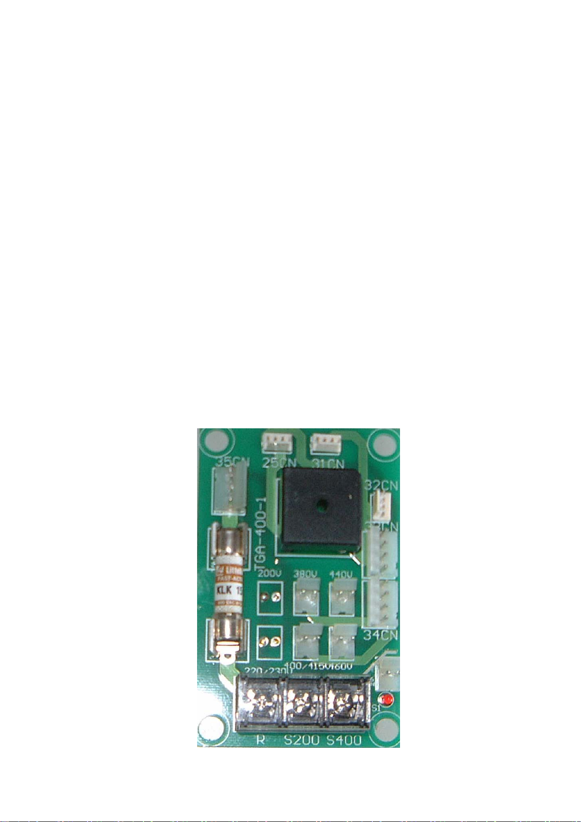
4.3 SETTING THE LINE VOLTAGE USING JUMPER
(FOR 440V CLASS 55kW AND ABOVE)
Set the line voltage jumper according to the main circuit power supply.
Insert the jumper at the appropriate location corresponding to the input line voltage
It has been preset at the factory to 440V.
Line Voltage Jumper (For 440V Class 55W to 300kW)
17
Page 18
4.4 TEST RUN
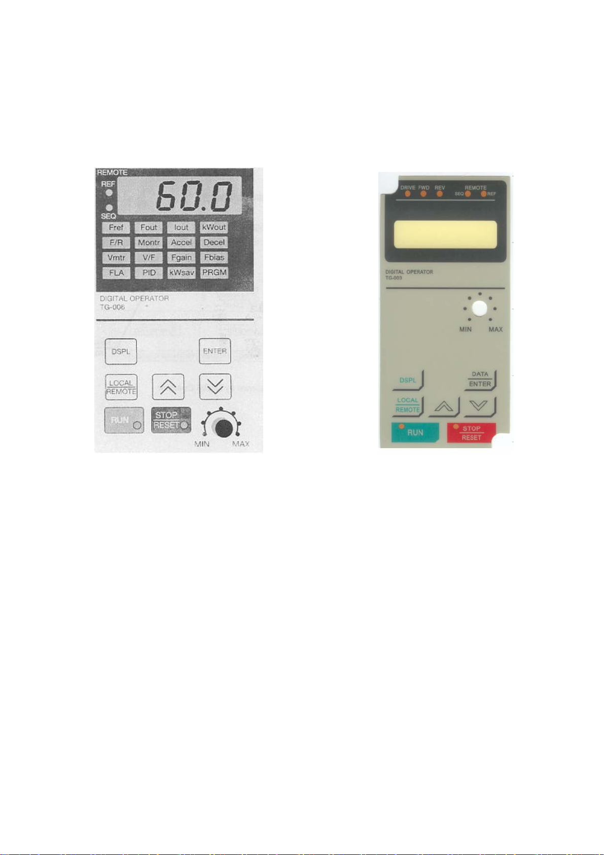
(1) Digital Operator Display at Power-up
When the system is ready for operation, turn ON the power supply. Verify that the inverter powers
up properly. If any problems are found, turn OFF the power supply immediately. The digital operator
display illuminates as shown below
Digital Operator Display Digital Operator Display
LED LCD
18
Page 19
(2) Operation Check Points
Check the following items during operation
□ Motor rotates smoothly.
□ Motor rotates in the correct direction.
□ Motor does not have abnormal vibration or noise.
□ Acceleration and deceleration are smooth.
□ Current matches the load flow.
□ Status indicator LEDs and digital operator display are correct
(3) Example of Basic Operation
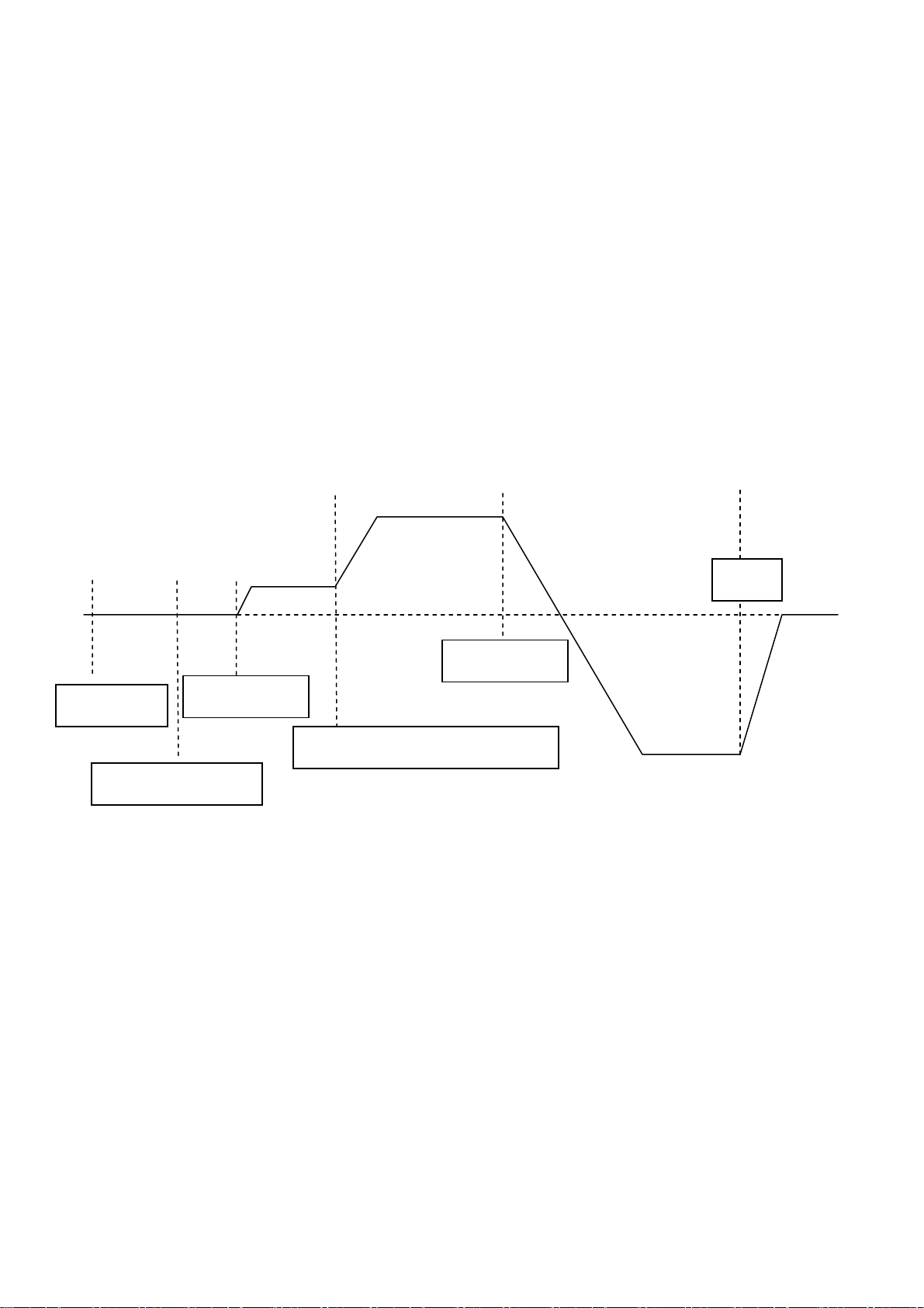
(a) Operation by Digital Operator
The diagram below shows a typical operation pattern using the digital operator
f Forward g h
60 Hz
c d e Forward
25Hz
Power ON
Reverse
Forward Run
Frequency Reference Change
60 Hz
Frequency Setting
Operation Sequence by Digital Operator
Reverse Run
Stop
19
Page 20
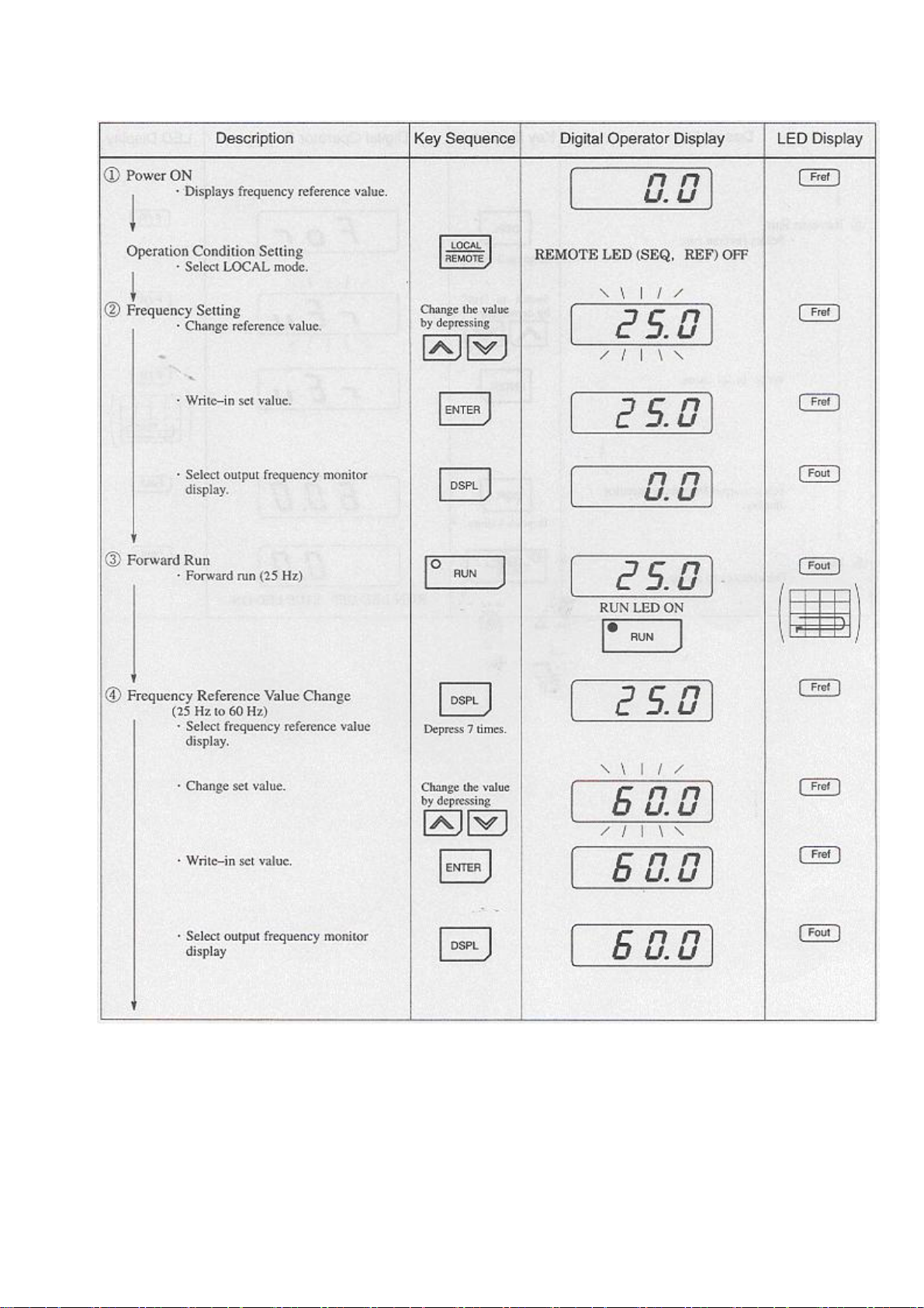
Typical Operation by Digital Operator
20
Page 21
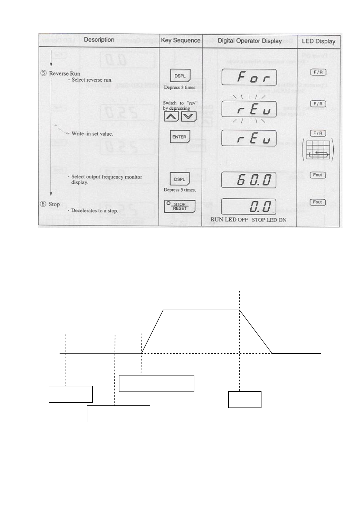
Typical Operation by Digital Operator (Cont’d)
(b)Operation by Control Circuit Terminal Signal
The diagram below shows a typical operation pattern using the control circuit terminal signals.
f
Forward
60 Hz
c d e
Power ON
Reference Operation
Stop
Frequency Setting
Operation Sequence by Control Circuit Terminal Signal
21
Page 22
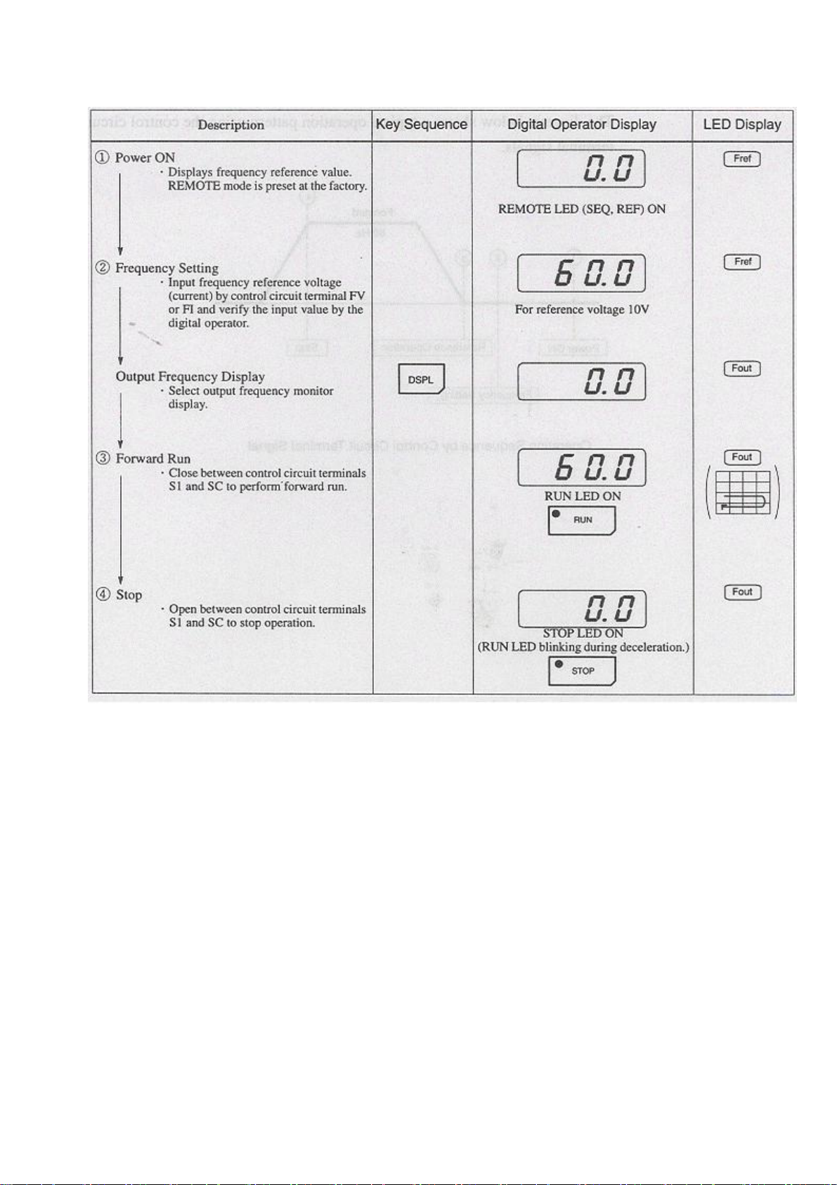
Typical Operation by Control Circuit Terminal Signal
22
Page 23
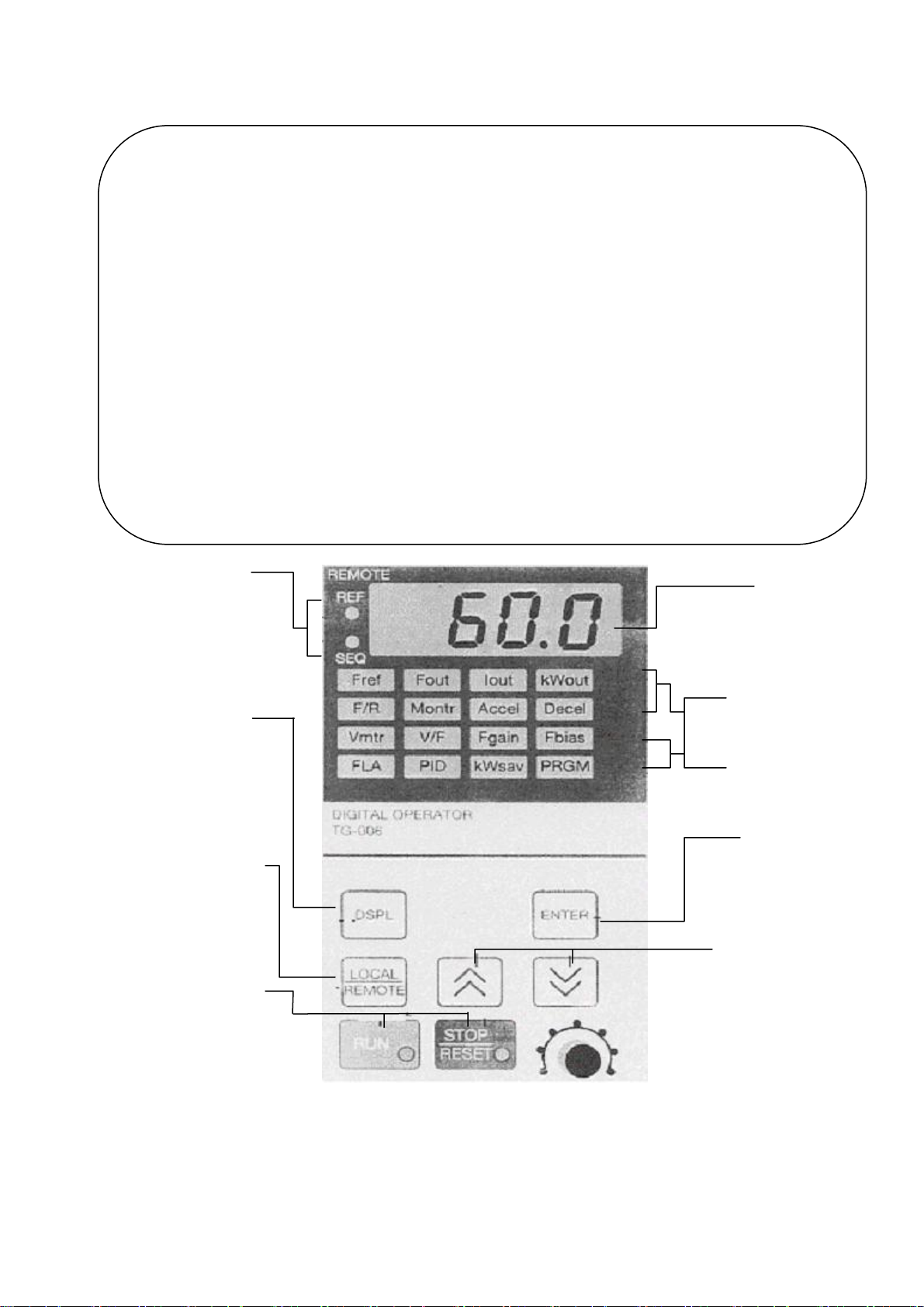
5 SIMPLE DATA SETTING
5.1 DIGITAL OPERAT KEY DESCRIPTION
Fref Fout Iout kwout
Frequency Output frequency Output current Output power
Reference monitor monitor monitor
Setting/monitoring
F/R Montr Accel Decel
FWD/REV run Monitor Acceleration Deceleration time
Command Selection Time
Selection
Vmtr V/F Fgain Fbias
Motor rated V/f pattern Frequency Frequency
Voltage selection Reference gain reference bias
FLA P/D Kwsalv PRGM
Motor rated current PID selection Energy saving
selection
Constant No/data
LED lights when inverter is controlled by
control circuit terminal commands.
SEQ:When RUN/STOP signal is through
terminals.
REF:When frequency reference is through
terminals.
Display Selection Key
Depressing this key changes the
display. See next page for
explanation
Operation Mode Selection Key
Mode Display LEDs
Depressing this key changes the mode
(LOCAL or REMOTE)
Operation Command Keys
Operation command keys operate the inverter.
Display
Displays the set value of each function and
monitor values such as output frequency and
output current (4 digits)
The selected function lights and allows changing
operation
Constants can be set only during a stop
Depressing this key recalls and
displays indicated data from
memory.
Depressing a second time enters the
displayed data into memory
Changes numbers such as set values
and constants
Λ:Increase Ⅴ:Decrease
Quick-Start LEDs
During Operation
Monitors/constants can be set during
During a Stop
Enter Key
Number Change keys
STOP/RESET Key:Stop command LED
Lights when STOP key is depressed. (It changes to
a reset key when a fault occurs.)
MIN MAX -----VR Set
RUN Key:Run command LED lights when the
RUN key is depressed.
23
Page 24

5 .2 LED DESCRIPTION
By using the quick-start LEDs on the digital operator, simple operation of the inverter is possible.
Each quick-start LED is selected each time [DSPL] key is depressed. Following is a flowchart
describing quick-start LED selection. (Example of model TG-300-L50B2T)
24
Page 25
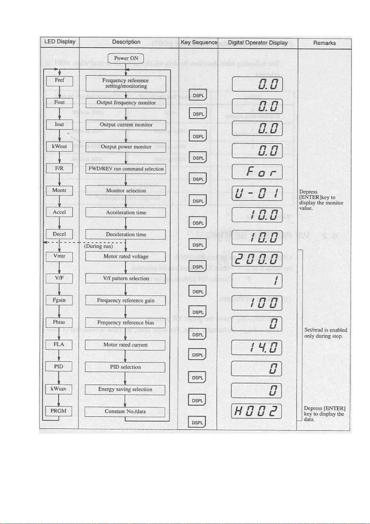
LED Description
25
Page 26

6 PROGRAMMING FEATURES
6.1 CONSTANT SET-UP AND INITIALIZATION
(1) Constant Selection/Initialization (H001)
The following table describes the data which can be set or read when H001 is selected.
Setting Constant that can be set Constant that can be read
0
(Constant write disable)
1
(Factory setting)
2 H001 to H049 H001 to H108
3 H001 to H108 H001 to H108
4.5 Not used (disabled)
6
7
*Refer to page 60
6.2 V/F PATTERN SETTING
V/f pattern can be set by constant H010.
H001 H001 to H108
H001 to H034 H001 to H108
Initialize:2-wire sequence
Initialize:3-wire sequence*
Set value 0 to E:Preset V/f pattern can be selected
F:Custom V/f pattern can be set.
(1) Preset V/f Pattern
The following shows the preset V/f patterns.
(The voltages are for 220V class. For 440V class, the value is twice that of 220V class.)
26
Page 27

Preset V/f Pattern (H010=0 to E)
*1 Consider the following items as the conditions for selecting a V/f pattern. They must be suitable
for:
●The voltage and frequency characteristics of motor
●The maximum rotation speed of motor
*2 Select high starting torque only in the following conditions. Normally, this selection is not
required.
●The wiring distance is long (150 m and above).
●Voltage drop al startup is large.
●AC reactor is inserted in the input or output of the inverter.
●A motor smaller than the nominal output of the inverter is used.
27
Page 28

(2)Custom V/f Pattern
Set each pattern when using a special motor (high-speed motor, etc.) or when requiring special
torque adjustment of machine.
Make sure to satisfy the following conditions for the setting of constants H012 to H018.
H017≦H015<H014≦H012
V (Voltage)
H013
H016
H018
f
0 H017 H015 H014 H012 (Frequency)
Constant
No.
Name Unit Setting Range Factory
Setting
H012 Max. output frequency 0.1Hz 50.0-400.0 Hz 60.0Hz
H013 Max. voltage 0.1V 0.1-255.0V* 220.0V*
H014 Max. voltage output frequency
0.1Hz 50.0-400.0 Hz 60.0Hz
(base frequency)
H015 Mid. output frequency 0.1Hz 0.1-399.9 Hz 3.0Hz
H016 Mid. output frequency voltage 0.1V 0.1-255.0V* 15.0V*
H017 Min. output frequency 0.1Hz 0.1-10.0 Hz 1.5Hz
H018 Min. output frequency voltage 0.1V 0.1-50.0V* 10.0V*
*For 440V class, the value is twice that of 220V class.
Increasing the voltage of the V/f pattern increases motor torque, but an excessive increase may cause
the following:
●Inverter malfunction because of motor overexcitation
●Motor overheat or excessive vibration
Increase voltage gradually while verifying the motor current.
28
Page 29

6.3 OPERATION CONDITIONS
(1)Reverse Run Prohibit (H006)
“Reverse run disabled” setting does not accept a reverse run command from the control circuit
terminal or digital operator. This setting is used for applications where a reverse run command can
cause problems.
Setting Description
0 Reverse run enabled
1 Reverse run disabled
(2)Multi-Step Speed Selection
By combining frequency reference and input terminal function selections, up to 4 steps of speed can
be set.
4-step speed change
H002 =1 (operation mode selection)
H025 =30.0 Hz
H026 =40.0 Hz
H027 =50.0 Hz
H028 =60.0 Hz
H038 =9 (Multi-function contact input terminal S5)
H039 =10 (Multi-function contact input terminal S5)
FWD Run/Stop
REV Run/Stop
External Fault
Fault Reset
Multi-step Speed Ref.1
Multi-step Speed Ref.2
S1
S2
S3
S4
S5
S6
Multi-function
Contact input
SC
29
Page 30

Frequency
Reference
30.0Hz
(H026)
40.0Hz (H025)
(H027)
50.0Hz
(H028)
60.0Hz
FWD (REV) Run/Stop ON
Multi-step Speed Ref.1 ON ON
(Terminal S5)
Multi-step Speed Ref.2 ON
(Terminal S6)
(3)Operating at Low Speed
Set jog frequency reference selection in multi-function contact input terminals (S2 to S6). Then input
a forward (reverse) run command. Operation is enabled at the jog frequency set in H 029. When
multi-step speed references 1 or 2 are input simultaneously with the jog frequency reference, the jog
frequency reference has priority.
Name Constant No. Setting
Jog frequency reference H029
Multi-function contact input
(Factory setting:6.0Hz)
Set to “11” (jog Frequency
(H035,H036,H037,H038,H039)
selection (S2 to S6)
selection) for any constant.
30
Page 31

(4)Adjusting Frequency Setting Signal
When the frequency reference is output by an analog input of control circuit terminals FV and FI, the
relationship between the analog input (voltage/current) and the frequency reference can be set.
Frequency Reference
Max. Output Frequency
¯
Gain
100
Max. Output Frequency
¯
Bias
100
0 V 10 V
(4 mA) (20 mA) ( ) indicates when current
reference input is selected.
(a)Frequency Reference Gain (H046)
The frequency reference at the analog input value of 10V (20mA) can be set in units of 1%. (H012
Max. output frequency:100%)
Factory setting:100%
(b) Frequency Reference Bias (H047)
The frequency reference at the analog input value of 0V (4mA) can be set in units of 1%. (H012
Max. output frequency:100%)
Factory setting:0%
Typical setting
․To operate the inverter with frequency reference of 0% to 100% at 0 to 5V input
Max. Output
Frequency (100%)
0%
0 V 5 V 10 V
Gain:Constant H046=200
Bias:ConstanTH047=0
31
Page 32

․To operate the inverter with frequency reference of 50% to 100% at 0 to 10V input
Max. Output
Frequency (100%)
50%
0 V 10 V
Gain
:Constant H046= 100
Bias
:Constant H047 = 50
(5) Adjusting Frequency Upper and Lower Limits
Internal
Frequency
Reference Frequency Reference
Upper Limit (H030)
Frequency Reference Lower Limit (H031)
Set Frequency Reference
(a) Frequency Reference Upper Limit (H030)
Sets the upper limit of the frequency reference in units of 1%
(H012 Max. output frequency: 100%)
Factory setting: 100%
(b) Frequency Reference Lower Limit (H031)
Sets the lower limit of the frequency reference in units of 1%.
(H012 Max. output frequency: 100%)
When operating at a frequency reference of 0, operation is continued at the frequency reference,
lower limit. However, when the frequency lower limit is set to less than the min. output frequency
(H017), operation is not performed.
Factory setting: 0%
32
Page 33

(6) Using T wo Accel/Decel Times
Decel Time 1
Output Frequency (H020)
Accel Time 2 Decel Time 2*
Accel Time 1 (H021) (H022)
(H019) Decel Time 1*
(H020)
Time
FWD(REV) Run Command ON OFF ON
Accel/Decel Time
Selection (Terminals S2 to S6) ON
*When “deceleration to stop” is selected (H400=0)
By setting multi-function contact input selection (H035. H036, H037, H038 orH039) to "12
(accel/decel time selection)", accel/decel time is selected by turning ON/OFF the accel/decel time
selection (terminal S2, S3, S4, S5 or S6).
At OFF
At ON
:H019 (accel time 1), H020 (decel time 1)
:H021 (accel time 2), H022 (decel time 2)
Constant
No.
H019 Accel time 1 0.1s (1 s for 100 s and
Name Unit Setting
Factory Setting
Range
0.0 to 3600s 10.0s
above)
H020 Decel time 1 0.1s (1 s for 100 s and
0.0 to 3600s 10.0s
above)
H021 Accel time 2 0.1s (1 s for 100 s and
0.0 to 3600s 10.0s
above)
H022 Decel time 2 0.1s (1 s for 100 s and
above)
●Accel time
Set the time needed for output frequency to reach 100% from 0%
●Decel time
Set the time needed for output frequency to reach 0% from 100%
33
0.0 to 3600s 10.0s
Page 34

(7)Automatic Restart after Momentary Power Loss (H051)
When momentary power loss occurs, operation restarts automatically.
Setting Description
0 Not provided (Factory setting)
1* Continuous operation after power recovery within 2 sec
2* Continuous operation after power recovery within control logic time (No fault output)
*Hold the operation command to continue operation after recovery from a momentary power loss.
*When 2 is selected, operation restarts if power supply voltage reaches its normal level. No fault
signal is output.
(8)Soft-start Characteristics (H023)
TO prevent shock during machine starting/stopping, accel/decel can be performed in S-curve pattern.
Setting S-curve Characteristic Time
0 S-curve not provided
1 0.2 sec (Factory setting)
2 0.5 sec
3 1.0 sec
None:S-curve characteristics time is the time from accel/decel rate 0 to a regular accel/decel rate
determined by the set accel/decel time.
Frequency Reference
Output Frequency
Output Frequency
Time
S-curve Characteristic Time (Tsc)
34
Page 35

The following time chart shows FWD/REV run switching at deceleration to stop.
FWD Run Command
REV Run Command
Acceleration
Output Frequency
Min. Output Frequency
H017
Deceleration
Min. Output
Frequency
H017
DC Injection Braking
Time at Stop
(H065)
S-curve characteristices in
Acceleration
Deceleration
(9)Torque Detection
If an excessive load is applied to the machine, output current increase can be detected by output
alarm signals at multi-function contact output terminals MA, MB and M1.
To output an overtorque detection signal,set multi-function contact output selection H040 or H041 to
“overtorque detection” [setting
:6 (NO contact) or 7 (NC contact)] .
Motor Current
H075
Time
Multi-function Contact Output Signal ON ON
(Overtorque Detection Signal) H076 H076
Terminal MA, MB, M1
*Release width (hysteresis) during overtorque detection is 5% of the level of inverter rated current.
35
Page 36

(a) Overtorque Detection Function Selection (H074)
Setting Description
0 Detection disabled (Factory setting)
1 Detected during constant-speed running, and operation continues after detection.
2 Detected during running, and operation continues after operation.
3 Detected during constant-speed running, and inverter output is shut OFF during
detection.
4 Detected during running, and inverter output is shut OFF during detection.
1.To detect overtorque during acceleration or deceleration, set to 2 or 4.
2.To continue the operation after overtorque detection, set to 1 or 2. During detection, the operator
displays "OL3" alarm (blinking).
3.To halt the inverter by a fault at overtorque detection, set to 3 or 4. At detection, the operator
displays "OL3" fault (ON).
(b) Overtorque Detection Level (H075)
Sets the overtorque detection current level in units of 1 %.
(Inverter rated current
::l00%)
Factory setting: 160%
(c) Overtorque Detection Time (H076)
If the time when motor current exceeds the overtorque detection level (H075) is longer than
overtorque detection time (H076), the overtorque detection function operates.
Factory setting
: 0.1 s
36
Page 37

(10) Frequency Detection (H073)
Effective when multi-function contact output selections H040 or H041 are set to “frequency
detection” (setting
:4 or 5). “Frequency detection “turns ON when output frequency is higher or
lower than the frequency detection level (H073)
(a) Frequency Detection (Output Frequency ≦ Frequency Detection Level)
(Set H040 or H041 to "4".)
Release Width
+2Hz
Frequency Detection Level (Hz)
(H073)
Output Frequency
Frequency Detection Signal
ON ON
(b) Frequency Detection (Output Frequency ≧ Frequency Detection Level)
(Set H040 or H04.1 to "5".)
Release Width
- 2Hz
Frequency Detection Level (Hz)
(H073)
Output Frequency
Frequency Detection Signal
ON
37
Page 38

(11)Jump Frequencies (H058 to H060)
This function allows the prohibition or “jumping” of critical frequencies so that the motor can
operate without resonance caused by machine systems. This function is also used for dead band
control. Setting the value to 0.0Hz disables this function.
Set jump frequency 1 or 2 as follows
H058
≦ H059
:
If this condition is not satisfied, the inverter displays constant setting error “OPE6”.
Output Frequency
H059
H058
H060
H060
Frequency Reference
(12)Continuing Operation by Automatic Fault Reset (H056)
Sets the inverter to restart and reset fault detection after a fault occurs. The number of self-diagnosis
and retry attempts can be set at H056 up to 10. The inverter will automatically restart after the
following faults occur
:
●OC (overcurrent)
●OV (overvoltage)
●UV1 (undervoltage PUV)
●GF (ground fault)
●rr (regenerative transistor fault)
The number of retry attempts are cleared to 0 in the following cases
:
●If no other fault occurs within 10 minutes after retry.
●When the fault reset signal is ON after the fault is detected.
●Power supply is turned OFF.
38
Page 39

(13)Operating Coasting Motor without Trip
To operate coasting motor without trip, use the speed search command or DC injection braking at
start.
(a) Speed Search Command
Restarts a coasting motor without stopping it. This function enables smooth switching between
motor commercial power supply operation and inverter operation.
Set multi-function contact input selection (constants H 035 to H039) to "15" (search command from
maximum output frequency) or "16" (search command from set frequency).
Build a sequence so that FWD (REV) run command is input at. the same time as the search
command or after the search command. If the run command is input before the search command, the
search command becomes disabled.
Following is a time chart at search command input.
FWD (REV) Run Command
Speed Search Command Min. Baseblock Time (H053) or more
ON
ON
Agree Speed Detection
Max. Output Frequency or Frequency (Condition: Inverter Output Current
<H052 Speed Search
Level)
Reference at Run Command Input
Output Frequency
Min. Baseblock Speed Search Operation
Time (H053)
Speed Search Start
(Condition
:Inverter Output Current
≧H052 Speed Search Level)
39
Page 40

(b) DC Injection Braking at Start (H064,H066)
Restarts a coasting motor after stopping it. Set the DC injection braking time at start in constant
H066 in units of 0.1 second. When constant H066 is set to “0”, DC injection braking is not
performed and acceleration starts from the minimum output frequency.
Set DC injection braking current in constant H064 in units of 1%. The inverter rated current is 100%.
H017
Min. Output Frequency
H066
DC Injection Braking Time at Start
(14) Using Frequency Meter or Ammeter (H048)
Selects to output either output frequency or output current to analog output terminals AM-AC for
monitoring.
Setting Analog Monitor Output Item
0 Output frequency (10 V/max. frequency)
1 Output current (10V/inverter rated current)
2 Output power (10V/inverter rated voltage)
3 DC bus voltage [ 10V/400V (220V class), 10V/800V (440V class)]
40
Page 41

(15)Calibrating Frequency Meter or Ammeter (H049)
Used to adjust analog output gain.
H049=0.30
Frequency Meter/Ammeter (3V 1 mA full-scale)
+ -
AM
H049
o
o
AC
FM
100%
Factory Setting
(H049=1.00)
3V 10V
Analog Output
Set the analog output voltage at 100% of output frequency.
Frequency meter displays 0 to 60Hz at 0 to 3V.
10V
H049 Setting
¯ = 3V
0.30
Output frequency become 100% at this value.
41
Page 42

(16) Reducing Motor Noise or Leakage Current (HO50)
Sets inverter output transistor switching frequency (carrier frequency).
Setting Carrier Frequency
(kHZ)
1 2.5
2 5.0
3 8.0
4 10.0
5 12.5
6 15.0
H050=7
fc=12fout
Metallic Noise from
Motor
Higher
Not audible
fc=Carrier Frequency
2.5kHz
1.0kHz
Noise and Current Leakage
Smaller
Larger
H050=8
fc=24fout
H050=9
fc=36fout
fc=Carrier Frequency
2.5kHz
1.0kHz
fc=Carrier Frequency
2.5kHz
1.0kHz
fout
83.3Hz 208.3Hz
fout
41.6Hz 104.1 Hz
fout
27.7Hz 69.4Hz
42
Page 43

.
6 .4 STOPPING METHOD
(1) Selecting Stopping Method (H004)
Selects the stopping method suitable for the application.
Setting Description
0 Deceleration to stop (Factory setting)
1 Coast to stop
2 Coast to stop with timer 1
3 Coast to stop with timer 2
(a) Deceleration to Stop (H004=0)
Decel Time 1 (H020)
Output Frequency
Min. Output Frequency (Frequency at DC Injection
Braking Start) (H017) (Factory Setting
DC Injection Braking at Stop (H065)
(Factory Setting:0.5s)
Run Command
:1.5Hz)
ON OFF
Upon removal of the FWD (REV) run command, the motor decelerates at the deceleration rate
determined by the time set to decel time 1 (H020). and DC injection braking is applied immediately
before stop. If the decel) time is short or the load inertia is large, an overvoltage (OV) fault may
occur at deceleration.
In this case, increase the decel time or install an optional braking resistor
Braking torque
:Without braking resistor:Approx. 20% torque of motor rating
With braking resistor
:Approx. 150% torque of motor rating
43
Page 44

(b) Coast to Stop (H004=1)
Output Frequency Inverter output is shut OFF when stop
Command is input.
Run Command
ON OFF
Upon removal of the FWD (REV) run command, the motor starts coasting.
(2) Coast to Stop with Timer
(a) Coast to Stop with Timer 1 (H004=2)
Example of accel/decal time 1 selection
Output Frequency
Decel Time 1
(H020)
Accel Time 1
Coasting (H019)
Time
FWD (REV) ON ON ON
Run Command
Run Command Disabled
A run command is not accepted while the motor decelerates after a stop command is given. However,
if the time required for the motor to decelerate to a stop is shorter than the time set in constant H053
(minimum baseblock time), a run command is not accepted during the baseblock time.
44
Page 45

(b)Coast to Stop with Timer 2 (H004=3)
Example of accel/decel time 1 selection
Output Frequency
Decel Time 1
(H020)
Accel Time 1
Coasting (H019)
Time
FWD (REV) ON ON
Run Command
Operation is disabled while the motor decelerates after a stop command is given.
A run command is accepted, but operation does not start until the motor stops. However, if the
deceleration time is shorter than the time set in H053 (minimum baseblock time), the inverter does
not operate during the baseblock time.
(3) Applying DC Injection Braking
(a) DC Injection Braking Current (H064)
Sets DC injection braking current in units of 1 %. (Inverter rated current: 100%)
(b) DC Injection Braking Time at Stop (H065)
Sets the DC injection braking time at stopping in units of 0.1 second. When the setting is 0, DC
injection braking is not performed, but inverter output is shut OFF when DC injection braking starts.
H017
Min. Output Frequency
H065
C Injection Braking Time at Stop
When coast to slop is specified in stopping method selection (H004), DC injection braking at stop
does not operate.
45
Page 46

6.5 INTERFACE CIRCUITS WITH EXTERNAL DEVICES
(1)Using Sequence Input Signals (H035 to H039)
Multi-function contact input terminal S2 to S6 functions can be changed when necessary by setting
constants H035 to H039, respectively. The same value cannot be set to different constant setting.
●Terminal S2 function
●Terminal S3 function
●Terminal S4 function
●Terminal S5 function
●Terminal S6 function
:Set to H035
:Set to H036
:Set to H037
:Set to H038
:Set to H039
46
Page 47

Setting Name Description
Ref. Page
0
1
REV run command(2-wire
sequence)
FWD/REV run command
(3-wire sequence)
2 External fault (NO contact input)
Only constant H035 can be set
Only constant H035 can be set
Inverter stops at fault when external
fault signal is input
3 External fault (NC contact input)
4 Fault reset
5
6
LOCAL/REMOTE selection
Serial communication/control
circuit terminal selection
7 Fast stop
Digital operator displays “EF
Resets fault. Fault reset is disabled
during run command input
---
---
Decelerates to stop by decal time 2
(H022) when fast stop is input
□*”
Master frequency reference input
8
Master frequency reference input
level selection
level (voltage input at “open” ,
current input at “closed”) can be
selected
9 Multi-step speed reference 1
10 Multi-step speed reference 2
11
12
13
14
15
16
Jog frequency selection
Accel/decel time selection
External baseblock
(NO contact input)
External baseblock
(NC contact input)
Search command from maximum
frequency
Search command from set
frequency
Coasting signal. Motor starts
coasting when the signal is input.
Digital operator displays “bb”
(blinking)
Speed search command signals
---
---
---
Permission or prohibition of
constant setting from the digital
17 Constant setting enable/disable
operator or serial communication
(setting disabled at “closed”,
enabled at “open” ) can be selected
18 PID integral value reset
19 PID control disable
---
20 Timer function ---
When this signal is input, the
21 OH3 (inverter overheat alarm)
digital operator displays “OH3”
(blinking). Inverter continues
operation
Analog frequency reference is
22 Analog reference sample/hold
sampled at “closed and held at
“open”
25 UP/DOWN command Only constant H039 can be set
60
60
---
---
60
61
---
---
41
42
45
---
51
---
72
61
---
62
63
26 Loop test Only constant H039 can be set
47
64
Page 48

*2 to 6 are displayed in
□ corresponding to terminals S2 to S6.
Factory setting H035
:0, H036:2, H037:4, H038:9, H039:10
(a) Terminal Function at 2-wire Sequence Selection (Setting:0)
S1
o o o FWD Run/Stop
o o o REV Run/Stop
S2
SC
o
(b) Terminal Function at 3-wire Sequence Selection (Setting:1)
Stop SW Run SW
(NC Contact) (NC Contact)
S1
o o o o o Run Command
(Run when “Closed”)
S2
o Stop Command
(Stop when “Open”)
S3
o o o FWD/REV Run Seletcion
(FWD Run when “Open”.
REV Run when “Closed”)
SC
o
48
Page 49

(c)LOCAL/REMOTE Selection (setting:5)
Selects operation reference by the digital operator or by the control circuit terminal.
LOCAL/REMOTE selection is available only during stop.
Open:Run according to the setting of operation mode selection (H002).
Closed:Run by frequency reference and run command from the digital operator.
(Example) Set H002 to 3.
Open:Run by frequency reference from control circuit terminals FV, FI and run command from
control circuit terminals S1,S2.
Closed:Run by frequency reference and run command from the digital operator.
(d) Serial Communication/Control Circuit Terminal Selection (Setting: 6)
Selects operation reference by serial communication or by the control circuit terminal. This selection
is available only during stop.
Open:Run according to the setting of operation mode selection (n002).
Closed:Run by frequency reference and run command from serial communication.
(Example) Set H002 to 3.
Open:Run by frequency reference from control circuit terminals FV, FI and run command from
control circuit terminals S 1, S2.
Closed:Run by frequency reference and run command from serial communication.
(e) Timer Function (Setting:20)
When the timer function input is longer than ON-delay timer (H077), the timer function output
closes.
When the timer input is "open" for longer than OFF-delay timer (H078), the timer function output
opens.
Multi-function Contact Input ON ON
Timer Function
ON ON ON ON ON ON
Multi-function Contact ON ON
Output:Timer Function
H077 H078 H077 H078
49
Page 50

(f) Analog Reference Sample/Hold Selection (Setting: 22)
If input terminal is "closed" for 100ms or more, the analog frequency reference is sampled; when
it opens, the analog frequency reference is held.
Analog Input
Fref
100ms 100ms
Closed
Contact
Open
t1 t2 t3
Note:
tl.t3:Reference is held at 100ms or more.
t2
:Reference is not held at less than 100ms.
50
Page 51

(g) UP/DOWN Command (setting:H039=25)
With the FWD (REV) run command entered, accel/decel is enabled by inputting the UP or DOWN
signals to control circuit terminals S5 and S6 without changing the frequency reference, so that
operation can be performed at the desired speed.
When UP/DOWN commands are specified by H039, any function set to H038 becomes disabled;
terminal S5 becomes an input terminal for the UP command and terminal S6 for the DOWN
command.
Control Circuit Terminal S5 (UP command) Closed Open Open Closed
Control Circuit Terminal S6 (DOWN command) Open Closed Open Closed
Operation Status Accel Decel Hold Hold
The following shows the time chart at UP/DOWN command input.
UP Command S5
Down Command S6
FWD Run
Upper Limit Speed
Lower Limit Speed
Output Frequency
D H U H D H U H D D1 H U U1 H D D1 H
Frequency Agree Signal
U=UP(accelerationg)status
D=DOWN (decelerating) status
H= HOLD (constant speed) status
Ul= UP status, clamping at upper limit speed
Dl= DOWN status, clamping at lower limit speed
51
Page 52

Note:
1. When UP / DOWN command is selected, the upper limit speed is set regardless of frequency
reference.
Upper limit speed = Maximum output frequency (H012)
¯ Frequency reference upper limit (H030)/100
2. Lower limit value is either frequency by analog command from control circuit terminals FV, FI or
frequency reference lower limit (H031) (whichever is larger).
3. When the FWD (REV) run command is input, operation starts at the lower limit speed without an
UP / DOWN command.
4. If the jog frequency selection command is input while running by the UP / DOWN command, the
jog command has priority.
(h) Loop Test (Setting: 26)
Checks operation in the serial I/F circuit. If a fault occurs, the digital operator displays "CE".
[Procedure]
1. Set multi-function contact input selection (n039) after turning ON the
inverter power supply, and then turn OFF the inverter power supply.
2. Short circuit terminals S6 and SC. connector 2CN pins 1 and 2. (Do not short circuit when
connecting communication interface card S-T/P .)
3. Loop test is started by turning ON the inverter power supply.
The digital operator displays the frequency reference after the loop test is completed satisfactorily.
52
Page 53

(2)Using Analog Input Signals (H042 to H045)
(a)Master Analog Input Selection (H042)
To input the master frequency reference from the control circuit terminal, select voltage reference
(0 to 10V) or current reference (4 to 20mA) by setting constant H042.
Setting Master Frequency Reference Terminal Input Level
0 FV 0 to 10 V input
1 FI 4 to 20mA
(b) Auxiliary Analog Input Selection (H043)
To change the control circuit terminal FT input level, set constant H043
Setting FI Terminal input
Level
0 0 to 10 V input
1 4 to 20mA input
Note:
To set constant H043 to "O", cut jumper J l on the inverter control PC board.
input
(c) Frequency Reference Retention (H044)
Effective when UP/DOWN or Sample/Hold commands are selected for multi-function contact inputs.
To retain the held frequency reference at power OFF, set constant H044 to "I".
Setting Description
0 Not retained
1 Held reference retained in frequency I (constant
H025)
(d) Operation Method for Frequency Reference Loss Detection (H045)
Select operation in case the frequency reference from control circuit terminal decreases rapidly.
Setting Description
0 Not detection
1 Continue to run at 80% of Fmax
[Operation when "1" is selected]
If frequency reference decreases by 90% within 400 ms, operation is performed at 80% of the
reference reached before decreasing.
53
Page 54

(3) Using Output Signals (1H040 to H041)
Multi-function contact output terminal MA, MB and Ml functions can be changed when necessary
by setting constants H040 and H041.
●Terminal MA and MB functions: Set to H040.
●Terminal Ml function: Set to H041.
Setting Name Description Ret.
Page
0 Fault “Closed” when inverter fault occurs. ---
1 During running
“Closed” when either FWD or REV run
command is input or when the inverter outputs
---
voltage.
2 Frequency agree --- 68
3 Desired frequency agree --- 68
4 Frequency detection --- 49
5 Frequency detection --- 49
6
7
Overtorque detection
(NO contact)
Overtorque dtection
(NC contact)
---
---
47
47
8 During baseblock “Closed” when inverter output shuts OFF. ---
9 Operation mode
10 Inverter operation ready
“Closed” when run command or frequency
reference from digital operator is selected.
“Closed”when no inverter fault does not occur
and the inverter can be operated.
---
---
11 Timer function --- 61
12 Automatic restart “Closed” during fault retry operation. ---
Outputs an alarm before inverter and motor
---
overload protection are enabled. Pre-alarm level
13 OL pre-alarm
is 150% for 48 sec for the inverter and more
than 80% of the overload protection time for the
motor.
14
Frequency reference
loss
Outputs a contact when detecting a rapid
decrease in the frequency reference. The inverter
continues operation at 80% of the frequency
reference if the reference value is reduced more
---
than 90% within 400 ms.
15
Output from serial
communication
Activates contact output independently from
inverter operation by a command from serial
communication (MODUBS).
Detects a rapid decrease in feedback and outputs
---
---
a contact when the PID control mode is set.
16 PID feedback- loss
Detects when the feedback value decreases less
than the detection level (H093) for longer than
the feedback loss detection delay time (H094)
;
the inverter continues operation.
17 OH I alarm
“Closed” during heatsink overtemperature
(digital operator displays “OH1'”blinking).
---
Factory settings H040
:1,H049:0
54
Page 55

(a)Setting Example of “Frequency Agree Signal” (Setting:2)
Release Width
±4 Hz
Detection Width
±2 Hz Frequency Reference
Output Frequency
Frequency Agree Signal ON
(b)Setting Example of “Desired Frequency Agree Signal” (Setting:3)
Release Width
±4 Hz
Detection Width
±2 Hz Desired Frequency Detection
Level (H073)
Output Frequency
Desired Frequency Agree Signal ON
55
Page 56

6 .6 ADJUST NG MOTOR TORQUE
(1) Torque Compensation Gain (H067)
Motor torque requirement changes according to load conditions. Full-range automatic torque boost
adjusts voltage of V/f pattern according to the requirement. The TG-300 automatically adjusts the
voltage during constant-speed operation as well as during acceleration. The required torque is
calculated by the inverter. This ensures tripless operation and energy saving effects.
Output voltage
∝ Torque compensation gain (H067) ¯ Required torque
●Operation
V
(Voltage)
Required torque
→Increase voltage
f (Frequency)
Normally, no adjustment is necessary for torque compensation gain (H067 factory setting: 1.O).
When the wiring distance between the inverter and the motor is long, or when the motor generates
vibration, change the torque compensation gain.
Increasing torque compensation gain increases motor torque, but an excessive increase may cause
the followings:
●Inverter malfunctions because of motor overexcitation
●Motor overheat or excessive vibration
Increase torque compensation gain gradually while verifying the motor current.
56
Page 57

6 .7 MOTOR PROTECTION
(1) Motor Overload Detection
The inverter protects against motor overload with a built-in electronic thermal overload relay.
(a) Motor Rated Current (H032)
Set to the rated current value shown on the motor nameplate.
(b) Motor Overload Protection Selection (H033)
Setting Electronic Thermal Characteristics
0 No protection
1 Standard motor (time constant 8 min)(Factory
setting)
2 Standard motor (time constant 5 min)
3 Inverter motor (time constant 8 min)
4 Inverter motor (time constant 5 min)
The electronic thermal overload function monitors motor temperature, based on inverter output
current and time, to protect the motor from overheating.
When electronic thermal overload relay is enabled, an "OL1" error occurs, shutting OFF the inverter
output and preventing excessive overheating in the motor.
When operating with one inverter connected to one motor, an external thermal relay is not needed.
When operating several motors with one inverter, install a thermal relay on each motor. In this case,
set constant H033 to 0.
57
Page 58

o
que
(%)
Torque (%)
(c) Standard Motor and Inverter Motor
Induction motors are classified as standard motors or inverter motors, based on their cooling
capabilities. Therefore, the motor overload function operates differently between these two motor
types.
Cooling Effect Torque Characteristics
Effective when
operated at
50/60Hz from
commercial
Standard Motor
power supply
180
155
140
100
80
55
38
Continuous
0 3 20 60 120
60 Sec Short Term
Rating
Operation Frequency (Hz)
Base Frequency 60Hz
(V/f for 60Hz, 220V Input Voltage)
For low-speed operation, torque must be limited
in order to stop motor temperature rise.
Electronic Thermal
Overload
“OL1” error (motor
overload protection)
occurs when
continuously operated
at 50/60Hz or less at
100% load
Effective even
when operated
at low speed
(approx. 6Hz)
Inverter Motor
180
150
r
T
Continuous
100
55
38
6 60 120
60 Sec Short Term
Rating
Operation Frequency (Hz)
Base Frequency 60 Hz
(V/f for 60 Hz, 220V Input Voltage)
Use an inverter motor for continuous operation
at low speed.
Electronic thermal
overload protection
not enabled even
when continuously
operated at 50/60Hz
or less at 100% load
58
Page 59

6 .8 PID CONTROL
To enable PID control, set P1D selection (H084) to 1 or 2.
Setting Description
0 PID disabled
1 PID enabled (Deviations is D-controlled.)
2 PID with feed forward (Feedback value is D-controlled.)
Then select the PID control intended value or detected value settings as follows
(1) Intended Value Setting
For setting the intended value, control circuit terminal FV voltage signal (0 to10 V) or multi-step
speed constants H025 to H029 can be used.
Control circuit terminal FV voltage signal
:
Set operation mode selection (H002) to 2 or 3.
Multi-step speed constants (H025 to H029)
:
Set operation mode selection (H002) to 0 or 1..
(Combination of multi-step speed reference and jog frequency reference)
(2) Detected Value Setting
For setting the detected value, control circuit terminal) FI current signal (4 to 20mA) or voltage
signal
(0 to 10 V) can be used.
Control circuit terminal FI current signal
:
Set aux. analog input selection (H043) to 1
Control circuit terminal FI voltage signal
:
Set aux. analog .input selection (H.043) to 0
(Cut jumper J l on the control PC board.)
59
Page 60

The following shows the block diagram of PID control
+
H084
+
P
-
H086
Intended
Value
Detected
Value
H085
Feedback
Calibration
Gain
D
H088
(Deviation)
+
Note:
1 .Value I is reset to 0 in the following cases:
● When operation stops
H087
D
H088
0
±109%
I
Limit
H090
1
2
H084
++
+
Limit
Offset
H089
H091
Output Lag
Fliter Time
1 or 2
H084
Frequency
Reference
●When the integral value reset signal is input by multi-function contact input selection (Any of
constants H035 to H039 are set to 18.)
2 .The upper limit of value I can be set by constant H090.
Increase the value of constant H090 to upgrade control capability by integration. If the control
system vibrates and it cannot be stopped by adjusting the integral time or output lag filter time, etc.,
decrease the setting of constant H090.
3 .PID control can be canceled by a multi-function contact input signal.
By setting any of constants H035 to H039 into 19 and by closing the contact during running, PID
control is disabled and the intended value signal itself is used as a frequency reference signal.
60
Page 61

6 .9 ENERGY SAVING CONTROL
To enable energy saving control, set energy saving selection (H095) to 1
Setting Description
0 Energy saving is disabled
1 Energy saving is enabled
Since the constants used in the energy saving control mode have been preset at the factory to the
optimum values prior to shipment, it is not necessary to adjust them under normal operation. If your
motor characteristics differ greatly from those of SHANGCHIN. standard motors, refer to the
following description to change the constants.
(1) Energy Saving Control Mode
(a) Energy Saving Gain K2 (H096)
Use this energy saving gain when running in the energy saving control mode to calculate the voltage
at which motor efficiency will be greatest, and set it as the output voltage reference. This value is
preset at the factory to the SHANGCHIN standard motor value prior to shipment. As the energy
saving gain increases, output voltage increases also.
(b) Energy Saving Voltage Lower Limit (H097 , H098)
Sets the output voltage lower limit. If the voltage reference value calculated in the energy saving
mode is smaller than the specified lower limit, this lower limit value is output as the voltage
reference value. The lower limit value is set in order to prevent stalling at light loads. Set voltage
limits at 6Hz and 60Hz
;a value obtained by linear interpolation should be set to any limit values
other than at 6Hz or 60Hz. Setting is made as a percentage of motor rated voltage.
Voltage
255V
H097
H098
Lower Limit
6Hz 60Hz
Frequency
*For 440 V class, the value is twice that of 220 V class.
61
Page 62

(2) Energy Saving Tuning
In the energy saving control mode, the optimum voltage is calculated according to load power, and
the voltage is supplied to the load. However, the set constant may vary due to temperature variations
or using other manufacturers' motors, therefore, the optimum voltage may not be supplied in some.
cases. Automatic tuning controls voltage so that highly efficient operation is maintained.
(a) Voltage Limit of Tuning (H100)
Limits the range to control voltage by tuning .Setting is made in a percentage of motor rated voltage.
By setting this value to 0, tuning is disabled.
(b) Step Voltage Of Tuning (H100 , H101)
Sets voltage variation width of one tuning cycle. Setting is made in a percentage of motor rated
voltage. By increasing this value, the rotating speed variation becomes larger. This voltage variation
width is set when starting tuning voltage is 100% and motor rated voltage is 5%. Values obtained by
linear interpolation are set to any voltage values other than these values.
Voltage
Variation Width
H101
H102
5% 100%
Output Voltage
62
Page 63

6 .10 MODBUS CONTROL
TG-300 can perform serial transmission by using a programmable controller (PLC) and MODBUS
communication. MODBUS is composed of one master PLC and 1 to 31 (maximum) slave units
( TG-300 ). In signal transmission (serial transmission) between the master and slaves, the master
always starts transmission and the slaves respond to it.
The master performs signal transmission with one slave at one time. Therefore, address numbers are
assigned to each slave in advance and the master specifies a number to perform signal transmission.
The slave which receives the command from the master executes the function and returns the
response to the master.
(1) Communication Specifications
●Interface
●Synchronization
●Transmission parameter
●Data length
●Parity
●Stop bit
:Fixed to 8 bits
:Parity / no-parity, even / odd selectable (constant H108)
:Fixed to 1 bit
●Protocol
●Maximum number of units to be connected
2) Data to be Sent/Received by Communication
(
:RS-485, RS-422 (Communication interface card S-T/P must be mounted.)
:Asynchronous
:●Baud rate :Selectable from 2400, 4800, 9600 BPS (constant H107
:In accordance with .MODBUS
:31 units (when RS-485 is used)
Data to be sent/received by communication are run commands, frequency reference, fault contents,
inverter status and constant setting/reading.
(a) Operation Mode Selection (H002)
Select the run command and frequency reference input method in constant H002.
To provide a run command and frequency reference by communication, set this constant to settings 4
to 8. Also, without regard to this selection, monitoring of running status, constant setting/reading,
fault reset and multi-function input command from the PLC are enabled. The multi-function input
command becomes OR with the command input from control circuit terminals S2 to S6.
(b) Modbus Frequency Reference Unit (H105)
The frequency reference units from the PLC and in the frequency reference and output frequency
monitors (by communication) are selected.
The output frequency resolution of the TG-300 is 0.1 Hz. Even if the frequency reference unit is
changed to 0.01 Hz in constant Hl05, the value in the hundredth digit of 0.01 Hz of the received
frequency reference is rounded off internally. When 30000/100% in units of 0.1% is selected, the
value is rounded off in the same way.
(
c) Modbus Slave Address (H106)
The slave address number is set. It is necessary to set the address number so that it will not overlap
with the address number of another slave connected on the same transmission line.
Note:
To change the values set in constants Hl06 to Hl08 and enable new settings, it is necessary to turn
OFF the power supply, and then turn it ON again.
63
Page 64

7 MAINTENANCE AND INSPECTION
WA R NI N G
●Never touch high-voltage terminals in the inverter.
Failure to observe- this warning can result in an electrical shock
●Replace all protective covers before powering up the inverter. To remove the cover, make sure to
shut OFF the molded-case circuit breaker.
Failure to observe this warning can result in an electrical shock.
●Perform maintenance or inspection only after verifying that the CHARGE LED goes OFF, after the
main circuit power supply is turned OFF.
The capacitors are still charged and can be dangerous.
●Only authorized personnel should be permitted to perform maintenance, inspections or parts
replacement.
[Remove all metal objects (watches, bracelets, etc.) before operation.
]
(Use tools which are insulated against electrical shock.)
Failure to observe this warning can result in an electrical shock.
CAUTION
● The control PC board employs CMOS ICs. Do not touch the CMOS elements.
They are easily damaged by static electricity.
●Do not connect or disconnect wires or connectors while power is applied to the circuit.
Failure to observe this caution can result in personal injury.
This chapter describes basic maintenance and inspection procedures for the TG-300.
64
Page 65

7 .1 PERIODIC INSPECTION
The TG-300 will function longer if it is kept clean, cool and dry, while observing the precautions
listed in Par. 2.1. Check for tightness of electrical connections, discoloration or other signs of
overheating or aging. Use table below as your inspection guide. Before servicing, turn OFF AC main
circuit power and be sure that the CHARGE LED is OFF.
Periodic Inspection
Component Check Corrective Action
Extemal Terminals,
Loose screws Tighten.
Unit Mounting
Bolts,
Loose connectors Tighten.
Connectors, etc.
Blow with dry compressed air of
4
¯10
Cooling Fins Build-up of dust and dirt
39.2
(4 to 6kg-cm
to 58.8¯104 Pa
2
) pressure
Blow with dry compressed air of
4
¯10
Printed Circuit
Board
Accumulation of conductive dust or
oil.
39.2
(4 to 6kg-cm
oil cannot be removed, replace the
to 58.8¯104 Pa
2
) pressure. If dust and
board
For abnormal noise and vibration.
Cooling Fan
Whether the cumulative operation
Replace the cooling fan
time exceeds 20,000 hours or not
Blow with dry compressed air of
Power Elements Accumulation of dust and dirt
Smoothing
39.2
(4 to 6kg-cm
Replace the capacitor or inverter
4
¯10
to 58.8¯104 Pa
2
) pressure
Discoloration or order
Capacitor
unit.
7 .2 PARTS REPLACEMENT SCHEDULE (GUIDELINES)
Replace the following parts periodically, for a long, safe, trouble free working life of TG-300.
Parts Replacement Schedule
Parts Interval(Approx.) Remarks
Cooling Fan 2 to 3years Replace with new one
Replace with new one.
Smoothing Capacitor 5 years
(Decided after
inspection)
Breakers or Relays --- Decided after inspection
Fuse 10 years Replace with new one
Aluminum Electrolytic
Capacitor on PC Board 5 years
Replace with new one.
(Decided after
inspection)
Note:
Operating conditions are as follows:
Ambient temperature
:30℃ yearly average
Load factor
Operation rate
:80% or below
:12 hours or below /day
65
Page 66

8 TROUBLESHOOTING
This chapter describes the inverter fault display and the fault contents caused by motor/ machine
malfunctions and the corrective actions to be taken.
8 .1 FAULT DIAGNOSIS AND CORRECTIVE ACTIONS
(1) When the TG-300 detects a fault, the fault is displayed on the digital operator and activates the
fault contact output and the motor coasts to a stop.
Check the cause in the table below and take the corrective actions
(2) If the inspections or corrective actions described cannot solve the problem, contact your
SHANGCHIN representative immediately.
(3) To restart, turn ON the reset input signal or depress [
>RESET] key or shut OFF the main circuit
power supply once, to reset the stop status.
Note:
When a forward (reverse) run command is input, the inverter does not receive a fault reset signal.
Make sure to reset after turning OFF the forward (reverse) run command.
66
Page 67

Fault Diagnosis and Corrective Actions
Fault Display Description Details Corrective Action
U V 1
U V 2
Undervoltage in the direct current main
Main circuit
undervoltage (PUV)
Control circuit
undervoltage (CUV)
circuit during running.
Detection level
220V class:Approx. 190V or less
440V class:Approx. 380V or less
Undervoltage in the control circuit
during running
●Check the power supply
wiring.
●Correct the line voltage.
UV3
O C
O V
G F
P U F
O H 1
O H 2
O L 1
MC fault
Overcurrent (OC)
Overvoltage (OV)
Grounding (GF) (Earth
fault)
Main circuit fault
(PUF)
Heatsink overheat
(OH1)
Heatsink overheat
(OH2)
Motor overload (OL1)
The pre-charge contactor opened during
running
The inverter output current exceeded the
OC level
The main circuit direct current voltage
exceeded the OV level
Detection level
220V class:Approx. 400V
440V class:Approx. 800V
Inverter output grounding current
exceeded 50% of inverter rated current
●The direct current circuit fuse is blown
●The output transistors were damaged
The transistor heatsink temperature
exceeded the allowable value.
(Fin temperature≧H130:OH1 detection
level)
The transistor heatsink temperature
exceeded the allowable value
(Fin temperature≧H134:OH2 detection
level)
Inverter output exceeded the motor
overload level
●Check the motor coil
resistance
●Extend the accel/decel
time
●Check the morotr
insulation
●Multi-meter check
Extend the deceleration
time, and braking circuit
●Check that motor
insulation has not
deteriorated
●Check that connection
between inverter and
motor is not damaged
Check for damaged
transistor, load side short
circuit, grounding etc
Check the fan and
ambient temperature
Check the fan and
ambient temperature.
Reduce the load.
O L 2
O L 3
SC
E F 0
Inverter overload (OL2)
Overtorque detection
(OL3)
Load short-circuit (SC)
External fault from
serial communication
Inverter output exceeded the inverter
overload level
Inverter output current exceeded the
overtortoque detection level (H075)
Inverter output (load) is short-circuited
Fault occurred in the external control
circuit
Reduce the load, extend
the acceleration time.
Reduce the load, extend
the acceleration time.
●Check the motor coil
resistance
●Check the motor
insulation
Check the external control
circuit
*Stopping method selection is available.
67
Page 68

Fault Diagnosis and Corrective Actions (Cont’d)
Fault Display Description Details Corrective Action
E F 2
E F 3
E F 4
E F 5
E F 6
S P 1
S P 0
External fault at
terminal S2
External fault at
terminal S3
External fault at
terminal S4
External fault at
terminal S5
External fault at
terminal S6
Excessive ripple in bus
bar
Output open-phase
Fault occurred in the external
control circuit.
●Inverter input power supply
has open-phase.
●Large unbalance in input
voltage.
Inverter output has
pen-phase.
Check the condition of the
input terminal. If the LED
lights when terminal is not
connected, replace inverter.
●Check the line voltage.
●Re-tighten the input
terminal screws.
●Check the output wiring.
●Check the motor
impedance
●Retighten the output
C E
C P F 0
C P F 1
MODBUS transmission
fault
Control circuit fault 1
(CPF0)(Digital
operator transmission
fault)
Control circuit fault 2
(CPF1)(Digital
operator transmission
fault)
Control data connot be
received normally.
●Transmission between the
inverter and digital operator
cannot be established 5
seconds after supplying
power.
●MPU peripheral element
check fault (initial).
●Transmission between the
inverter and digital operator
is established once after
supplying power, but later
transmission fault continues
for more than 2 seconds.
●MPU peripheral element
terminal screws.
Check the transmission
devices or signals.
●Insert the digital operator
connector again.
●Check the control circuit
wiring.
●Replace the control card.
●Insert the digital operator
connector again.
●Check the control circuit
wiring.
●Replace the control card.
C P F 4
C P F 5
EEPROM fault (CPF4)
CPU A/D converter
fault (CPF5)
*Stopping method selection is available.
check fault (online).
Inverter control unit fault. Replace the control card.
68
Page 69

8.2 ALARM DISPLAY AND EXPLANATION
Alarms do not activate fault contact outputs and the inverter returns to its former operation status
automatically when the cause is removed.
The following table explains the different types og alarms.
Alarm Display and Explanation
Alarm
Display
U V
Blinking
O V
Blinking
O H 1
Blinking
O L 3
Blinking
B B
Blinking
E F
Blinking
C A L L
Blinking
O H 3
Blinking
Contents Explanation
Undervoltage detection Undervoltage has been detected.
OV during stop
Heatsink overheating
Overtorque detection
External baseblock
Simultaneous forward/reverse
run commands
MODBUS transmission
waiting
Inverter overheat pre-alarm
Main circuit DC voltage exceeds the overvoltage
detection level while the inverter output is OFF.
Under condition of heatsink temperature ≧ H130
(OH1 detection level), continuous operation at OH1
detection selected.
Under condition of inverter output current > H075
(overtorque detection level), continuous operation at
overtorque detection is selected.
External baseblock command is input from control
circuit terminal.
Both forward and reverse run commands are input
simultaneously for over 500 ms.
Under condition of H002 (operation method selection )
≧ 4, the inverter has not received the normal data
from serial communication after power ON.
Inverter overheat pre-alarm signal is input from control
circuit terminal.
Blinking
O P E 1
O P E 3
O P E 5
O P E 6
C E
MODBUS transmission error
Inverter kVA setting fault Inverter kVA setting error
Multi-function contact input
setting error
V/f data setting error Setting error of H012 to H018 (V/f data)
Constant setting error
Continuous operation is selected at MODBUS
transmission error.
One of the following setting errors occurred in the
multi-function contact input selection (H035 to H039)
●Two or move of the same values are set
●Both 15 and 16 are set at the same time
●Both 22 and 25 are set at the same time
●25 or 26 is set to H035 to H038
One of the following setting errors occurred.
●H036 (inverter rated current) ¯0.1 > H032 (motor
rated current), or H032 > H036 ¯ 2
●H058 (jump frequency 1) > H059 ((jump frequency 2)
●H030 (output frequency upper limit) < H031 (output
frequency lower limit)
69
Page 70

8.3 MOTOR FAULTS AND CORRECTIVE ACIONS
(1) If any of the following faults occurs in the motor, check the cause and provide the relevant
corrective action.
If these inspections and corrective actions cannot solve the problem, contact your SHANGCHIN
(2)
representative immediately.
Motor Faults and Corrective Actions
Fault Check Point Corrective Action
●Turn ON power supply.
●Turn OFF power supply, and
then ON again.
●Check power supply voltage.
●Make sure terminal screws are
tight.
Turn OFF power supply, then
turn ON again.
Reduce the load and release the
lock.
Check troubleshooting table.
Check the wiring.
●Correct the wiring.
●Check frequency setting
voltage.
With the operator, check the
operation mode selection.
March wiring to the phase order
of the motor lends U, V, W.
Correct the wiring.
Correct the wiring.
With the operator, check the
operation mode selection.
Reduce the load.
Check motor nameplate
specifications.
Check speed changer (gears, etc.)
Check the maximum frequency
set value.
Check V/f characteristics values.
Reduce the load.
●Reduce the load variation
●Increase inverter motor
capacity.
●For 3-phase power supply,
check the wiring if power supply
is open phase.
●For single-phase power supply,
connect AC reactor to the power
supply.
Motor does not rotate
Motor rotation reverses.
Motor rotates, but variable speed
not available.
Motor r/min too high or too low.
Motor r/min not stable during
operation
Power supply voltage applied to
power supply terminals L1, L2,
L3? CHARGE LED is ON?
Use rectifier type voltmeter to
test. Voltage output to output
terminals U, V, W correct?
Motor locks due to excessive
load?
Fault displayed in operator
display?
FWD or REV run command
entered?
Frequency setting voltage
entered?
Operation mode setting correct?
Wiring of terminals U, V, W
correct?
FWD and REV wiring run
signals entered?
Wiring of frequency setting
circuit correct?
Operation mode setting correct?
Load excessively large?
Motor ratings (number of poles,
voltage) correct?
Accel/decel speed change ratio
for gears, etc. correct?
Maximum frequency set value
correct?
Use rectifier voltmeter. Voltage
between motor terminals not
excessively reduced?
Load excessively large?
Load variation excessively
large?
3-phase or single-phase power
supply used?For 3-phase power
supply, open phase?
70
Page 71

APPENDIX 1 SPECIFICAITON
Specification
220V Series
Model TG-300 TG-250 L15 L20 L30 L50 L75 L100 L150 L200 L250 L300 L400 L500 L600 L750 L1000
Moter Output KW*1 0.75 1.5 2.2 3.7 5.5 7.5 11 15 18.5 22 30 37 45 55 75
Inverter Capacity KVA 2.3 3.0 4.3 6.8 9.9 13.5 19.5 24.5 31 37.5 51 62 70 85 110
Rated Current A 6 8 11 18 26 34 50 65 82 96 132 163 183 224 330
:
440V Series:
Model TG-300
TG250
Moter Output
KW*1
Inverter Capacity
KVA
Rated Current A
H30 H50 H75 H100 H150 H200 H250 H300 H400 H500 H600 H750 H1000 H1500 H2000 H2500 H3000 H4000
2.2 3.7 5.5 7.5 11 15 18.5 22 30 37 45 55 75 110 160 185 200 300
4.7 6.7 12 16 21.5 26 32 41.5 52 62 75 98 130 170 230 260 340 460
6.2 8 14.5 21 28 34 43 54 67 80 98 128 165 224 300 340 450 600
Item 220V Series 440V Series
Reated Input Voltage and Frequency 3-Phase 200-240V 50/60Hz 3-Phase 345-480V 50/60Hz
Allowable Voltage Fluctuation +10%, -15%
Power Sup
Control characteristics
Protective function
Environment
Allowable Frequency Fluctuation
Max Output Voltage 3-Phase 200/208/220/230V
±5%
(Proportional to input
3-Phase 380/400/415/440/460V
(Proportional to input voltage)
voltage)
Reated Output Frequency Up to 400Hz Available (by programming)
Control method Shine wave PWM
Frequency control range 0.1 to 400Hz
Frequency precision (temperature
characteristics)
Frequency precision
Digital command:±0.01% (-10℃ to -40℃)
Analog command:±0.1% (25℃ to ±10℃)
Digital command:0.1Hz
Analog command:0.06Hz/60Hz (1/1,000 or equivalent)
Output frequency resolution 0.01 Hz
Overtoad capacity TG 300 150% of rated current for one minute. TG250 120% of
rated current for one minute.
Frequency setting signal
0 to 10 VDC(20KΩ)voltage input or 4 to 20 mA (250Ω) current
input
Acceleration/Deceleration time 0.0 to 3,600s (acceleration and deceleration set separately)
Braking torque Approx. 20% (Up to 125% possible with external braking resistor)
Voltage/frequency charactenistics Select from 15 types of fixed V/f patterns or set any V/f pattern.
Motor protection Protection by electronic thermal.
Instantaneous overcurrent protection Stops at approx. 200% of rated output current
Overload protection TG300 stops in one minute at approx. 150% of rated output
current, TG250 stops in one minute at approx. 120% of rated.
Overoltage
Under voltage protection
Momentary power interruption
compensation (selection)
Stops when main-circuit DC voltage is approx. 410V (or 820V for
400V class.)
Stops when main-circuit DC voltage is approx. 190V (or 380V for
400V class)
Stops for 15 ms or more. Byselecting the momentary power
interruption mode (H051), operation can be continued if power is
restored within 2 s.
Cooling fin overheating Protection by thermistor.
Stall Prevention Stall prevention during accel/decel and constant steed operation
Grounding protection Protection by electronic circuits.
Charge indicator (internal LED) Lit when rated DC voltage is approx. 50V or more.
Location Indoors (no corrosive gas, oil spray, metallic dust, ect.)
Ambient operating temperature
-10℃ to 45℃
-10℃ to 45℃
Ambient operating humidity 90% RH (with no condensation)
Storage temperature
Vibration withstand
-20℃ to 60℃
Vibration open chassis type frequency less than 20Hz. 9.8m/s
(0.2G) max.
Protective structure Both enclosed wall-mounted type and open chassis type
Pf & efficiency
≧0.95
71
Page 72

APPENDIX 2 DIMENSIONS (mm)
TG-300 TG-250 Dimensions(mm)
WEIGHT
(KG)
220V
380V
440V
220V
380V
440V
A B C D E F G H 220V
380V
440V
L15 L15 5.5 ---
L20 L20 5.8 ---
L30 H30 L30 H30 5.9 5.7
300 289 150 126 5 12 5 195
L50 H50 L50 H50 6.6 6.2
L75 H75 L75 H75
7 6.8
L100 H100 L100 H100 320 308 200 185 5.5 7.5 5.5 230 10 10
L150 H150 L150 H150 16 16
390 373 257 235 7 11 7 250
L200 H200 L200 H200
17 17
L250 H250 L250 H250 23 22
L300 H300 L300 H300 25 24
476 467 301 276.5 8 12.5 8 277
--- H400 --- H400 --- 25
--- H500 --- H500
--- 27
L400 H600 L400 H600 57 59
L500 H750 L500 H750 60 70
685 665 420 320 8 40 8 341
L600 H1000 L600 H1000 70 72
L750 H1250 L750 H1250
75 90
H1500 H1500 --- 127
H2000 H2000 --- 142
900 875 580 459 12 60 12 340
L1000 H2500 L1000 H2500 130 145
L1500 H3000 H3000
150 160
H4000 H4000 1100 1065 760 540 12 112 12 355 --- 180
72
Page 73

APPENDIX 3 TYPICAL CONNECTION DIAGRAM
3 .1 BRAKING RESISTOR UNIT
For models L15 to L100 (220V Class 0.75 to 7.5 kW),
Models H30 to H200 (440V Class 2.2 to 15 kW)
Overload Relay Trip Contact
3-Phase
Power Supply
200 to 240V
50/60 Hz
or
345 to 480V
50/60 HZ
Factory
Setting
Analog
Monitor
2
Breaking Resistor Unit
B
U(T1)
V(T2)
W(T3)
AM
AC
(G)
MA
MB
MC
M1
M2
M4
M3
Use sequencer break
power supply side on
overload relay trip
contact.
MCCB
R
S
TL3(T)
* 400/200V
ON
OFFTHRX
MC
Overload Realay Trip Contact of
Breaking Resistor Unit
12
MC
18
20
Forward Run/Stop
Reverse Run/Stop
External Fault
Fault Reset
Multi-step Speed Setting 1
Multi-step Speed Setting 2
MC
THRX
TRX
TRX
Fault
Contact
MC
SA
SA
SA
DC Reactor
(Option)
1 2
L1(R)
L2(S)
Forward Run
S1
when CLOSED
S2
S3
Multi-function
S4
Contact input
S5
S6
SC
Sequence Commom
Terminal (0V)
G
Shield Sheath
Connection Terminal
1
P
B1 B2
Motor
IM
Ground (200V Class:100Ω or less
400V Class:10Ω or less)
Multi-function Analog Output 0
to +10V 2mA
+
-
FM
Multi-function Contact Output
250 VAC 1A or less
30 VDC 1A or less
(Fault Output Signal at Factory Setting)
Multi-function Contact Output
250 VAC 1A or less
30 VDC 1A or less
(Signal during Running at Factory Setting)
OPEN COLLECTOR OUTPUT
(ZERO SPEED SIGNAL)
(OPTION)
(Output Frequency at Factory
Setting)
Master
Frequency
Reference
Freq. Setting Power
2kΩ
0 to +10V
4 to 20mA
0V
P
P
FS
Supply +15V 20mA
FV
Master Freq. Ref.
0 to 10V (20kΩ)
FI
Master Freq. Ref.
4 to 20mA (250Ω)
[0 to 10V(20kΩ)input available]
FC
TG 250
0V
TG 300
* The transformer is not necessary for 220V class.
73
Page 74

3.2 BRAKING UNIT AND BRAKING RESISTOR UNIT
For Models L150 and L200 (220V Class 11, 15 kW)
P
Braking Unit
(Option)
Use sequencer break
power supply side on
overload relay trip
contact.
DC Reactor
(Option)
N
3
Level
Delection
P
P0
B
B
2
1
Overload Relay Trip Contact
4
Braking Resistor
Unit(Optio n)
3-Phase
Power Supply
200 to 240V
50/60 Hz
Factory
Setting
MC
SA
SA
TRX
SA
TRX
Fault
Contact
MC
1 2
L1(R)
L2(S)
Forward Run when
S1
CLOSED
S2
S3
Multi-function
S4
Contact input
S5
S6
Sequence Commom
SC
Terminal (0V)
3
U(T1)
V(T2)
W(T3)
AM
Analog
Monitor
AC
(G)
MA
MB
MC
M1
M2
M4
MCCB
R
S
TL3(T)
ON
OFFTH RX
MC
Overload Realay Trip Contact of
Breaking Resistor Unit
12
MC
Forward Run/St op
Reverse Run/Stop
External Fault
Fault Reset
Multi-st ep Speed Setting 1
Multi-st ep Speed Setting 2
20
THRX
18
Motor
IM
Ground (100Ω or less)
Multi-functio n Ana log Out put 0
to +10V 2mA
+
-
FM
Multi-functio n Co nt act Output
250 VAC 1A or less
30 VDC 1A or less
(Fault Output Signal at Factory Setting)
Mult i-func tion Contact Out put
250 VAC 1A or less
30 VDC 1A or less
(Signal during Running at Factory Setting)
OPEN COLLECTOR OUTPUT
(Output Frequency at Factory
Setting)
Master
Frequency
Reference
OPEN COLLECTOR OUTPUT
M3
G
Shield Sheath
Connection Terminal
Freq. Setting Power
2kΩ
0 to +10V
4 to 20mA
0V
P
P
FS
Supply +15V 20mA
FV
Master Freq. Ref. 0
to 10V (20kΩ)
FI
Mast er Freq. Ref.
4 to 20mA (250Ω)
[0 to 10V(20kΩ)input available]
FC
(ZERO SPEED SIGNAL)
(OPTION)
TG 250
0V
TG 300
74
Page 75

APPENDIX 4 CONSTANT LIST
No. Function Name Description Initial
H 001 Password
H 002 Operation mode selection
H 003 Input voltage
H 004 Stopping method selection
H 005 Power rotation
H 006 Reverse run prohibit
H 007 Local/remote key function
H 008 Stop key function
H 009
H 010
H 011
Frequency reference setting method
from digital operator
V/f pattern selection (same as V/f
LED)
Motor rated voltage (same as Vmtr
LED)
H 012 Max. output frequency
H 013 Max. voltage
H 014 Max. voltage output frequency
H 015 Mid. Output frequency
H 016 Mid. frequency voltage
H 017 Min. output frequency
H 018 Min. output frequency voltage
0:H001 read and set, H002 to H018 read only
1:H001 to H034 read and set, H035 to H108 read
only
2:H001 to H049 read and set, H050 to H108 read
only
3:H001 to H108 read and set
4:Not used
5:Not used
6:2-wire initialization-reset
7:3-wire initialization-reset
8:2-wire initialization-reset
(U.S. specifications)
9:3-wire initialization-reset
(U.S. specifications)
(Setting) (Operation) (Reference)
0 : Operator Operator
1 : Terminal Operator
2 : Operator Terminal
3 : Terminal Terminal
4 : Operator Serial com
5 : Terminal Serial com
6 : Serial com Serial com
7 : Serial com Operator
8 : Serial com Terminal
Unit :0.1V
Setting range:150.0 to 255.0V (510V for 440
units)
0:Deceleration to stop
1:Cost to stop
2:Coast to stop with timer (Run command cycle)
3:Coast to stop with timer (regular)
0:CCW
1:CW
0:reverse run enabled
1:reverse run enabled
0:disabled
1:enabled
0:stop key is effective when operated from
digital operator
1:stop key is always effective
0:Enter key not used
1:Enter key used
0 to E:15 preset V/f patterns
F :Custom V/f pattern with voltage limit
FF :Custom V/f pattern with voltage limit
Unit :0.1V
Setting range:150.0 to 255.0V (510V for 440
units)
Unit :0.1Hz
Setting range: 50.0 to 400Hz
Unit :0.1V
Setting range:0.1 to 255.0V (510V for 440 units)
Unit :0.1Hz
Setting range:0.2 to 400Hz
Unit :0.1Hz
Setting range:0.1 to 399.9Hz
Unit :0.1V
Setting range:0.1 to 255.0V (510V for 440 units)
Unit :0.1Hz
Setting range:0.1 to 10.0Hz
Unit :0.1V
Setting range:0.1 to 50.0V
1
3
(W2:ON)
200.0V
(400.0V)
0
0
0
1
1
1
1
200.0V
60.0Hz
200.0V
60.0 Hz
3.0 Hz
15.0V
1.5 Hz
10.0V
75
Page 76

No. Function Name Description Initial
H 019
Acceleration time 1
(same as Accel LED)
Deceleration time 1
H 020
(same as Decel LED)
H 021 Acceleration time 2
H 022 Deceleration time 2
H 023 S-curve selection
H 024 Display mode
Frequency reference 1
H 025
(same as Fref LED)
H 026 Frequency reference 2
H 027 Frequency reference 3
H 028 Frequency reference 4
H 029 Jog frequency
H 030 Frequency reference upper limit
H 031 Frequency reference upper limit
Motor rated current
H 032
(same as FLA LED)
Motor overload protection
H 033
selection (OL1)
H 034 Stopping method selection (OH1)
Unit:0.1sec (1 sec for 1000 sec and above)
Setting range:0.0 to 3600 sec
Unit:0.1sec (1 sec for 1000 sec and above)
Setting range:0.0 to 3600 sec
Unit:0.1sec (1 sec for 1000 sec and above)
Setting range:0.0 to 3600 sec
Unit:0.1sec (1 sec for 1000 sec and above)
Setting range:0.0 to 3600 sec
(Setting) (S-curve time)
0 : S-curve not provided
1 : 0.2sec
2 : 0.5sec
3 : 1.0sec
(Setting) (Unit)
0 : 0.1Hz
1 : 0.1%
2 to 39:r/min (input # of motor poles)
40 to 3999:custom
Setting depends on H024 setting.
Range:0 to 9999
Setting depends on H024 setting.
Range:0 to 9999
Setting depends on H024 setting.
Range:0 to 9999
Setting depends on H024 setting.
Range:0 to 9999
Setting depends on H024 setting.
Range:0 to 9999
Unit :1%
Setting range:0 to 100%
Unit :1%
Setting range:0 to 100%
Unit 0.1A Ragne:10 to 200% INV rated
Unit is 1A when setting is more than 1000A
(Setting) (Characteristics)
0 :No protection
1 :Standard motor (time constant 8 min)
2 :Standard motor (time constant 5 min)
3 :Inverter motor (time constant 8 min)
4 :Inverter motor (time constant 5 min)
(Setting) (Stop method)
0 :Ramp to stop-Decel 1 (fault)
1 :Coast to stop (fault)
2 :Ramp to stop-Decel 2 (fault)
3 :Continue operation (alarm)
10.0sec
10.0sec
10.0sec
10.0sec
1
0
0.0Hz
0.0Hz
0.0Hz
0.0Hz
6.0 Hz
100%
0%
kVA
dependent
1
3
76
Page 77

No. Function Name Description Initial
0:REV run command (2-wire sequence)
1:FWD/REV run command (3-wire sequence)
2:External fault (NO contact input)
3:External fault (NC contact input)
4:Fault reset
5:LOCAL/REMOTE selection
6:Serial communication/control circuit selection
7:Fast stop
8:Master freq. ref. input level selection
9:Multi-step speed reference 1
10:Multi-step speed reference 2
11:Jog frequency selection
12:Accel/decel time selection
13:External Baseblock (NO contact input)
14:External Baseblock (NC contact input)
15:Search command from maximum frequency
16:Search command from set frequency
17:Constant setting enable/disable
18:PID integral value reset
19:PID control disable
20:Timer function
21:OH3 (inverter overheat alarm)
22:Analog reference sample/hold
Set items are same as H035
Set items are same as H035
Set items are same as H035
Set items are same as H035
25:UP/Down command
26:Loop test (Modbus)
0:Fault
1:During running
2:Frequency agree
3:Desired frequency agree
4:Frequency detection 1
5:Frequency detection 2
6:Overtorque detection (NO contact)
7:Overtorque detection (NC contact)
8:During baseblock
9:Operation mode
10:Inverter operation ready
11:Timer function
12:During automatic restart
13:OL pre-alarm
14:Frequency reference loss
15:Output from serial communication (DO
function)
16:PID feedback loss
17:OH1 Alarm
Set items are as same as H040
0:0 to 10V input (FV)
1:4 to 20 mA input (FI)
0:0 to 10V input (Jumper must be cut)
1:4 to 20 mA input
0:Not retained
1:Held reference retained in frequency reference
1 (constant H025)
H 035
H 036
H 037
H 038
H 039
H 040
H 041
H 042
H 043
H 044
Multi-function contact input selection (Terminal
S2)
Multi-function contact input selection (Terminal
S3)
Multi-function contact input selection (Terminal
S4)
Multi-function contact input selection (Terminal
S5)
Multi-function contact input selection (Terminal
S6)
Multi-function contact output selection
(Terminal MA-MB-MC)
Multi-function contact output selection
(Terminal M1-M2)
Master analog input selection
(FV or FI terminal)
Aux. analog input selection (FI terminal)
Frequency reference retention
0
2
4
9
10
0
1
0
1
0
77
Page 78

No. Function Name Description Initial
H 045
H 046
H 047
H 048
H 049
H 050
H 051
H 052
H 053
H 054
H 055
H 056
H 057
H 058
H 059
H 060
H 061
H 062
H 063
H 064
H 065
H 066
Operation method for freq. ref. loss
detection
Frequency reference gain (same as Fgain
LED)
Frequency reference bias (same as Fbias
LED)
Multi-function analog output (AM-AC)
Analog monitor gain
Carrier frequency
Momentary power loss ridethrough
method
Speed search level
(decel time fixed at 2 sec)
Min. baseblock time
V/f reduction level during speed search
Power loss ridethrough time
Automatic retry attempts
Fault contact selection during automatic
retry
Jump frequency 1
Jump frequency 2
Jump frequency range
Elapsed timer selection
Elapsed timer 1
Elapsed timer 2
DC injection braking current
DC injection braking time at stop
DC injection braking time at start
0:No detection
1:Continue to run at 80% before ref. loss
Unit :1%
Setting range:0 to 200%
Unit :1%
Setting range:-100-100%
(Setting) (Monitor)
0 :Output frequency
1 :Output current
2 :Output power
3 :DC bus voltage
Unit :0.01
Setting range:0.01 to 2.00
Unit :1
Setting range:1 to 6 (¯2.5kHz), 7 to 9
(custom pattern)
(Setting) (Method)
0 :Not provided
1 :Continuous operation after power
recovery within 2 sec
2 :Continuous operation after power
recovery within control logic time (no fault
output)
Unit :1%
Setting range:0 to 200%
100% = INV rated current
Unit :1%
Setting range:0.5 to 5.0 sec
Unit :1%
Setting range:0 to 100%
Unit :0.1sec
Setting range:0.0 to 2.0 sec
Unit :1 time
Setting range:0 to 10
0:Closed during fault retry
1:Open during fault retry
Unit :0.1Hz
Setting range:0.0 to 400.0Hz
Unit :0.1Hz
Setting range:0.0 to 400.0Hz
Unit :0.1Hz
Setting range:0.0 to 400.0Hz
0:Accumulated time during power on
1:Accumulated time during running
Unit :1 hour
Setting range:0 to 9999
Unit :10,000 hours
Setting range:0 to 27
Unit :1%
Setting range:0 to 100 sec
Unit :0.1 sec
Setting range:0.0 to 10.0 sec
Unit :0.1 sec
Setting range:0.0 to 10.0 sec
0
100%
0%
0
1
kVA
dependent
0
110%
kVA
dependent
kVA
dependent
kVA
dependent
0
0
0.0Hz
0.0Hz
1.0Hz
1
0
0
50%
0.5sec
0.0sec
78
Page 79

No. Function Name Description Initial
H 067
H 068
H 069
H 070
H 071
H 072
H 073
H 074
H 075
H 076
H 077
H 078
H 079
H 080
H 081
H 082
H 083
H 084
H 085
H 086
Torque compensation gain
Motor line to line resistance
Iron loss
Stall prevention during deceleration
Stall prevention level during
acceleration
Stall prevention level during running
Frequency detection
(multi-function contact output)
Overtorque detection function
selection (OL3)
Overtorque detection level (OL3)
Overtorque detection time (OL3)
ON-delay timer
OFF-delay timer
dB resistor overheat function (rH)
Input phase loss detection level (SPI)
Input phase loss detection delay time
(SP1)
Output phase loss detection level
(SPO)
Output phase loss detection delay time
(SPO)
PID selection (same as PID LED)
Feedback calibration gain (PID)
Proportional gain (PID)
Unit :0.1
Setting range:0.0 to 3.0
Unit :0.001W
Setting range:0.000 to
65.53
Unit :0W
Setting range:0 to 9999W
0:Disabled
1:Enabled
Unit :1%
Setting range:30 to 200%
When level is set to 200%, stall prevention during
acceleration is disabled.
Unit :1%
Setting range:30 to 200%
When level is set to 200%, stall prevention during
running is disabled
Unit :0.1Hz
Setting range:0.0 to 400.0Hz
(Setting) (Function)
0:Detection disabled
1:Detected during constant-speed running,and
operation continues after detection.
2:Detected during running, and operation
continues after operation.
3:Detected during constant-speed running, and
inverter output is shut OFF during detection.
4:Detected during running, and inverter output is
shut OFF during detection.
Unit :1%
Setting range:30 to 200%
100% = INV rated current
Unit :0.1 sec
Setting range:0.0 to 10.0 sec
Unit :0.1 sec
Setting range:0.0 to 25.5 sec
Unit :0.1 sec
Setting range:0.0 to 25.5 sec
0:No dB protection calculated or provided
1:Protection provided for installed Yaskawa
resistor only
Unit :1% ec
Setting range:1 to 100
When setting is 100%, this function is disabled.
Unit :1 (1.28sec)
Setting range:2 to 255 (2.56 to 326.4 sec)
Unit :1%
Setting range:0 to 100
Unit :0.1 sec
Setting range:0.0 to 2.0 sec
0:PID disabled
1:PID enabled (Deviation is D-controlled.)
2:PID with feed forward (Feedback value is
D-controlled.)
Unit :0.01
Setting range:0.00 to 10.00
Unit :0.1
Setting range:0.0 to 10.0
Normally, no
adjustment is
necessary
1.0
kVA
dependent
kVA
dependent
1
170%
160%
0.0Hz
0
160%
0.1 sec
0.0 sec
0.0 sec
0
7%
(10.24sec)
0%
0.2sec
0
1.00
1.0
79
Page 80

No. Function Name Description Initial
H 087
H 088
H 089
H 090
H 091
H 092
H 093
H 094
H 095
H 096
H 097
H 098
H 099
H 100
H 101
H 102
H 103
H 104
H 105
H 106
H 107
H 108
Integral time (PID)
Derivative time (PID)
Offset (PID)
Limit of integral value (PID)
Output lag filter time (PID)
Feedback loss detection (PID)
Feedback loss detection level (PID)
Feedback loss detection delay time (PID)
Energy saving selection (same as kWsav
LED)
Energy saving gain K2
Energy saving voltage lower limit at
60Hz
Energy saving power limit at 60Hz
Time of average kW (Energy saving)
Voltage limit of tuning (Energy saving)
Step voltage of tuning at 100% output
voltage (Energy saving)
Step voltage of tuning at 5% output
voltage (Energy saving)
Modbus time over detection
Modbus stop method at communication
error (CE)
Modbus frequency reference unit
Modbus slave address
Modbus BPS selection
Modbus parity selection
Unit :0.1 sec
Setting range:0.0 to 100.0 sec
Unit :0.01 sec
Setting range:0.00 to 1.00 sec
Unit :1%
Setting range:-109 to 109%
Unit :1%
Setting range:0 to 109%
Unit :0.1 sec
Setting range:0.0 to 2.5 sec
0:Detection is disabled
1:Detection is enabled
Unit :1%
Setting range:0 to 100%
Unit :0.1 sec
Setting range:0.0 to 25.5 sec
0:Energy saving is disabled.
1:Energy saving enabled.
Unit :0.01
Setting range:0.00 to 655.0
Unit :1%
Setting range:0 to 120%
Unit :1%
Setting range:0 to 25%
Unit :1 = 25ms
Setting range:1 to 200
Unit :1%
Setting range:0 to 100%
Unit :0.1%
Setting range:0.1 to 10.0%
Unit:0.1%
Setting range:0.1 to 10.0%
0:Time over detection is disabled
1:Time over detection is enabled
(Setting) (Stop method)
0 : Ramp to stop-Decel 1 (fault)
1 :Coast to stop (fault)
2 :Ramp to stop-Decel 2 (fault)
3 :Continue operation (alarm)
(Setting) (Frequeny unit)
0 :0.1Hz / 1
1 :0.01Hz / 1
2 :100% / 30000
3 :0.1% / 1
Unit :1
Setting range:0 to 31
(Setting) (BPS rate)
0 :2400 BPS
1 :4800 BPS
2 :9600 BPS
(Setting) (BPS rate)
0 :No parity
1 :Even parity
2 :Odd parity
10.0sec
0.00sec
0%
100%
0.0sec
0
0%
1.0sec
0
kVA
dependent
50%
12%
1
0%
0.5%
0.2%
1
1
0
0
2
1
80
Page 81

APPENDIX 5 DIGITAL OPERATOR MONITOR DISPLAY
The following table shows the contents of the digital operator monitor display
LED Name Description
Fref
Fout
Frequency
reference
Output
frequency
Iout Output current
kWou
t
F/R
Output voltage
FWD/REVrun
command
Motor Monitor
●Frequency reference can be monitored/set.
●Setting/display unit depends on display mode (H024).
●Output frequency can be monitored.
●Display unit depends on display mode (H024).
Output current can be monitored in units of 0.1A (1A for 1000A and
above).
Output voltage can be monitored in units of 0.1kW (1 kW for 1000
kW and above).
●FWD/REV run command can be set /monitored.
●Setting enabled during run command from digital operator.
●FWD run displays “For”, REV run “ruv”.
The following contents can be monitored.
No. Contents
U-01 Frequency reference (same as Fref)
U-02 Output frequency (same as Fout)
U-03 Output current (same as Iout)
U-04 Output voltage reference can be monitored in units of 1V.
U-05 DC voltage can be monitored in units of 1 V.
U-06 Output power (same as kWout)
Input terminal status can be monitored (terminals S1 to S6).
11 11 11 11
1:S1 closed
1
:S2 closed
1
:S3 closed
1
:S4 closed
1
:S5 closed
1
:S6 closed
U-07
Always “0”
Always “0”
81
Page 82

Inverter status can be monitored
p
11 11 11 11
U-08
LED Name Description
No. Contents
U-09 Max. 4 faults can be monitored.
U-10 Lower 4 digits of PRGM No. can be monitored.
Elapsed time can be monitored as follows.
Montr Monitor
U-11
U-12
U-13 PID feedback can be monitored in units of 0.1 Hz.
Accel
Decel
Vmtr
V/F
Fgain
Acceleration
time 1
Deceleration
time 1
Montor rated
voltage
V/f pattern
selection
Frequency
reference gain
Acceleration time 1 (H019) can be set/read in units of 0.1 sec (1 sec
for 1000 sec and above)
Deceleration time 1 (H020) can be set/read in units of 0.1 sec (1 sec
for 1000 sec and above).
Motor rated voltage (H011) can be set during stop.
V/f pattern selection gain (H010) can be set during stop.
Frequency reference gain (H046) can be set during stop.
Frequency
Fbias
reference
Frequency reference bias (H047) can be set during stop.
bias
FLA
Motor rated
current
Motor rated current (H032) can be set during stop.
PID PID selection PID selection (H084) can be set during stop.
kWsa
v
PRG
Energy saving
selection
Energy saving selection (H095) can be set during stop.
PRGM mode Constants can be set/read.
M
¯¯¯¯¯¯ Elapsed time (in units of hour)
U-10 (lower 4 digits)
U-11 (upper 2 digits)
Max. 279,620 hours
1:During run
1
:Reverse run command
1:Inverter ready
1
:Fault
1
:Constant write error
from MODBUS
Always “0”
:MA-MC output OFF
1
1
:M1-M2 out
ut OFF
82
Page 83

BRAKING UNIT APPLICATION LIST
INVERTER INVERTER - MOUNTED TYPE SEPARATELY - INSTALLED TYPE
VOL-TAGE
MAX.
Applicable
Motor (HP)
0.5
Resistor Braking Unit Resistor
Resistance
(150W)
200Ω TG24 1 220 — —
1 200Ω TG25
CODE
No.
Braking
Torque
Q'TY
(3%ED)%
1 125 — —
MODEL
No.
CODE
Q'TY
No.
TG1
TG1 70W 200Ω 1 4 48
Resistance
(per unit)
70W 200Ω
Q'TY
Max.
Connectable
table Q'TY
1 4 48
Min.
Resistance
Ω
Braking
Torque
(10%ED)%
220
125
220V
Class
2 100Ω TG26
3 70Ω TG27
5 62Ω TG28
7.5
10
15
20
25
30
40
50
60
75
100
— — — — — —
— — — — — —
— — — —
— — — —
— — — —
— — — —
— — — —
— — — —
— — — —
— — — —
— — — —
0.5 750Ω TG29
1 750Ω TG30
2 400Ω TG31
1 125 — —
1 120 — —
1 100 — —
TGL-400
TGL-400
TGL-600
TGL-600
TGL-400
TGL-400
TGL-600
TGL-600
TGL-600
1 230 — —
1 130 — —
1 125 — —
TG2 260W 100Ω 1 5 16
TG3 260W 70Ω 1 4 16
TG4 390W 40Ω 1 2 16
TG5 520W 30Ω 1 3 9.6
TG6 780W 20Ω 1 2 9.6
1
TG7 2400W 13.6Ω 1 1 9.6
1
TG8 3000W 10Ω 1 1 9.6
1
TG9 4800W 8Ω 1 1 6.4
1
TG10 4800W 6.8Ω 1 1 6.4
2
TG8 3000W 10Ω 2 1 9.6
2
TG8 3000W 10Ω 2 1 9.6
2
TG9 4800W 6.8Ω 2 1 6.4
2
TG9 4800W 6.8Ω 2 1 6.4
3
TG10 4800W 6.8Ω 3 1 1.6
TG11 75W 750Ω 1 7 64
TG11 75W 750Ω 1 7 64
TG12 260W 400Ω 1 6 64
125
120
125
115
125
125
125
125
125
125
100
120
100
110
230
130
125
440V
Class
3 300Ω TG32
5
7.5
10
15
20
25
30
40
50
60
75
100
150
200
250
300
— — — — — —
— — — — — —
— — — — — —
— — — —
— — — —
— — — —
— — — —
— — — —
— — — —
— — — —
— — — —
— — — —
— — — —
— — — —
— — — —
— — — —
1 115 — —
TGH-400
TGH-400
TGH-400
TGH-400
TGH-400
TGH-600
TGH-600
TGH-400
TGH-600
TGH-400
TGH-600
TGH-400
TGH-600
TG13 260W 250Ω 1 3 32
TG14 390W 150Ω 1 4 32
TG15 520W 100Ω 1 3 32
TG16 780W 75Ω 1 2 32
1
TG17 1040W 50Ω 1 2 20
1
TG18 1560W 40Ω 1 2 20
1
TG19 4800W 32Ω 1 1 19.2
1
TG20 4800W 27.2Ω 1 1 19.2
1
TG21 6000W 20Ω 1 1 19.2
1
TG22 9600W 16Ω 1 1 12.8
1
TG23 9600W 13.6Ω 1 1 12.8
2
TG21 6000W 20Ω 2 1 19.2
2
TG23 9600W 13.6Ω 2 1 12.8
3
TG21 6000W 20Ω 3 1 3.2
4
TG23 9600W 13.6Ω 4 1 3.2
4
TG23 9600W 13.6Ω 4 1 3.2
5
TG23 9600W 13.6Ω 5 1 3.2
135
135
135
130
135
125
125
125
125
125
125
135
145
100
140
120
125
400
— — — —
TGH-600
6
TG23 9600W 13.6Ω 6 1 3.2
110
83
Page 84

R
R
SEPARATELY - INSTALLED TYPE BRAKING RESISTOR
B
Applicable
Voltage
220V
Class
440V
Class
Code
no.
TG1
TG2
TG3
TG4
TG5
TG6
TG7
TG8
TG9
TG10
TG11
TG12
TG13
TG14
TG15
TG16
TG17
TG18
TG19
TG20
TG21
TG22
TG23
Size(mm)
AB Screw
120 180
120 260
120 260
120 320
155 340
155 415
340 425
380 425
380 485
380 485
80 140
120 260
120 260
120 320
150 340
150 415
150 425
170 425
380 485
380 485
440 640
440 790
440 790
M5*2 70W 200Ω
M5*4 260W 100Ω
M5*4 260W 70Ω
M5*4 390W 40Ω
M9*4
M9*4 780W 20Ω
M9*8 2400W 13.6Ω
M9*8 3000W 10Ω
M9*8 4800W 8Ω
M9*8 4800W 6.8Ω
M5*4
M5*4 260W 400Ω
M5*4 260W 250Ω
M5*4 390W 150Ω
M9*4 520W 100Ω
M9*4 780W 75Ω
M9*4 1040W 50Ω
M9*4 1560W 40Ω
M9*8 4800W 32Ω
M9*8 4800W 27.2Ω
M9*8 6000W 20Ω
M9*8 9600W 16Ω
M9*8 9600W 13.6Ω
Resistor Spec (per
unit)
520W 30
70W 750
Ω 2 1 7.5
Ω 2 1 1
MOUNTING SPACE
Resistor
no. (per
unit)
Wiring
diagram
1 — 1
2 1 2
2 1 3
2 1 5
2 1 10
4 2 15
4 2 20
4 2 25
4 2 30
2 1 2
2 1 3
2 1 5
2 1 7.5
2 1 10
2 1 15
2 1 20
4 3 25
4 3 30
4 2 40
4 2 50
4 2 60
Applicable
HP
A
Wiring Diagram
1、
P
2
P
B
mm
260
R1
R2
200mm(Min.)
200mm(Min.)
R2
B
R4
B
Note:
A and B are the approximate length for
the resistor unit
3、
R1
R2
R3
P
B
每組共有四支電阻
84
 Loading...