

Top Gin TG250, TG300 User Manual

Notes:
Upon receipt of the inverter and before any operation, please carefully read this instruction manual
thoroughly, also keep this manual for reference in the future. If you have any question or problem,
please no hesitate to contact your local SHANGCHIN representative. Thanks!
PREFACE
TOP GIN TG-300 is an optimized inverter specifically designed for variable torque applications.
This instruction manual describes installation, maintenance and inspection, troubleshooting, and
specifications of the TG-300 Read this instruction manual thoroughly before operation.
SHANGCHIN ELECTRONICS CORP.
General Precautions
●Some drawings in this manual are shown with the protective cover or shields removed, in order to
describe detail with more clarity. Make sure all covers and shields are replaced before operating this
product.
●This manual may be modified when necessary because of improvement of the product,
modification, or changes in specifications.
Such modifications are denoted by a revised manual
●To order a copy of this manual, if your copy has been damaged or lost, contact your SHANGCHIN
representative.
●SHANGCHIN is not responsible for any modification of the product made by the user, since that
will void your guarantee.
1

CONTENTS
1 RECEIVING ··············································································································4
1.1 INSPECTION CHECKPOINTS ··························································································· 4
1.2 IDENTIFYING THE PARTS································································································5
2 INSTALLATION·······································································································6
2.1 LOCATION FOR THE INVERTER ·····················································································6
2.2 CLEARANCES ····················································································································7
3 WIRING······················································································································8
3.1 CONNECTION DIAGRAM································································································· 9
3.2 WIRING THE MAIN CIRCUIT ··························································································· 10
3.3 WIRING THE CONTROL CIRCUIT ··················································································· 13
3.4 WIRING INSPECTION········································································································ 14
4 OPERATION··············································································································15
4.1 OPERATION MODE SELECTION ····················································································· 16
4.2 TEST RUN CHECKPOINTS································································································ 17
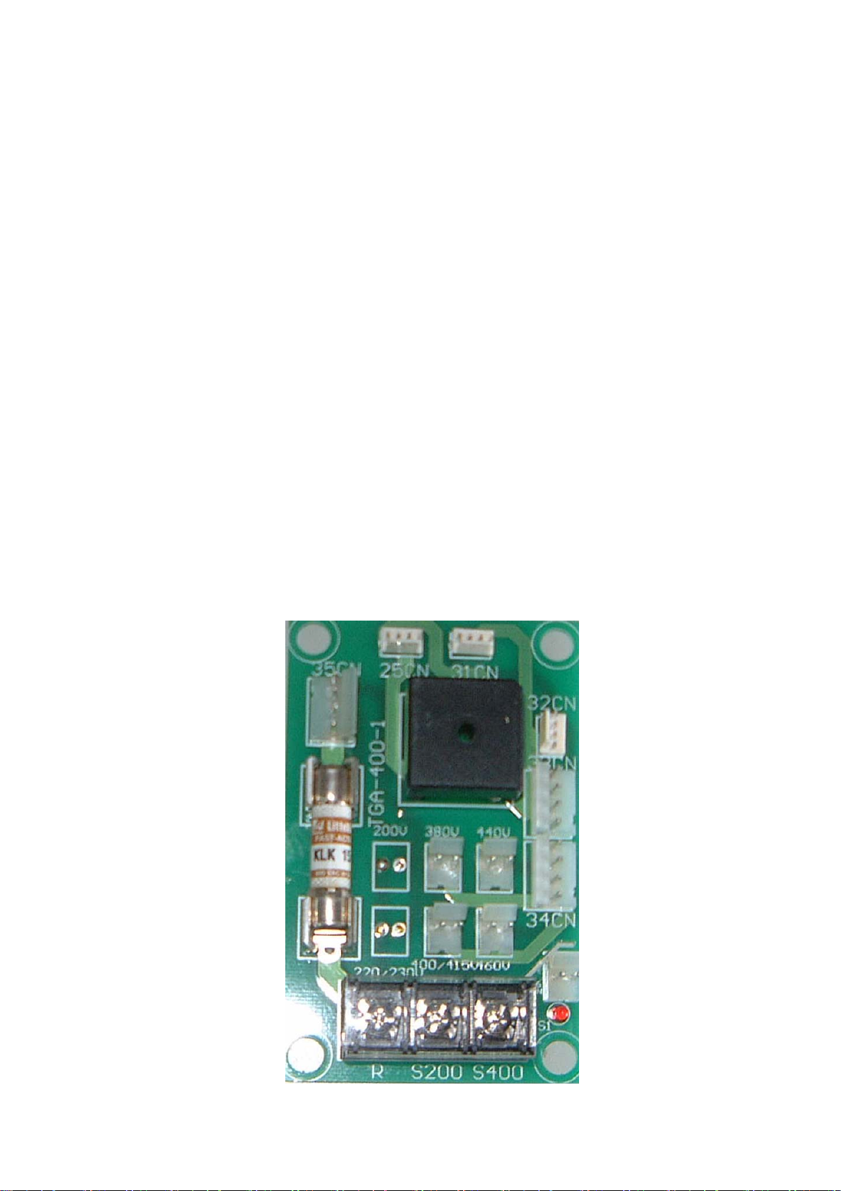
4.3 SETTING THE LINE VOLTAGE USING JUMPER
(FOR 440V CLASS 18.5kW AND ABOVE) ··················································································· 17
4.4 TEST RUN···························································································································· 18
5 SIMPLE DATA SETTING ·······················································································23
5.1 DIGTAL OPERATOR KEY DESCRIPTION ······································································· 23
5.2 LED DESCRIPTION ············································································································ 24
6 PROGRAMMING FEATURES ··············································································26
6.1 CONSTANT SET-UP AND INITALIZATION ·····································································26
6.2 V/F PATTERN SETTING ····································································································· 26
6.3 OPERATION CONDITIONS ······························································································· 29
6.4 STOPPING METHOD·········································································································· 43
6.5 INTERFACE CIRCUITS WITH EXTERNAL DEVICES···················································· 46
6.6 ADJUSTING MOTOR TORQUE························································································· 56
6.7 MOTOR PROTECTION······································································································· 57
6.8 PID CONTROL ····················································································································59
6.9 ENERGY SAVING CONTROL···························································································· 61
6.10 MODBUS CONTROL·········································································································· 63
2

7 MAINTENANCE AND INSPECTION ··································································64
7.1 PERIODIC INSPECTION ···································································································· 65
7.2 PARTS REPLACEMENT SCHEDULE (GUIDELINES)····················································· 65
8TROBULESHOOTING·····························································································66
8.1 FAULT DIAGNOSIS AND CORRECTIVE ACTIONS ·······················································66
8.2 ALARM DISPLAY AND EXPLANATION ·········································································69
8.3 MOTOR FAULTS AND CORRECTIVE ACTIONS ···························································· 70
APPENDIX 1 SPECIFICATIONS ·············································································71
APPENDIX 2 DIMENSIONS (mm)···········································································72
APPENDIX 3 TYPICAL CONNECTION DIAGRAM···········································73
3.1 BRAKING RESISTOR UNIT······························································································· 73
3.2 BRAKING UNIT AND BRAKING RESISTOR UNIT ························································ 74
APPENDIX 4 CONSTANT LIST···············································································75
APPENDIX 5 DIGT AL OPERATOR MONITOR DISPLAY ································81
BRAKING UNIT APPLICATION LIST···································································83
SEPARATELY -INSTALLED TYPE BRAKING RESISTOR································84
3
1. RECEIVING
SOURC
CAUTION
●Do not install or operate any inverter which is damaged or has missing parts.
Failure to observe this caution may result in personal injury or equipment damage
This chapter describes how to inspect the inverter after delivery to the user.
1.1 INSPECTION CHECKPOINTS
(1)Receiving Checkpoints
Checkpoints Description
Does the inverter model number correspon
the purchase order?
Are any parts damaged?
Check the model number on the nameplate on the
side of the TG-300
Visually check the exterior and verify that there
was no damage during transport.
Is hardware properly seated and securely
tightened?
Was an instruction manual received?
Remover inverter front cover.
Check all visible hardware with appropriate tools.
TG-300 instruction manual
If any of the above checkpoints are not satisfactory, contact your SHANGCHIN representative.
(2)Checking the Nameplate Data
(a)Nameplate Date
Example of TG-300
Model
TG 300 -
E V H z
CAPACITY kVA
Input power supply
Output capacity
Output power supply
Manuf. No.
VOLTS V CURRENTS A
SERIAL NO.
TOP GIN MADE IN TAIWAN
4
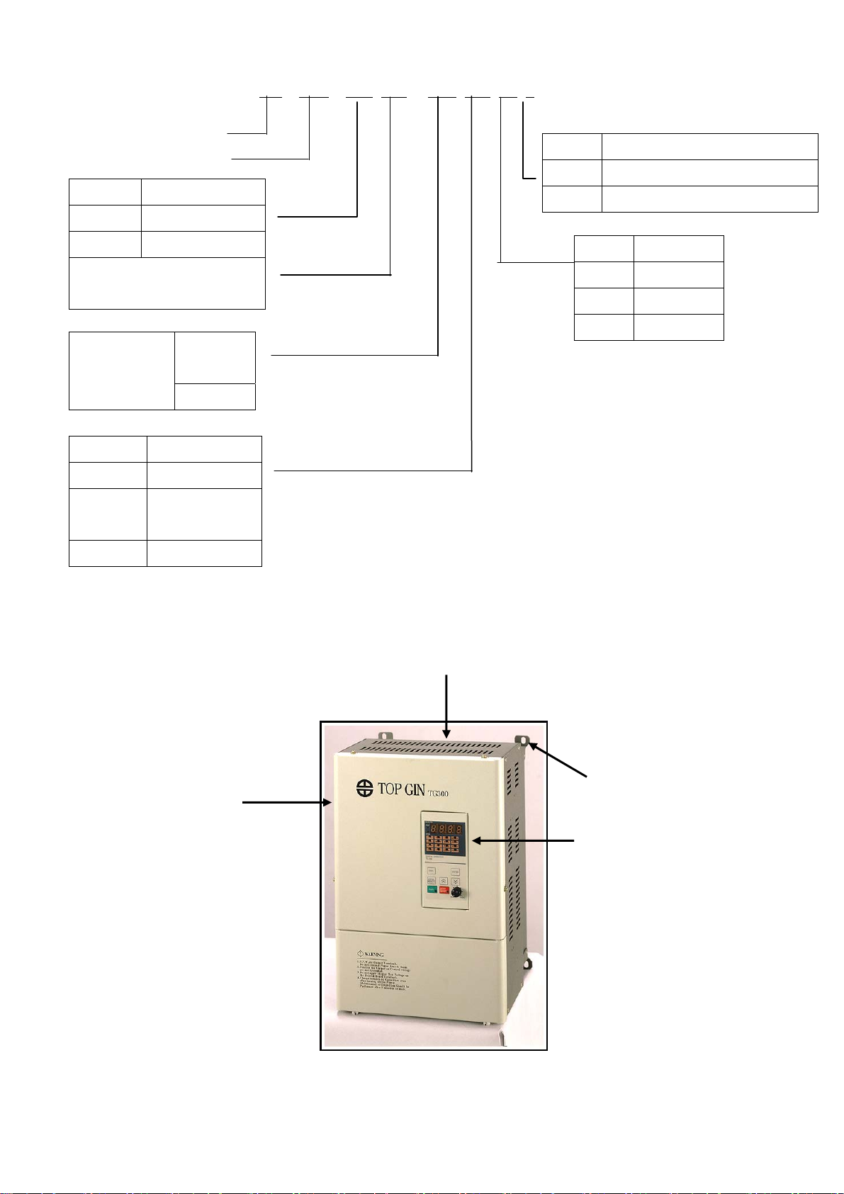
●Model Designation
TG – 300 – L 100 – A 2 T 1
TOP GIN
IGBT Series
Symbol Voltage
L
H
Max applicable motor
output (10Hp)
3φ220V Series
3φ440V Series
Symbol Enclosure
Braking
resitstor
A:
Without
B:With
Operator
1 Black
2 Digital with
VR
0 Open shdssis type (IP00)
1 Enclosed wall-mounted type(IP20)
Symbol Specification
T Standard
E CE mark
U UL
3 LCD with VR
1.2 IDENTIFYING THE PARTS
Front Cover
Protective Cover (top/bottom)
4 Mounting Holes
Digital Operator
Ventilation Slots
Flg. 4 Configuration of TG-300
5

2 . INSTALLATION
CAUTION
●Lift the cabinet by the base. When moving the unit, never lift by the front cover.
Otherwise, the main unit may be dropped causing damage to the unit.
●Mount the inverter on nonflammable material (i.e. metal).
Failure to observe this caution can result in a fire.
●When mounting units in an enclosure, install a fan or other cooling device to keep the intake air
temperature below 45℃.
Overheating may cause a fire or damage to the unit.
This chapter describes configuration, location and clearances when mounting the TG-300.
2.1 LOCATION FOR THE INVERTER
To ensure proper performance and long operating life, follow the recommendations below when
choosing a location for installing the TG-300. Make sure the inverter is protected from the following
conditions:
□ Extreme cold and heat.
□ Use only within ambient temperature range:-10℃ to +40℃
□ Rain, moisture. (For enclosed wall-mounted type)
□ Oil sprays, splashes
□ Salt spray
□ Direct sunlight. (Avoid using outdoors.)
□ Corrosive gases or liquids.
□ Dust or metallic particles in the air.(For enclosed wall-mounted type)
□ Physical shock, vibration.
□ Magnetic noise. (Example: welding machines, power devices, etc.)
□ High humidity.
□ Radioactive materials.
□ Combustibles:thinners, solvents, etc.
6
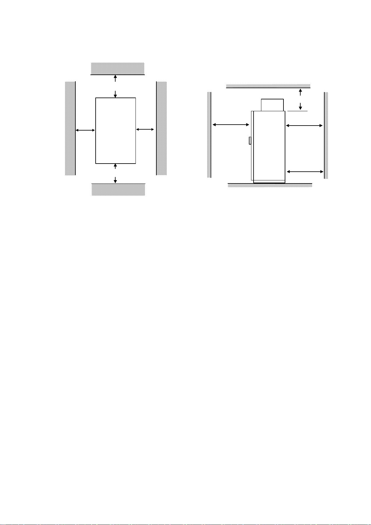
2.2 CLEARANCES
Install the TG-300 vertically and allow sufficient clearances for effective cooling as shown below.
Note:
150mm
Inverter
Front
face
100mm
150
500
Door width
50mm50mm
150
+ 100
500
For
front/rear
door
Door width
+ 100
1.The clearances required at top/bottom and both sides are common in open chassis type (IP00) and
enclosed wall-mounted type (IP20).
2.Remove the top and bottom covers to use the open chassis type of 220V/440V 15Kw or less.
3.For the external dimensions and mounting dimensions, refer to Appendix 2 “DIMENSIONS”.
4.Allowable intake air temperature to the inverter:
●Open chassis type :-10℃ to +45℃
●Enclosed wall-mounted type:-10℃ to +40℃
5. Ensure sufficient space for the sections at the upper and lower parts marked with * in order to permit
the flow of intake/exhaust air to/from the inverter.
7

3. WIRING
WA R IN G
●Only commence wiring after verifying that the power supply is turned OFF.
Failure to observe this warning can result in an electrical shock or a fire.
●Wiring should be performed only by qualified personnel.
Failure to observe this warning can result in an electrical shock or a fire.
●When wiring the emergency stop circuit, check the wiring thoroughly before operation.
Failure to observe this warning can result in personal injury.
CAUTION
●Verify that the inverter rated voltage coincides with the AC power supply voltage.
Failure to observe this warning can result in personal injure or a fire.
●Do not perform a withstand voltage test of the inverter.
It may cause semi-conductor elements to be damaged.
●To connect a braking resistor, braking resistor unit or braking unit, follow the procedures described
in APPENDIX 3.
Improper connection may cause a fire.
●Tighten terminal screws to the specified tightening torque.
Failure to observe this caution can result in a fire.
This chapter describes the main circuit wiring and the control circuit wiring of the TG-300.
8
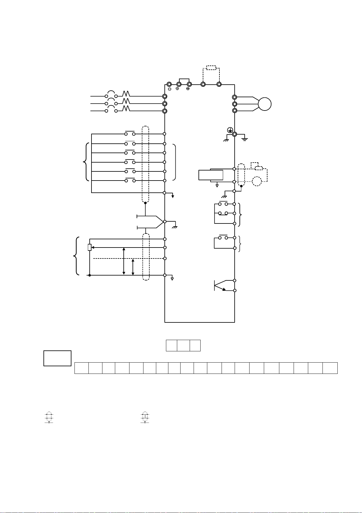
3.1 CONNECTION DIAGRAM
Below is connection diagram of the main circuit and control circuit. Using the digital operator, the
motor can be operated by wiring the main circuit only.
Breaking Resistor (Option)
3-Phase
Power Supply
200 to 240V
345 to 480V
50/60 HZ
Factory
Setting
Master
Frequency
Reference
MCCB
R
S
TL3(T)
Forward Run/Stop
Reverse Run/Stop
External Fault
Fault Reset
Multi-step Speed Setting 1
Multi-step Speed Setting 2
2kΩ
0 to +10V
4 to 20mA
0V
P
P
1
2
B1 B2
L1(R)
L2(S)
S1 Forward Run
when CLOSED
S2
S3
Multi-function
S4
Contact input
S5
S6
Sequence Commom
SC
Terminal (0V)
G
Shield Sheath
Connection
Terminal
Freq. Setting Power
FS
Supply +15V 20mA
FV
Master Freq. Ref.
0 to 10V (20kΩ)
FI
Master Freq. Ref.
4 to 20mA (250Ω)
[0 to 10V(20kΩ)input available]
FC
0V
Analog
Monitor
U(T1)
V(T2)
W(T3)
AM
AC
MA
MB
MC
M2
M3
TG 250
Motor
IM
Ground (100Ω or less)
Multi-function Analog Output 0
to +10V
+
-
(G)
Multi-function Contact Output
Contact Capacity:250 VAC 1A or less
30 VDC 1A or less
(Fault Output Signal at Factory Setting)
M1
Multi-function Contact Output
250 VAC 1A or less
30 VDC 1A or less
(Signal during Running at Factory Setting)
M4
OPEN COLLECTOR OUTPUT
(ZERO SPEED SIGNAL)
(OPTION)
(Output Frequency at Factory
FM
Setting)
TG 300
Connection Diagram
W2
ON OFF
G
S1 S2 S3 SC SC S4 S5 S6 FV FI FS FC AM AC M1 M2 MA MB MC
VR SET HZ W2 OFF
REMOTE SET HZ W2 ON
Note:
P
indicates shielded wires and
1.
indicates twisted-pair shielded wires.
2.Voltage or current input for the master frequency reference can be selected by constant H042.
Voltage reference input is preset at the factory.
3.Control circuit terminal FR of +15 V has a maximum output current capacity of 20 mA.
4.Multi-function analog output should be used for monitoring meters (e.g. output frequency meter)
and should not be used for feedback control system.
9

3.2 WIRING THE MAIN CIRCUIT
WA R NI N G
●Make sure to ground the ground terminal
(Ground resistance 220V class:100Ω or less. 440V class:10Ω or less)
Failure to observe this warning can result in an electrical shock or a fire.
CAUTION
●Never connect the AC main circuit power supply to output terminals U,V and W.
The inverter will be damaged and invalidate the guarantee.
(1)Wiring Precautions for Main Circuit Input
(a)Installation of Molded-case Circuit Breaker (MCCB)
Make sure to connect MCCBs of fuses between AC main circuit power supply and TG-300 input
terminals L1, L2 and L3 to protect wiring.
(b)Installation of Ground Fault Interrupter
When connecting a ground fault interrupter to input terminals L1, L2 and L3, select one that is not
affected by high frequency.
(c)Installation of Magnetic Contactor
Inverters can be used without a magnetic contactor (MC) installed at the power supply side. When
the main circuit power supply is shut OFF in the sequence, a magnetic contactor (MC) can be used
instead of a molded-case circuit breaker (MCCB). However, when a magnetic contactor is switched
OFF at the primary side, regenerative braking does not function and the motor coasts to a stop.
● The load can be operated/stopped by opening/closing the magnetic contactor at the primary side.
However, frequent switching may cause the inverter to malfunction.
● When using a braking resistor unit, use a sequencer to break power supply side on overload relay
trip contact. If the inverter malfunctions, the braking resistor unit may be burned out.
(d)Terminal Block Connection Sequence
Input power supply phases can be connected to any terminal regardless of the order of L1, L2 and L3
on the terminal block.
(e)Installation of AC Reactor
When connecting an inverter (220V/440V 15Kw or less) to a large capacity power supply
transformer (600Kva or more), or when switching a phase advancing capacitor, excessive peak
current flows in the input power supply circuit, which may damage the converter section. In such
cases, install a DC reactor (optional) between inverter 1 and 2 terminals or an AC reactor
(optional) on the input side. Installation or a reactor is effective for improvement of power factor on
the power supply side.
10

(f)Installation of Surge Suppressor
For inductive loads (magnetic contactors, magnetic relays, magnetic valves, solenoids, magnetic
brakes, etc.) connected near the inverter, use a surge suppressor simultaneously.
(g)Prohibition of Installation of Phase Advancing Capacitor
If a phase advancing capacitor or surge suppressor is connected in order to improve the power factor,
it may become overheated and damaged by inverter high harmonic components. Also, the inverter
may malfunction because of overcurrent.
(2)Wiring Precautions for Main Circuit Output
(a)Connection of Terminal Block and Load
Connect output terminals U, V and W to motor lead wires U, V and W. Verify that the motor rotates
in the forward direction (CCW:counterclockwise when viewed from the motor load side) with the
forward run command. If the motor rotation is incorrect, exchange any two of output terminals U,V
or W.
(b)Strict Prohibition of Connection of Input Power Supply to Output Terminals
Never connect input power supply to output terminals U, V and W.
(c)Strict Prohibition of Short Circuiting or Grounding of Output Circuit
Never touch the output circuit directly or put the output line in contact with the inverter case.
Otherwise, it may cause an electrical shock or grounding. In addition, never short circuit the output
line.
(d)Prohibition of Connection of Phase Advancing Capacitor or LC/RC Noise Fitter
Never connect a phase advancing capacitor or LC/RC noise, filter to the output circuit.
(e) Avoidance of Installation of Magnetic Starter
Do not connect a magnetic starter or magnetic contactor to the output, circuit.
If the load is connected while the inverter is running, the inverter overcurrent
protective circuit operates because of inrush current.
(f) Installation of Thermal Overload Relay
An electronic overload protective function is incorporated into the inverter.
However, connect a thermal overload relay when driving several motors with one inverter or when
using a multi-pole motor. When using a thermal overload relay, set inverter constant H033 to 0.
Additionally, for thermal overload relay, at 50Hz set the same rated current value as that described
on the motor nameplate, or at 60Hz 1.1 times larger than the rated current value described on the
motor nameplate.
11

(g) Wiring Distance between Inverter and Motor
If the total wiring distance between inverter and motor is excessively long and the inverter carrier
frequency (main transistor switching frequency) is high, harmonic leakage current from the cable
will adversely affect the inverter and peripheral devices.
If the wiring distance between inverter and motor is long, reduce the inverter carrier frequency as
described below. Carrier frequency can be set. by constant H050.
Wiring Distance between Inverter and Motor
Wiring Distance between
Up to 50m Up to 100m More than 100m
Inverter and Motor
Carrier Frequency
(Set value of constant H050)
15kHZ or less
(6)
10kHZ or less
(4)
5kHZ or less
(2)
(3)Grounding
●Ground resistance
220 V class:100Ω or less, 440 V class:10Ω or less
●Never ground TG-300 in common with welding machines, motors, or other large-current electrical
equipment. Run all the ground wires in a conduit separate from wires for large-current electrical
equipment.
●Use the ground wires described in tables below and keep the length as short as possible.
●When using several TG-300 units side by side, ground the units as shown below
(b)Acceptable(a)Acceptable
(c)Not Acceptable
Grounding of Three TG-300 Units
12

3.3 WIRING THE CONTROL CIRCUIT
The following table outlines the functions of the control circuit terminals
Wire according to each terminal function.
(1) Functions of Control Circuit Terminate
Control Circuit Terminals
Classification Terminal Signal Function Description Signal Level
S1 Forward run/stop
S2 Reverse run/stop
S3 External fault input
S4 Fault reset input
Sequence Input Signal
Analog Input Signal
Sequence Output Signal
S5
S6
SC
FS
FV
FI
FC
G
M1
M2
MA
MB
MC
AM Frequency meter output
AC Common
Analog
Output
Signal
Multi-step speed
reference 1
Multi-step speed
reference 2
Sequence control input
common terminal
+15V Power supply
output
Frequency reference
input (voltage)
Frequency reference
input (current)
Common terminal for
control circuit
Connection to shield
searth of signal lead
During running
(NO contact)
Fault contact output
(NO/NC contact)
Forward run when closed, stop
when open
Reverse run
when closed,
stop when open
Fault when
closed, normal
state when
open
Reset when
closed
Effective when
closed
Effective when
closed
For analog command +15V power
supply
0 to
+10V/100%
4 to
20mA/100%
Closed when
running
Fault when
closed between
terminals MA
and MC
Fault when
open between
terminals MB
and MC
0 to +
10V/100%
Freq.
Multi-function
contact inputs
(H035 to H039)
---
H042 = 0:FV
effective
H042 = 0:FI
effective
0V ---
--- ---
Multi-function
contact output
(H041)
Multi-function
contact output
(H040)
Multi-function
contact analog
monitor 1
(H048)
Photo-coupler
insolation
Input :+24VD
8mA
+15V
(Allowable
current 20mA
max.)
0 to +10V
(20 kΩ)
4 to 20mA
(250Ω)
Dry contact
Contact
capacity:
250VAC 1 A or
less
30VDC 1 A or
less
Dry contact
Contact
capacity:
250VAC 1 A or
less
30VDC 1 A or
less
0 to +10V 2mA
or less
13

(2) Wiring the Control Circuit Terminals
ON
Screwdriver Blade Width
Insert the wire into the lower part of the terminal block and connect it tightly with a screwdriver.
Wire sheath strip length must be 7 mm.
7mm
(3) Precautions on Control Circuit Wiring
●Separate control circuit wires from main circuit wires and other power cables to prevent erroneous
operation caused by noise interference.
●Use twisted shielded or twisicd-pair shielded wire for the control circuit line and connect the
shielded sheath to the inverter terminal G.
Wiring distance should be less than 50 m.
3.4 WIRING INSPECTION
After completing of installation and wiring, check for the following items. Never use
control circuit buzzer check-
□ Wiring is proper.
□ Wire clippings or screws are not left in the unit.
□ Screws are securely tightened.
□ Bare wire in the terminal does not contact other terminals
14

4 OPERATION
WA R NI N G
●Only turn ON the input power supply after replacing the front cover. Do not remove the cover
while current is flowing.
Failure to observe this warning can result in an electrical shock.
●When the retry function (H057) is selected, do not approach the inverter or the load, since it may
restart suddenly after being stopped.
(Construct machine system, so as to assure safety for personnel, even if the inverter should restart.)
Failure to observe this warning can result in personal injury.
●Since the stop button can be disabled by a function setting, install a separate emergency stop
switch.
Failure to observe this warning can result in personal injury.
CAUTION
●Never touch the heatsink or discharging resistor since the temperature is very high.
Failure to observe this caution can result in harmful burns to the body.
●Since it is easy to change operation speed from low to high speed, verify the safe working range of
the motor and machine before operation.
Failure to observe this caution can result in personal injury and machine damage
●Install a holding brake separately if necessary.
Failure to observe this caution can result in personal injury
●Do not change signals during operation.
The machine or the inverter may be damaged
●Ail the constants of the inverter have been preset at the factory. Do not change the settings
unnecessarily.
The inverter may be damaged. For supply voltage, follow Par. 4.3.
This chapter describes the basic operation procedures of the TG-300.
15

4 .1 OPERATION MODE SELECTION
The TG-300 has two operation modes, LOCAL and REMOTE, as described below. These two
modes can be selected by the digital operator "LOCAL/REMOTE" key only while the operation is
stopped. The selected operation mode can be verified by observing the digital operator SEQ and
REF LEDs as shown below. The operation mode is set to REMOTE (run by control circuit terminals
FV and FI frequency reference and run command from a control circuit terminal) prior to shipment.
Multi-function contact inputs from control circuit terminals S3 to S6 are enabled in both operation
modes LOCAL/REMOTE.
●LOCAL :Both frequency reference and run command are set by the digital operator. SEQ
and REF LEDs go OFF.
●REMOTE:Master frequency reference and run command can be selected as described below.
Reference Selection in REMOTE Mode (H002: Operation Method Selection)
Setting Operation Method Selection
0
1
2
3
4
Operation by run command from digital
operator
Operation by run command from control
circuit terminal ON
Operation by run command from digital
operator
Operation by run command from control
circuit terminal
Operation by run command from digital
operator
SEQ
LED
OFF
OFF
ON
OFF
Reference Selection
Master frequency reference
from digital operator
Master frequency reference
from
digital operator
Master frequency reference
from
control circuit terminals FV
and FI
Master frequency reference
from
control circuit terminals FV
and FI
Master frequency reference set
by serial communication
REF
LED
OFF
OFF
ON
ON
ON
5
6
7
8
Operation by run command from control
ON
circuit terminal
Operation by run command from serial
ON
communication
Operation by run command from serial
communication ON
Operation by run command from serial
communication
ON
Master frequency reference set
by serial communication
Master frequency reference set
by serial communication
Master frequency reference
from
digital operator
Master frequency reference
from
control circuit terminals FV
and FI
ON
ON
OFF
ON
16
4.2 TEST RUN CHECKPOINTS
To assure safety, prior to initial operation, disconnect the machine coupling so that the motor is
isolated from the machine. If initial operation must be performed while the motor is still coupled to
the machine, use great care to avoid potentially hazardous conditions. Check the following items
before a test run.
□ Wiring and terminal connections are correct.
□ No short circuit caused by wire clippings.
□ Screw-type terminals are securely tightened.
□ Motor is securely mounted.
□ All items are correctly earthed(grounded).
4.3 SETTING THE LINE VOLTAGE USING JUMPER
(FOR 440V CLASS 55kW AND ABOVE)
Set the line voltage jumper according to the main circuit power supply.
Insert the jumper at the appropriate location corresponding to the input line voltage
It has been preset at the factory to 440V.
Line Voltage Jumper (For 440V Class 55W to 300kW)
17
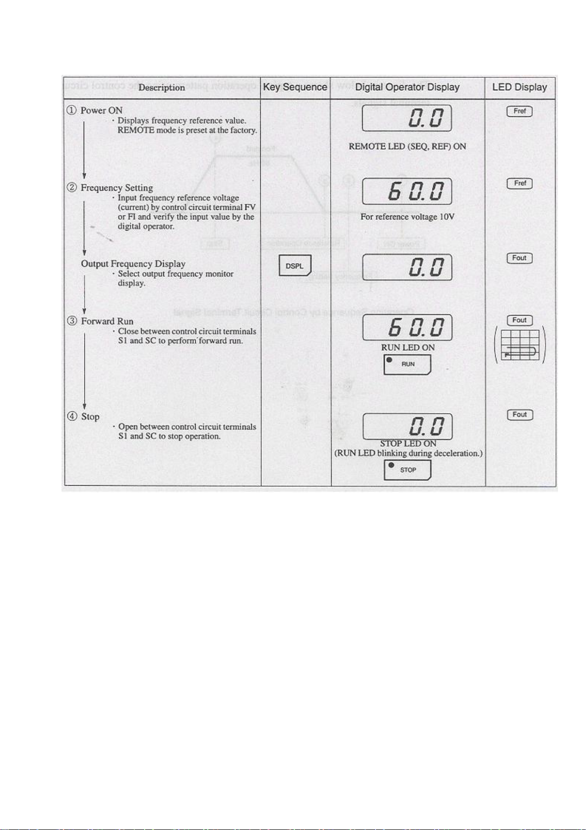
4.4 TEST RUN
(1) Digital Operator Display at Power-up
When the system is ready for operation, turn ON the power supply. Verify that the inverter powers
up properly. If any problems are found, turn OFF the power supply immediately. The digital operator
display illuminates as shown below
Digital Operator Display Digital Operator Display
LED LCD
18
(2) Operation Check Points
Check the following items during operation
□ Motor rotates smoothly.
□ Motor rotates in the correct direction.
□ Motor does not have abnormal vibration or noise.
□ Acceleration and deceleration are smooth.
□ Current matches the load flow.
□ Status indicator LEDs and digital operator display are correct
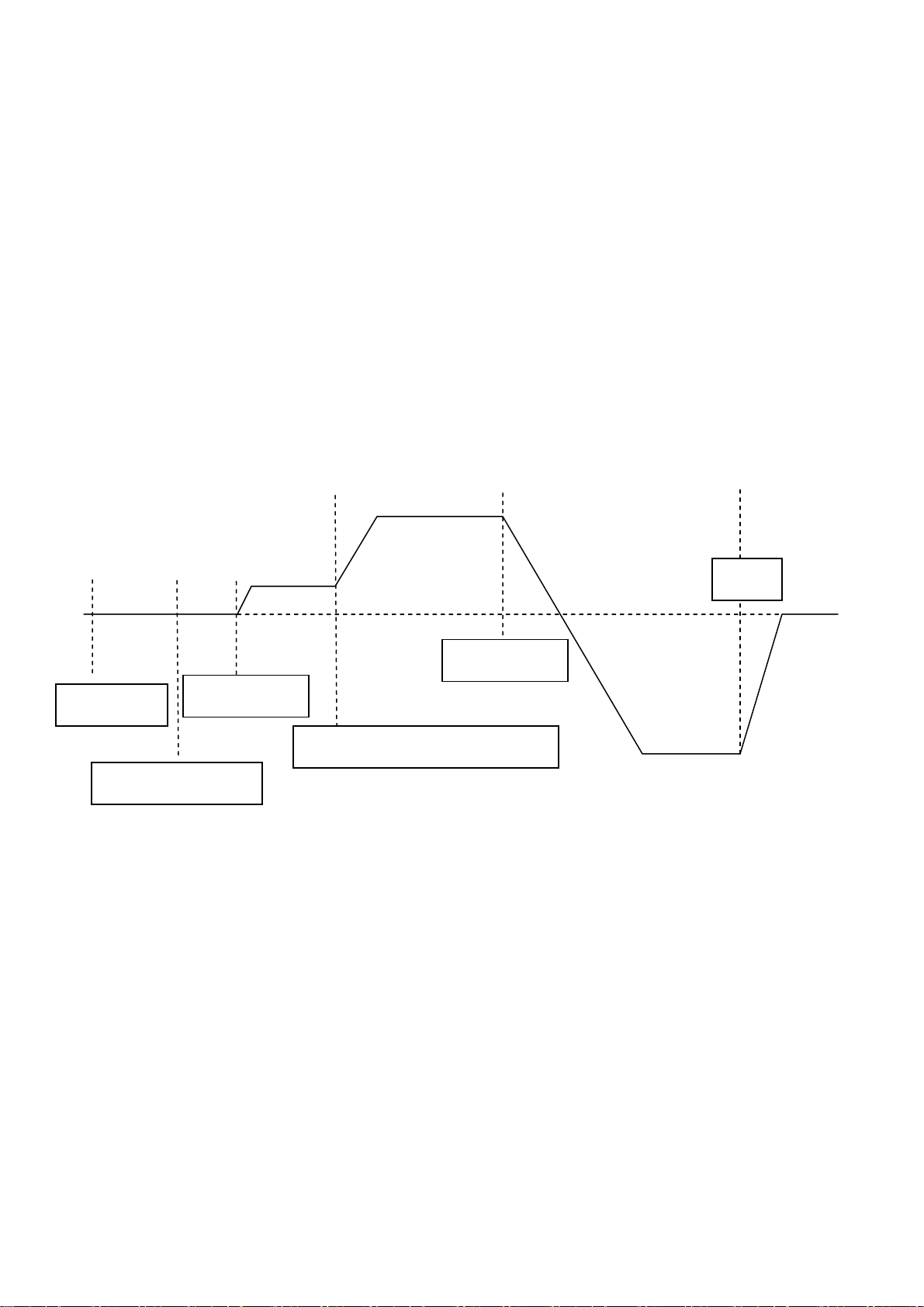
(3) Example of Basic Operation
(a) Operation by Digital Operator
The diagram below shows a typical operation pattern using the digital operator
f Forward g h
60 Hz
c d e Forward
25Hz
Power ON
Reverse
Forward Run
Frequency Reference Change
60 Hz
Frequency Setting
Operation Sequence by Digital Operator
Reverse Run
Stop
19
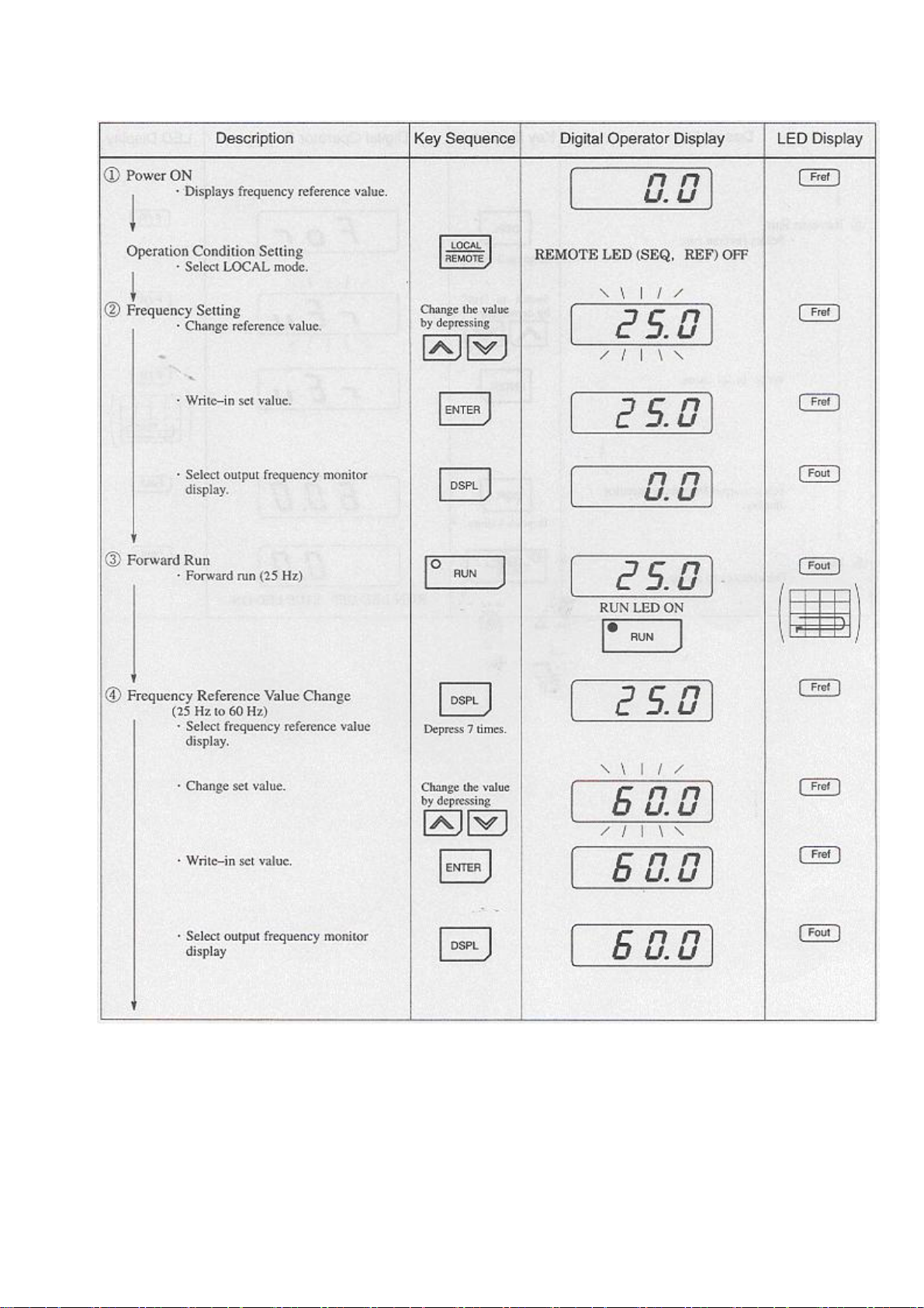
Typical Operation by Digital Operator
20
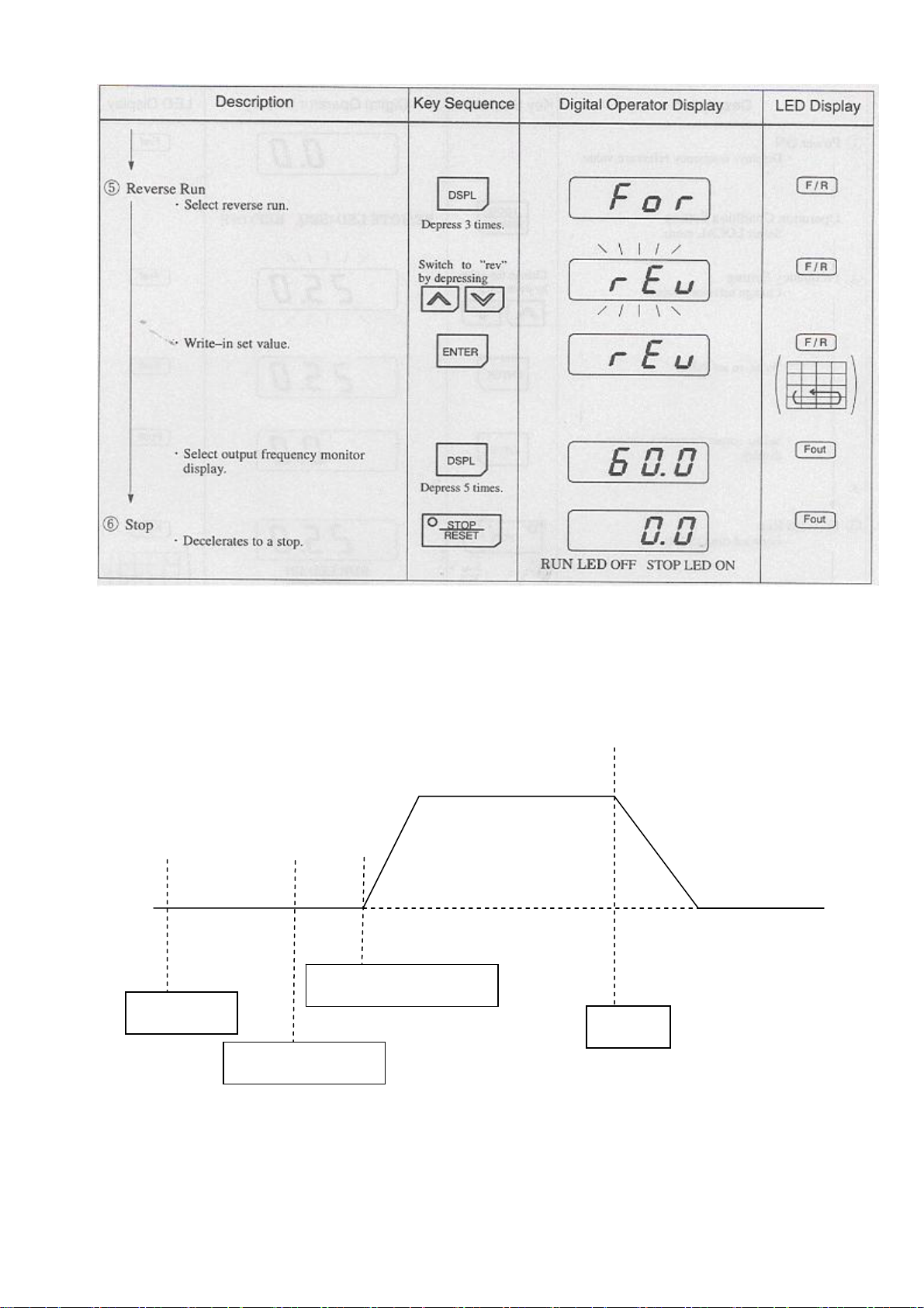
Typical Operation by Digital Operator (Cont’d)
(b)Operation by Control Circuit Terminal Signal
The diagram below shows a typical operation pattern using the control circuit terminal signals.
f
Forward
60 Hz
c d e
Power ON
Reference Operation
Stop
Frequency Setting
Operation Sequence by Control Circuit Terminal Signal
21
Typical Operation by Control Circuit Terminal Signal
22
5 SIMPLE DATA SETTING
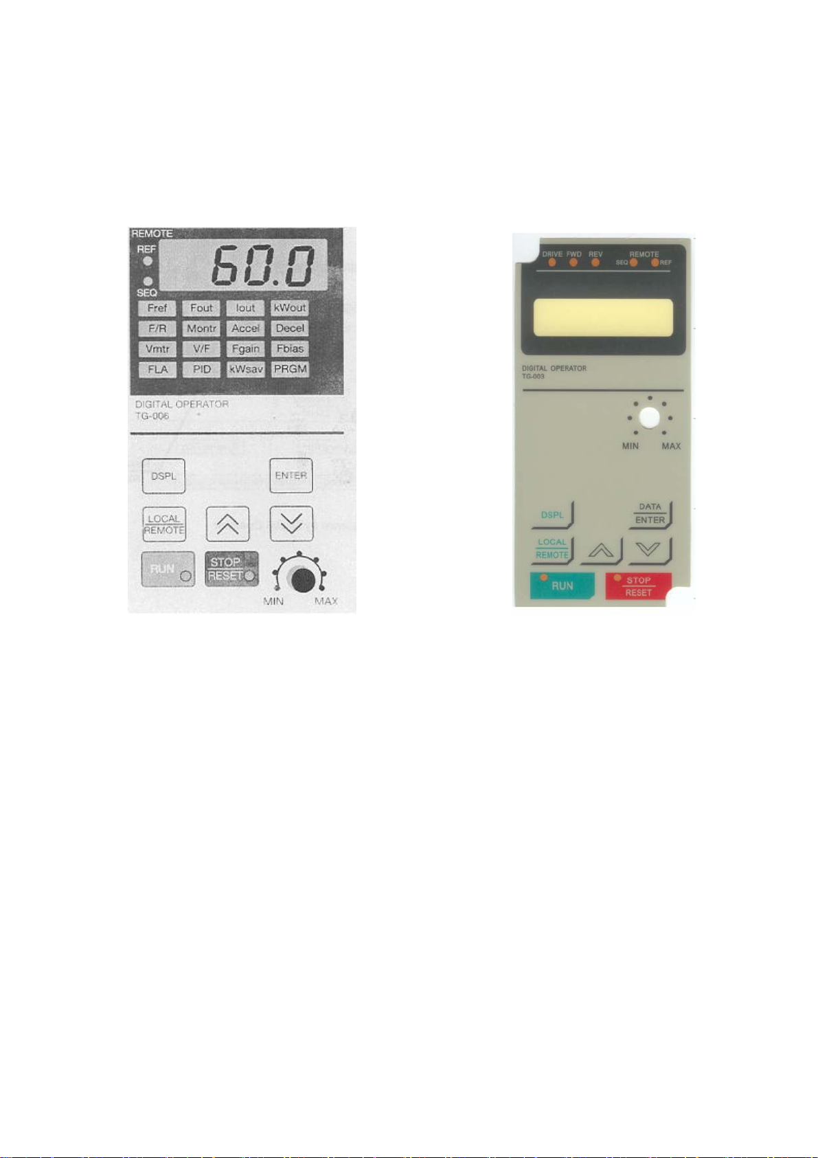
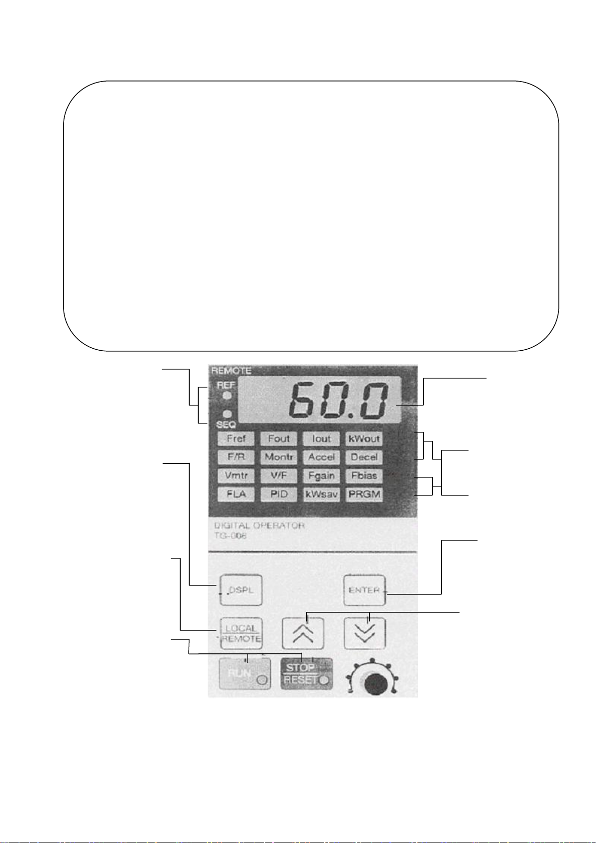
5.1 DIGITAL OPERAT KEY DESCRIPTION
Fref Fout Iout kwout
Frequency Output frequency Output current Output power
Reference monitor monitor monitor
Setting/monitoring
F/R Montr Accel Decel
FWD/REV run Monitor Acceleration Deceleration time
Command Selection Time
Selection
Vmtr V/F Fgain Fbias
Motor rated V/f pattern Frequency Frequency
Voltage selection Reference gain reference bias
FLA P/D Kwsalv PRGM
Motor rated current PID selection Energy saving
selection
Constant No/data
LED lights when inverter is controlled by
control circuit terminal commands.
SEQ:When RUN/STOP signal is through
terminals.
REF:When frequency reference is through
terminals.
Display Selection Key
Depressing this key changes the
display. See next page for
explanation
Operation Mode Selection Key
Mode Display LEDs
Depressing this key changes the mode
(LOCAL or REMOTE)
Operation Command Keys
Operation command keys operate the inverter.
Display
Displays the set value of each function and
monitor values such as output frequency and
output current (4 digits)
The selected function lights and allows changing
operation
Constants can be set only during a stop
Depressing this key recalls and
displays indicated data from
memory.
Depressing a second time enters the
displayed data into memory
Changes numbers such as set values
and constants
Λ:Increase Ⅴ:Decrease
Quick-Start LEDs
During Operation
Monitors/constants can be set during
During a Stop
Enter Key
Number Change keys
STOP/RESET Key:Stop command LED
Lights when STOP key is depressed. (It changes to
a reset key when a fault occurs.)
MIN MAX -----VR Set
RUN Key:Run command LED lights when the
RUN key is depressed.
23

5 .2 LED DESCRIPTION
By using the quick-start LEDs on the digital operator, simple operation of the inverter is possible.
Each quick-start LED is selected each time [DSPL] key is depressed. Following is a flowchart
describing quick-start LED selection. (Example of model TG-300-L50B2T)
24
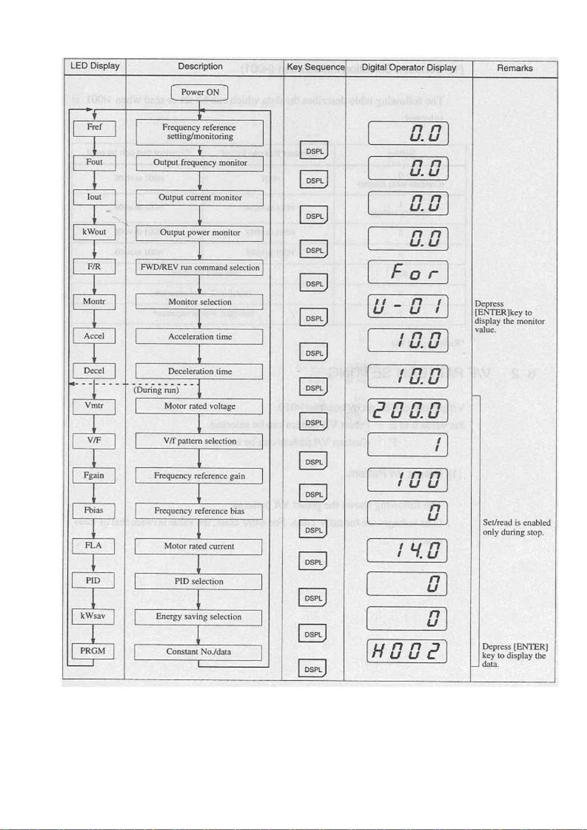
LED Description
25

6 PROGRAMMING FEATURES
6.1 CONSTANT SET-UP AND INITIALIZATION
(1) Constant Selection/Initialization (H001)
The following table describes the data which can be set or read when H001 is selected.
Setting Constant that can be set Constant that can be read
0
(Constant write disable)
1
(Factory setting)
2 H001 to H049 H001 to H108
3 H001 to H108 H001 to H108
4.5 Not used (disabled)
6
7
*Refer to page 60
6.2 V/F PATTERN SETTING
V/f pattern can be set by constant H010.
H001 H001 to H108
H001 to H034 H001 to H108
Initialize:2-wire sequence
Initialize:3-wire sequence*
Set value 0 to E:Preset V/f pattern can be selected
F:Custom V/f pattern can be set.
(1) Preset V/f Pattern
The following shows the preset V/f patterns.
(The voltages are for 220V class. For 440V class, the value is twice that of 220V class.)
26
 Loading...