

TOPENS ERM12 User Manual
User Manual of the Universal External Receiver
(Model: ERM12)
TOPENS Website
http://www.topenstool.com/
C030271 VER20a
Thank you for your purchasing ERM12 universal external receiver. It’s
compact, simple to operate and highly reliable.
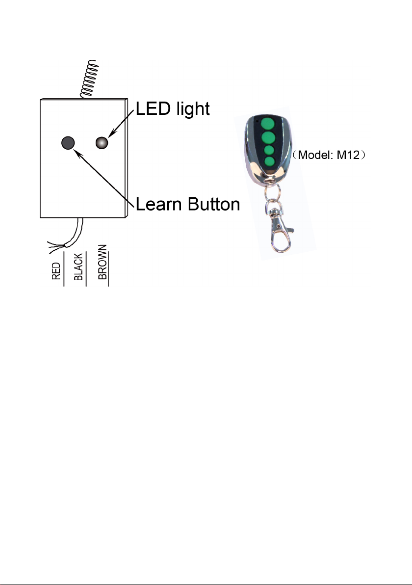
1. Definition of the wires:
RED: Positive of the power input. 9-24VDC+.
BLACK: Negative of the power input. 9-24VDC-.
BROWN: Signal output. Normally open to BLACK wire and temporary
closed (500mS) to BLACK wire when the receiver is activated.
2. Program the remote to the receiver:
Press and release the Learn button in receiver, the LED light will be ON,
then press the key in the remote twice in 4 seconds, the LED light will flash
for 3 seconds and then to OFF. Now the re mote has been programmed
successfully.
NOTE: Maximum 250PCS remotes can be programmed to the receiver.
3. Erase all Remote Codes:
Press and hold the Learn button until the LED light from ON to OFF. Now
all remote codes have been erased.
1
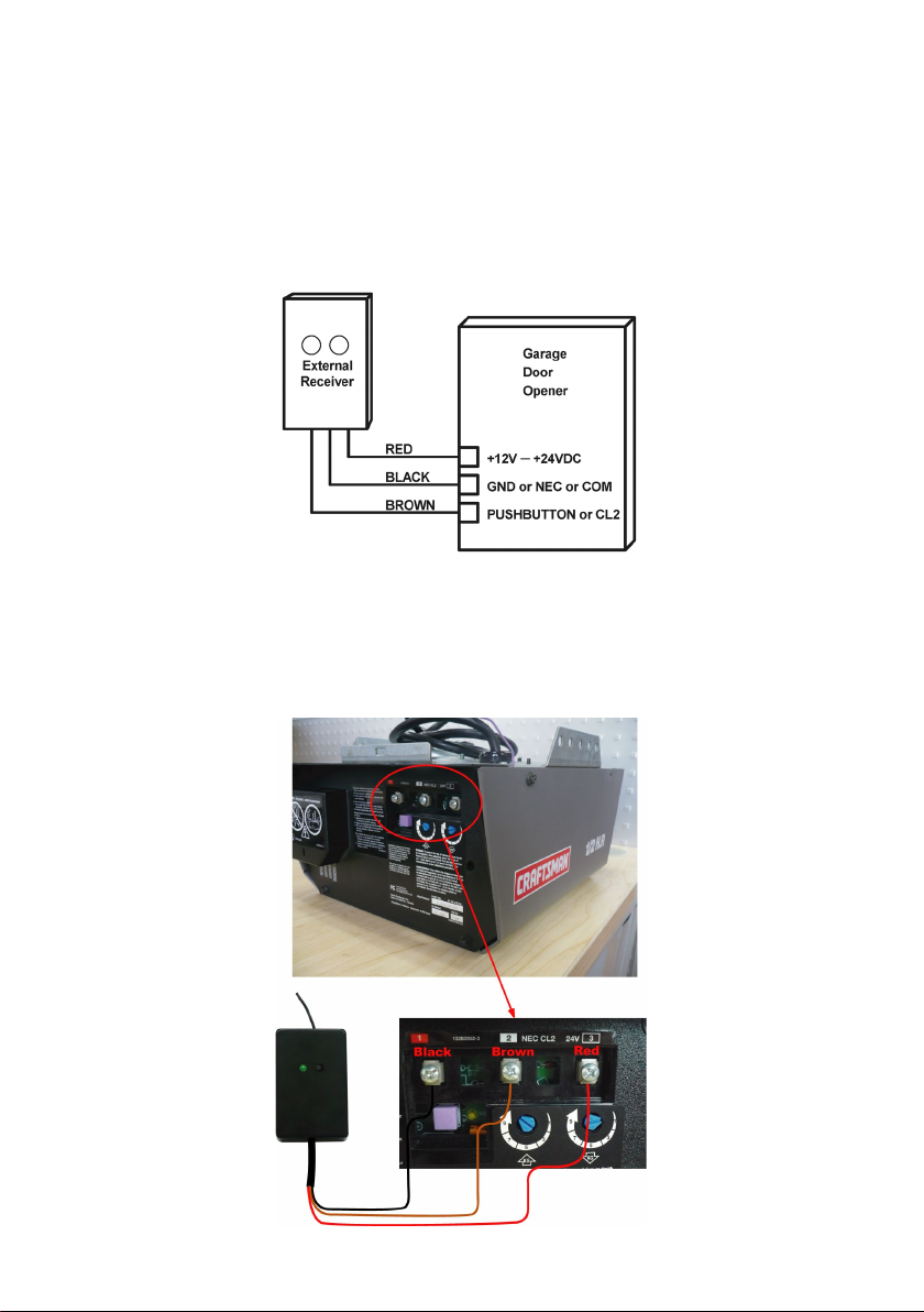
4. Wire connection:
For the TOPENS gate opener, please connect the receiver to the control
board refer to the chapter “Connection of the control board” of the user
manual of the gate opener.
4.1 Connect the external receiver to the door opener if it is with
Aux.9-24VDC output.
e.g. Connect the external receiver to CRAFTSMAN garage door opener.
(a). Connect the black wire into “NEC” terminal.
(b). Connect the brown wire into “CL2” terminal.
(c). Connect the red wire into “24V” terminal.
2
 Loading...