

Page 1
www.topconpa.com
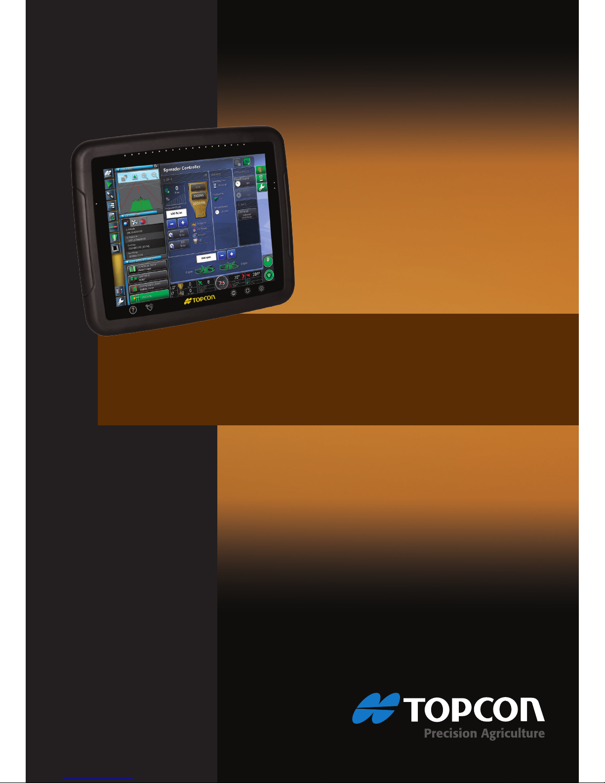
Spreader Controller
System 350
X30 Console
Operator’s Manual
Page 2

Page 3

X30 Spreader Controller
Operator’s Manual
Part Number: AGA4950-EN
Rev Number: 1.0
.1
For use with Software Version 3.12.12
© Copyright Topcon Precision Agriculture
August 2012
All contents in this manual are copyrighted by Topcon. All rights reserved. The information
contained herein may not be used, accessed, copied, stored, displayed, sold, modified, published
or distributed, or otherwise reproduced without express written consent from Topcon.
www.topconpa.com
Page 4
X30 Spreader Controller
0-1
Preface
This manual provides information about operating and
maintaining this Topcon Precision Agriculture product. Correct
use and servicing is important for safe and reliable operation of
the product.
It is very important that you take the time to read this manual
before using the product.
Information in this manual is current at the time of publication. A
system may vary slightly. The manufacturer reserves the right to
redesign and change the system as necessary without notification.
Alert Symbols
In this manual two alert symbols are used.
This offers additional information.
Warning: A warning signal appears on safety
signs and in this manual to show that this
information is very important to your safety.
LEARN these and APPLY them.
Page 5

X30 Spreader Controller
0-2
Terms and Conditions
Please read these Terms and Conditions carefully.
General
APPLICATION
- You accept these
Terms and Conditions by purchasing
the product from Topcon Precision
Agriculture (TPA) or from one
TPA’s product dealers.
COPYRIGHT
- All information
contained in this manual is the
intellectual property of, and
copyrighted material of TPA. All
rights are reserved. You may not use,
access, copy, store, display, create
derivative works of, sell, modify,
publish, distribute, or allow any third
parties access to, any graphics,
content, information or data in this
manual without TPA’s express
written consent and may only use
such information for the care and
operation of your product. The
information and data in this manual
are a valuable asset of TPA and are
developed by the expenditure of
considerable work, time and money,
and are the result of original
selection, coordination and
arrangement by TPA.
TRADEMARKS
– ZYNX,
PROSTEER, EAGLE, KEE
Technologies, Topcon, Topcon
Positioning Systems and Topcon
Precision Agriculture are trademarks
or registered trademarks of the
Topcon Group of companies.
Microsoft and Windows are
trademarks or registered trademarks
in the United States and/or other
countries of Microsoft Corporation.
Product and company names
mentioned herein may be trademarks
of their respective owners.
WEBSITE AND OTHER
STATEMENTS
- No statement
contained at the website of TPA or
any other Topcon Group company or
in any other advertisements or TPA
literature or made by an employee or
independent contractor of TPA
modifies these Terms and
Conditions.
IMPORTANT: SAFETY
- Improper
use of the product can lead to death
or injury to persons, damage to
property and/or malfunction of the
product. The product should only be
repaired by authorized TPA service
centers. You should closely review
the safety warnings and directions as
to the proper use of the product in
this manual and at all times comply
with the same.
Limited Warranty
ELECTRONIC AND
MECHANICAL COMPONENTS
-
TPA warrants that the electronic
components manufactured by TPA
shall be free of defects in materials
and workmanship for a period of one
year from the original date of
shipment to the dealer. TPA
Page 6

X30 Spreader Controller
0-3
warrants that all valves, hoses, cables
and mechanical parts manufactured
by TPA shall be free of defects in
materials and workmanship for a
period of one year from the date of
purchase.
RETURN AND REPAIR - During
the respective warranty periods, any
of the above items found defective
may be shipped to TPA for repair.
TPA will promptly repair or replace
the defective item at no charge, and
ship it back to you. You must pay the
shipping and handling charges in
respect of the same. Calibration of
components, labor and travel
expenses incurred for in-field
removal and replacement of
components are not covered in this
warranty policy. The foregoing
warranty shall NOT apply to damage
or defects resulting from:
(i) disaster, accident or abuse
(ii) normal wear and tear
(iii) improper use and/or
maintenance
(iv) unauthorized modifications of
the product; and/or
(v) use of the product in
combination with other products
not supplied or specified by
TPA.
Software accompanying any product
is licensed for use in connection with
the product and not sold. Use of
software that is provided with a
separate end user license agreement
(“EULA”) will be subject to the
terms and conditions, including those
relating to limited warranty, of the
applicable EULA, notwithstanding
anything in these Terms and
Conditions to the contrary.
WARRANTY DISCLAIMER -
OTHER THAN FOR THE ABOVE
WARRANTIES, WARRANTIES
PROVIDED IN AN APPLICABLE
WARRANTY CARD, APPENDIX
OR END USER LICENSE
AGREEMENT, THIS MANUAL,
THE PRODUCT AND RELATED
SOFTWARE ARE PROVIDE ‘ASIS’. THERE ARE NO OTHER
WARRANTIES AND TO THE
EXTENT ALLOWED BY LAW TPA
EXCLUDES ALL IMPLIED
TERMS, CONDITIONS AND
WARRANTIES IN RESPECT OF
THE MANUAL AND THE
PRODUCT (INCLUDING ANY
IMPLIED WARRANTY OR
MERCHANTABILITY OR
FITNESS FOR ANY PARTICULAR
USE OR PURPOSE). TPA IS NOT
RESPONSIBLE FOR THE
OPERATION OF GNSS
SATELLITES AND/OR
AVAILABILITY, CONTINUITY,
ACCURACY, OR INTEGRITY OF
GNSS SATELLITE SIGNALS.
LIABILITY LIMIT AND
INDEMNITY - TPA and its dealers,
agents and representatives shall not
be liable for technical or editorial
errors or omissions contained herein
or for special, indirect, economic,
incidental or consequential damages
resulting from the furnishing,
performance or use of this material,
the product or its accompanying
software (including where TPA has
been advised of the possibility of
such damage). Such disclaimed
damages include but are not limited
to loss of time, loss or destruction of
data, loss of profit, savings or
revenue or loss of or damage to the
product. You shall defend,
indemnify and hold TPA harmless
from and against any claims, actions,
suits, damages, losses, liabilities and
Page 7

X30 Spreader Controller
0-4
costs (including attorneys’ fees)
arising from, or relating to (a) your
operation use, or maintenance of the
product and/or software other than as
provided for in this manual or the
applicable end user license
agreement; and (b) your negligence
or wrongful act or omission in
respect of the product.
In any event, TPA’s liability to you
or any other person for any claim,
loss or damage (in contract, tort or
on any other basis) will be limited
(in TPA’s option) to either (a) the
replacement or repair of the product,
or (b) payment of the cost of
replacing or repairing the product.
Other
These Terms and Conditions may be
amended, modified, superseded or
cancelled, at any time by TPA.
These Terms and Conditions will be
governed by, and construed in
accordance with:
- the laws of South Australia if the
product is sold and supplied to
you in Australia (in which case
the courts of South Australia or
the Federal Court of Australia
(Adelaide Registry) have
exclusive jurisdiction in respect
of any claim or dispute) or
- the laws of the State of California
if the product is sold and supplied
to you outside of Australia
- the provisions of the United
Nations Convention on Contracts
for the International Sale of
Goods shall not apply to these
Terms and Conditions.
All information, illustrations, and
applications contained herein are
based on the latest available
information at the time of
publication. TPA reserves the right
to make product changes at any time
without notice.
If any part of these Terms and
Conditions would be unenforceable,
the provision must be read down to
the extent necessary to avoid that
result, and if the provision cannot be
read down to that extent, it must be
severed without affecting the validity
and enforceability of the remainder
of these Terms and Conditions.
Service Information
Service assistance can be provided
by contacting your local TPA
Authorized Dealer.
Page 8
X30 Spreader Controller
0-5
Communications Regulation Information
FCC Compliance Statement (USA)
This equipment has been tested and found to comply with
the limits for a Class ‘A’ digital device, pursuant to Part
15 of the FCC Rules. Operation of this equipment in a
residential area is likely to cause harmful interference in
which case the user will be required to correct the
interference at the user's expense.
FCC Compliance Statement (Canada)
This Class A digital apparatus meets all requirements of
the Canadian Interference-Causing Equipment
Regulation.
CE EMC Statement (European Community)
Warning: This is a class ‘A’ product. In a domestic
environment this product may cause radio interference in
which case the user may be required to take adequate
measures.
‘C’ Tick EMC Statement (Australia & New Zealand)
This product meets the applicable requirements of the
Australia and New Zealand EMC Framework.
Type Approval and Safety Regulations
Type approval may be required in some countries to license the
use of transmitters on certain band frequencies. Check with local
authorities and your dealer. Unauthorized modification of the
equipment may void that approval, the warranty and the license to
use the equipment.
The receiver contains internal radio-modem. This can potentially
send signals. Regulations vary between countries, so check with
the dealer and local regulators for information on licensed and
unlicensed frequencies. Some may involve subscriptions.
Page 9

X30 Spreader Controller
0-6
Radio and Television Interference
This computer equipment generates, uses, and can radiate radiofrequency energy. If it is not installed and used correctly in strict
accordance with Topcon Precision Agriculture instructions, it
may cause interference with radio communication.
You can check if interference is being caused by this equipment
by turning the Topcon equipment off to see if the interference
stops. If the equipment is causing interference to a radio or other
electronic device, try:
Turning the radio antenna until the interference stops
Moving the equipment to either side of the radio or other
electronic device
Moving the equipment farther away from the radio or other
electronic device
Connecting the equipment to another circuit that is not linked
to the radio.
To reduce potential interference, operate the equipment at the
lowest gain level that will allow successful communication.
If necessary contact your nearest Topcon Precision Agriculture
dealer for assistance.
Changes or modifications to this product not authorized by
Topcon Precision Agriculture could void the EMC
compliance and negate authority to operate the product.
This product was tested for EMC compliance using Topcon
Precision Agriculture peripheral devices, shielded cables
and connectors. It is important to use Topcon Precision
Agriculture devices between system components to reduce
the possibility of interference with other devices.
Page 10

X30 Spreader Controller
0-7
General Safety
DANGER: It is essential that the following
information and the product specific safety
information is read and understood.
Most incidents arising during operation, maintenance and repair
are caused by a failure to observe basic safety rules or
precautions. Always be alert to potential hazards and hazardous
situations.
Always follow the instructions that accompany a Warning or
Caution. The information these provide aims to minimize risk of
injury and/or damage to property.
In particular follow instructions presented as Safety Messages.
Safety Messages and Warnings
The safety symbol is used with the relevant word: DANGER,
WARNING or CAUTION.
Messages marked in this way recommend safety precautions and
practices. LEARN and apply them.
DANGER: Indicates an imminently hazardous
situation that, if not avoided, could result in DEATH
OR VERY SERIOUS INJURY.
WARNING: Indicates a potentially hazardous
situation that, if not avoided, could result in DEATH
OR SERIOUS INJURY.
CAUTION: Indicates a potentially hazardous
situation that, if not avoided, may result in MINOR
INJURY.
Page 11
X30 Spreader Controller
0-8
Safety Signs
WARNING: DO NOT remove or obscure safety signs.
Replace any safety signs that are not readable or are
missing. Replacement signs are available from your
dealer in the event of loss or damage.
If a used vehicle has been purchased, make sure all safety signs
are in the correct location and can be read. Replace any safety
signs that cannot be read or are missing. Replacement safety signs
are available from your dealer.
Operator Safety
WARNING: It is YOUR responsibility to read and
understand the safety sections in this book before
operating this vehicle. Remember that YOU are the
key to safety.
Good safety practices not only protect you, but also the people
around you. Study this manual as part of your safety program.
This safety information only relates to Topcon equipment and
does not replace other usual safe work practices.
WARNING: In some of the illustrations or photos
used in this manual, panels or guards may have
been removed for demonstration purposes. Never
operate the vehicle with any panels or guards
removed. If the removal of panels or guards is
necessary to make a repair, these MUST be replaced
before operation.
Warning: Always check that any suspended vehicle
attachments are lowered to the ground before
beginning repair or maintenance work on a vehicle.
Page 12
X30 Spreader Controller
0-9
Warning: Vehicle and implement parts can become
hot during operation and may be under pressure.
Refer to vehicle manuals.
Warning: Wear appropriate protective clothing for
the task being undertaken and conditions.
Warning: Do not operate equipment around
explosive equipment or supplies.
Warning: Topcon is committed to good
environmental performance and minimizes the use
of any potentially harmful substances in its products.
However, it is always advisable not to handle
damaged electronic equipment.
This Topcon product may contain a sealed lithium
battery.
Always dispose of any electronic equipment
thoughtfully and responsibly.
Page 13
X30 Spreader Controller
0-10
Exposure to Radio Frequency
Exposure to energy from radio frequencies is an important safety
issue. Keep a distance of at least 20 cm (7.8 inches) between
people and any radiating antenna. Keep a distance of at least 20
cm between transmitting antennas.
Warning: Products using cellular modem or an
RTK base station can transmit radio frequency
energy. Check with your dealer.
This device is designed to operate with TPA approved antennas.
Discuss with your dealer.
Preparation for Operation
Read and understand this manual and learn all of the controls
before you use the equipment.
Keep the manual with the equipment.
If the equipment is moved to another vehicle, move the
manual as well.
Read the manual for the vehicle with which the equipment
will be used and check that the vehicle has the correct
equipment required by local regulations.
Make sure you understand the speed, brakes, steering,
stability, and load characteristics of the vehicle before you
start.
Check all controls in an area clear of people and obstacles
before starting work.
Identify possible hazards.
Warning: Topcon equipment must not be used by an
operator affected by alcohol or drugs. Seek medical
advice if using prescription or over-the-counter
Page 14

X30 Spreader Controller
0-11
medication.
Disclaimer
Topcon accepts no responsibility or liability for damages to
property, personal injuries, or death resulting from the misuse or
abuse of any of its products.
Further, Topcon accepts no responsibility for the use of Topcon
equipment or the GNSS signal for any purpose other than the
intended purpose.
Topcon cannot guarantee the accuracy, integrity, continuity, or
availability of the GNSS signal.
The operator must ensure that the equipment is correctly turned
off when not in use.
Before operating any vehicle equipped with Topcon products,
read and understand the following product specific safety
precautions.
Page 15

X30 Spreader Controller
0-12
X30 Important Safety Information
Operator Alertness and Responsibility
The X30 helps the operator to steer the vehicle, but the operator
remains in charge and must be alert and in complete control of the
vehicle at all times. The operator is ultimately responsible for safe
operation of this equipment.
It is essential that safety requirements are met when operating the
X30 and any of its components. All operators and other relevant
personnel must be advised of safety requirements.
Electrical Safety
Warning: Incorrectly connected power can cause
severe injury and damage to people or the
equipment.
When working with electrical components, you must do the
following:
Make sure the negative terminal of the battery is
disconnected before doing any welding on the vehicle.
Check that all power cables to system components are
connected to the correct polarity as marked. Please refer to
the vehicle manual for safety information.
Check that equipment is grounded in accordance with
installation instructions.
Operation and Risk of Obstacles
The following list is not exhaustive or limited. To use the X30 for
assisted steering along a defined wayline, the operator must
ensure that it is used:
Away from people and obstacles
Page 16

X30 Spreader Controller
0-13
Away from high voltage power lines or other overhead
obstructions (identify any clearance problems before
activating the X30)
On private property without public access
Within cleared fields
Off public roads or access ways.
Note that:
The operator needs to know the vehicle’s position and the
field conditions at all times.
The operator will need to respond if the GNSS satellite or
differential correction signal is lost momentarily.
The X30 cannot detect obstacles (people, livestock or other).
Only use the X30 in areas that are clear of obstacles and keep
a proper distance.
Steering needs to be disengaged for manual control if an
obstacle appears in the path or the vehicle moves away from
the wayline.
On/Off and Manual Control
Warning: Ensure the steering switch is in the Off
position to prevent unintentional engagement of
the assisted steering. When repairing or
maintaining the vehicle/implement, ensure the
vehicle CANNOT be moved. Disengage steering,
apply brakes and remove keys.
The operator must ensure that the steering switch is in the Off
position (all LED indicators are off) when assisted steering is not
being used.
Page 17

X30 Spreader Controller
0-14
The operator must disengage assisted steering and use manual
control if an obstacle is in the line of travel or moves into the line
of travel, or if the vehicle steers away from the desired wayline.
To disengage assisted steering:
Turn the steering wheel a few degrees OR
Select the Disengage Auto Steering button on the console
AND/OR
Move the steering switch to the OFF position if the above
actions do not disengage assisted steering.
Vehicle Shut Down Safety
Before leaving the vehicle, disengage assisted steering, turn the
steering switch to the OFF position, and remove the key from the
key switch.
Using a Reference (Base) Station
WARNING: Do not move a reference station
while in operation. Moving an operating reference
station can interfere with the controlled steering of
a system using the reference station. This could
result in personal injury or damage to property.
Operators and other affected personnel must be advised of the
following safety precautions.
Do not erect the reference station under or within the vicinity
of high voltage power lines.
When using the portable reference station, make sure that the
tripod is securely mounted.
Page 18

X30 Spreader Controller
0-15
To Get the Best Out of the Product
Back up data regularly. The console has large, but limited storage
capacity. Use the Diagnostics Mini-view to view capacity
available. A warning screen displays if storage is reaching its
limit.
Be aware of file format compatibility. Discuss compatible formats
with the dealer.
Topcon Agricultural Products are hardy and designed to work in
tough conditions. However, should equipment be unused for a
length of time, store away from water and direct heat sources.
Page 19

X30 Spreader Controller
0-16
Table of Contents
Chapter 1 - Introduction .......................................................... 1-1
Chapter 2 - Implement Setup .................................................. 2-1
2.1 Setting up a New Implement ............................................................................... 2-2
2.2 Connecting to ECUs ............................................................................................ 2-5
2.3 Setting up the ECU ............................................................................................. 2-6
2.4 Setting up Implement Geometry ....................................................................... 2-13
2.5 Setting up Section Control ................................................................................ 2-15
2.5.1 Setting On Time and Off Time .................................................................. 2-15
2.5.2 Setting up the Switch Box ......................................................................... 2-17
2.6 Enabling Auto Section Control ......................................................................... 2-18
Chapter 3 - Spreader Controller Setup .................................. 3-1
3.1 Setting up Spreader Controller ............................................................................ 3-2
3.2 Setting up Actuator ............................................................................................. 3-4
3.3 Setting up Control Valve (Proportional) ............................................................. 3-9
3.4 Setting up Bin Control Valve (Regulator) ........................................................ 3-14
3.5 Setting up Spinners ........................................................................................... 3-19
3.6 Setting Spinner Control Valves ......................................................................... 3-23
3.7 Setting up the Wheel Sensor ............................................................................. 3-27
3.8 Setting Alarms ................................................................................................... 3-28
Chapter 4 - Operations ............................................................ 4-1
4.1 Using the Spreader Dashboard ............................................................................ 4-2
4.2 Opening Auto Section Control ............................................................................ 4-4
4.3 Opening Spreader Controller .............................................................................. 4-7
4.4 Choosing / Changing Bins and Rates .................................................................. 4-9
4.5 Choosing / Changing a Product and Rate ......................................................... 4-10
4.6 Monitoring Statistics ......................................................................................... 4-16
4.7 Choosing and Changing Sub Areas .................................................................. 4-17
4.8 Configuring and Calibrating ............................................................................. 4-19
4.9 Managing the Spinners ...................................................................................... 4-21
4.10 Using the Master Switch ................................................................................. 4-22
4.11 Using Map Views and Layers ......................................................................... 4-23
Chapter 5 - Variable Rate Control ......................................... 5-1
5.1 Loading VRC Map Files ..................................................................................... 5-2
5.2 Using Variable Rate Control ............................................................................... 5-8
5.3 Downloading VRC Map Files with AgJunction ............................................... 5-10
Appendix A – Start up Checklist
Page 20

X30 Spreader Controller
1-1
Chapter 1 - Introduction
The X30 Spreader and Auto Section Controller is used with
the X30 Guidance and Auto Steering Console. Refer also to
the X30 Guidance and Auto Steering Operator's Manual.
The X30 Spreader Controller allows better control of the
amount of product being applied to a field. Once set up, it
will adjust the discharge rate according to vehicle speed and
the section being covered to maintain the preset application
rate. This provides more accurate use of a product over the
specified areas.
Auto Section Control minimizes wastage, turning parts of the
spreader on and off as the equipment passes through the
defined areas. The system will turn on when it detects an area
that has not been covered and it will turn off when it detects
areas that have already had product applied.
Section control is limited to the number of spinners being
controlled by the X30 Spreader Controller. In a two spinner
setup, there can be two sections (left and right). In a single
spinner setup, there is only one section which is the entire
working width of the spreader.
Regional information such as time and product
measurement units can be set by selecting User from the
Main Setup Menu
. Refer to the X30 Guidance and
Auto Steering Manual.
The console will ask you to confirm your selections:
Confirm the selection/action to continue.
Cancel the selection/action and return to previous screen.
Page 21
X30 Spreader Controller
2-1
Chapter 2 - Implement Setup
This chapter explains how to setup and configure the X30
Console for use with the Spreader Controller features. The
Spreader Controller option is only available when the
Electronic Control Units (ECUs) have been set up.
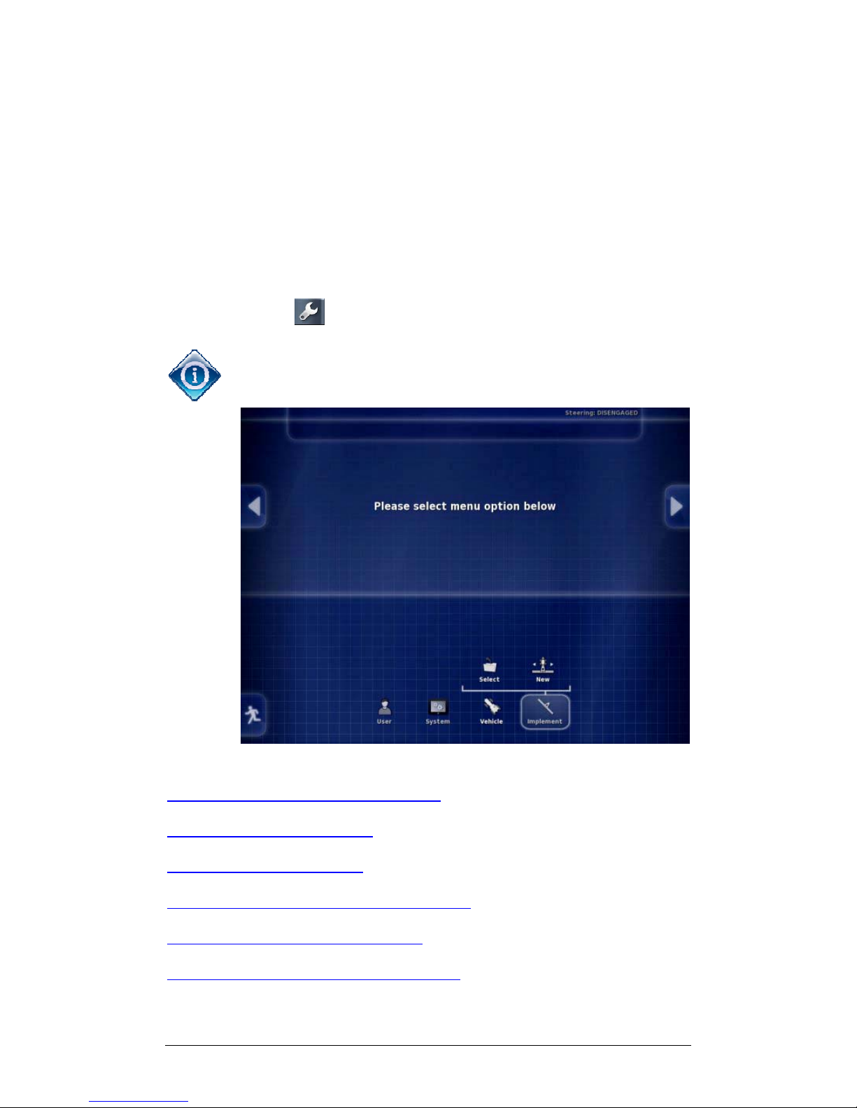
To return to the X30 Main Setup screen from operations
screens, select .
Note that when the system is new, the following
X30
Main Setup
screen will appear.
2.1 Setting up a New Implement
2.2 Connecting to ECUs
2.3 Setting up the ECU
2.4 Setting up Implement Geometry
2.5 Setting up Section Control
2.6 Enabling Auto Section Control
Page 22
Chapter 2 - Implement Setup 2.1 Setting up a New Implement
X30 Spreader Controller
2-2
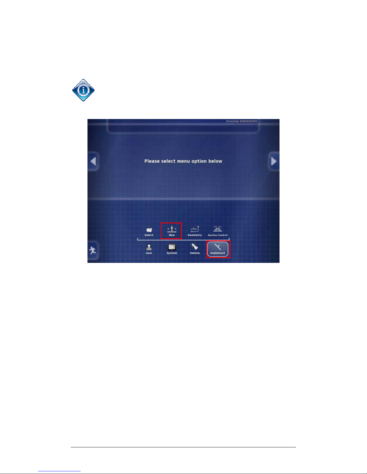
2.1 Setting up a New Implement
Follow the steps below to create a new implement.
Implement information files can be imported from a USB.
Refer to the X30 Guidance and Auto Steering manual.
1 Select Implement and Select New.
Page 23
Chapter 2 - Implement Setup 2.1 Setting up a New Implement
X30 Spreader Controller
2-3
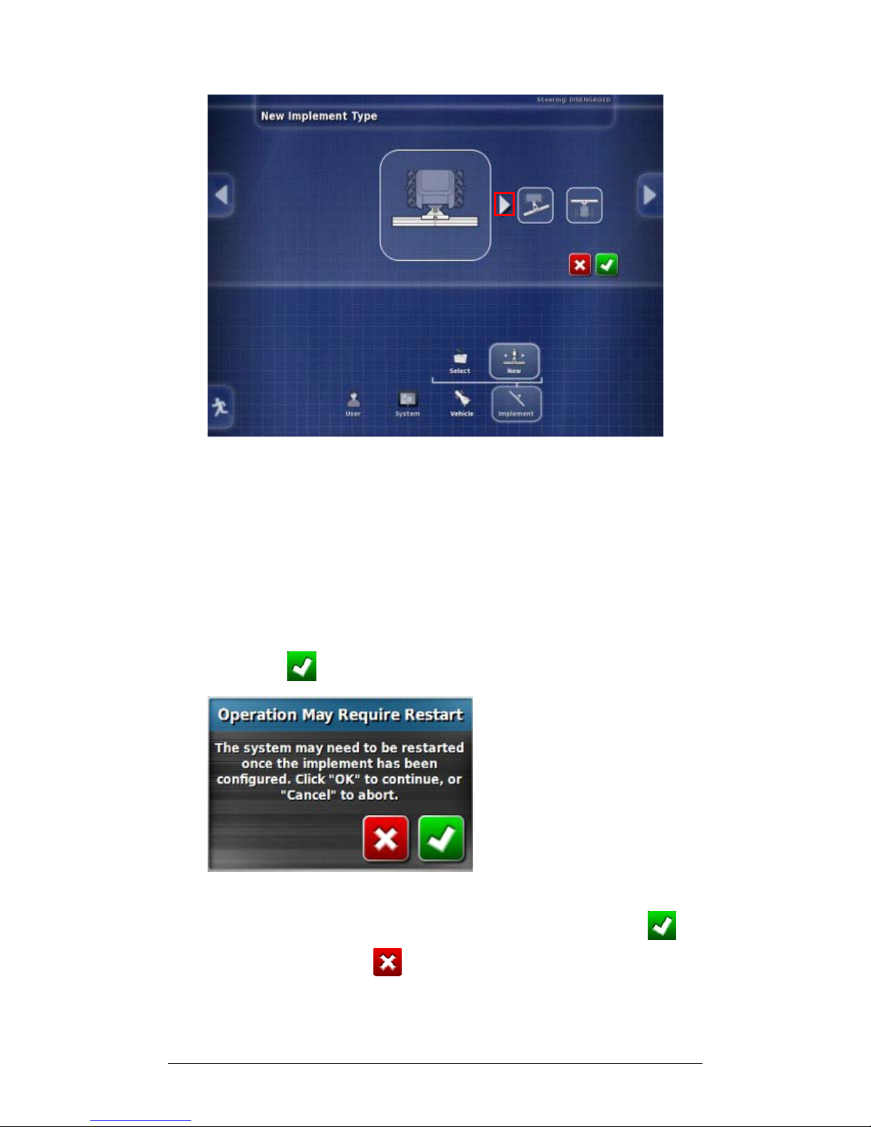
You may choose between:
Rigid
Front Mount
Pivoted (Tow behind)
Double Pivoted (Tow between).
2. Use the side arrows to choose an Implement Type and
Confirm .
3. The system will warn you that it may need to restart after
you have finished setting up the implement. Select to
continue (or select to cancel the action).
Page 24
Chapter 2 - Implement Setup 2.1 Setting up a New Implement
X30 Spreader Controller
2-4
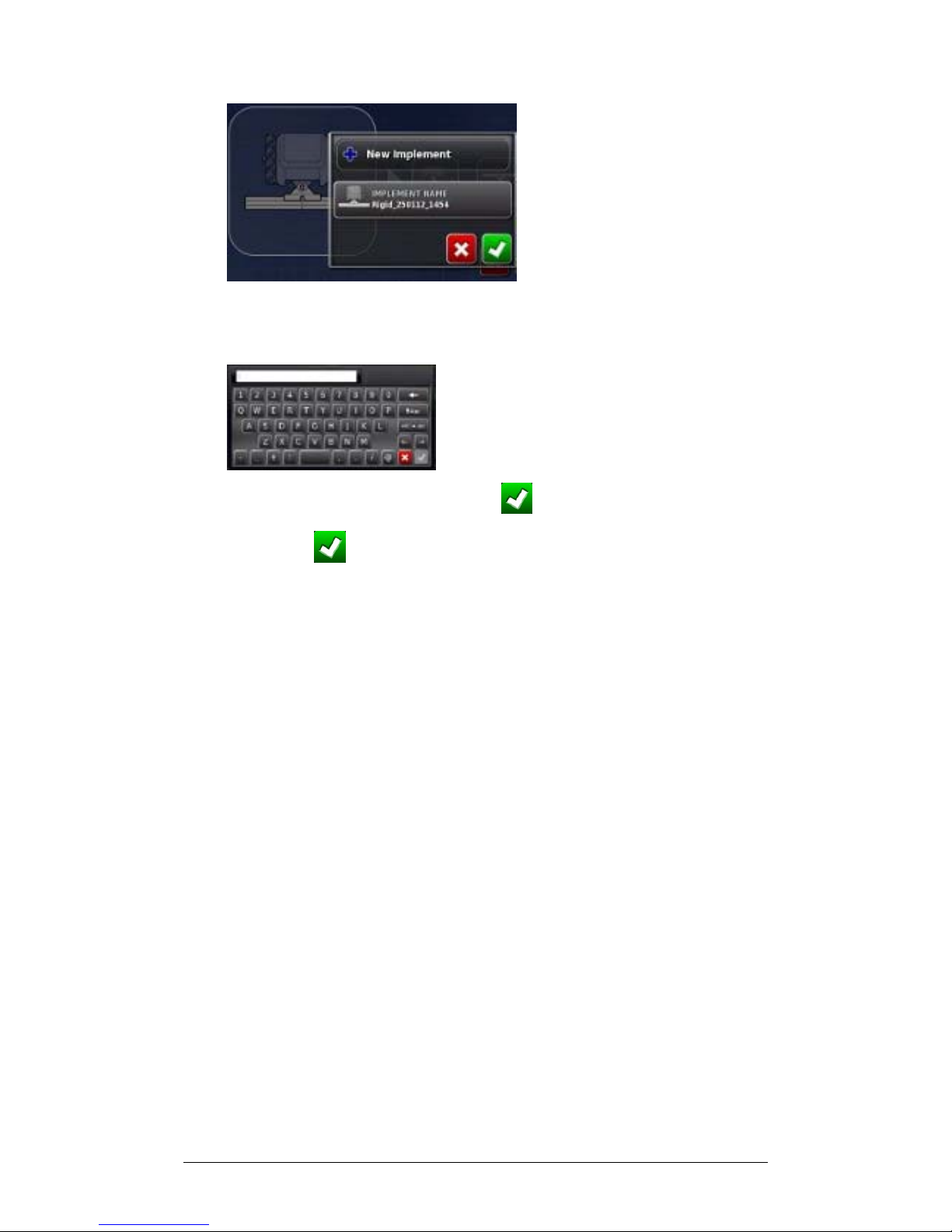
4. Select Implement Name if you wish to name your
implement.
5. Enter the name and Confirm .
6. Confirm the new implement details to continue.
Page 25

Chapter 2 - Implement Setup 2.2 Connecting to ECUs
X30 Spreader Controller
2-5
2.2 Connecting to ECUs
ECUs should be connected to the CAN2 connector on the
console’s termination harness. Start with all ECUs
disconnected from the CAN line and confirm that the harness
is connected to the console. Only one termination is
necessary, placed at the ECU farthest from the console.
Follow the steps below and, when prompted, connect the first
ECU to the CAN line. Only one ECU can be detected at a
time. Once each ECU is detected, connect the next ECU
when prompted.
The blue status indicator on the ASC-10 will flash three times
slowly, then three times quickly to indicate normal
operations.
Page 26
Chapter 2 - Implement Setup 2.3 Setting up the ECU
X30 Spreader Controller
2-6
2.3 Setting up the ECU
This will involve configuring ECU type, control function and
bin. The number of ECUs depends on the number of bins,
belts and spinners in your setup.
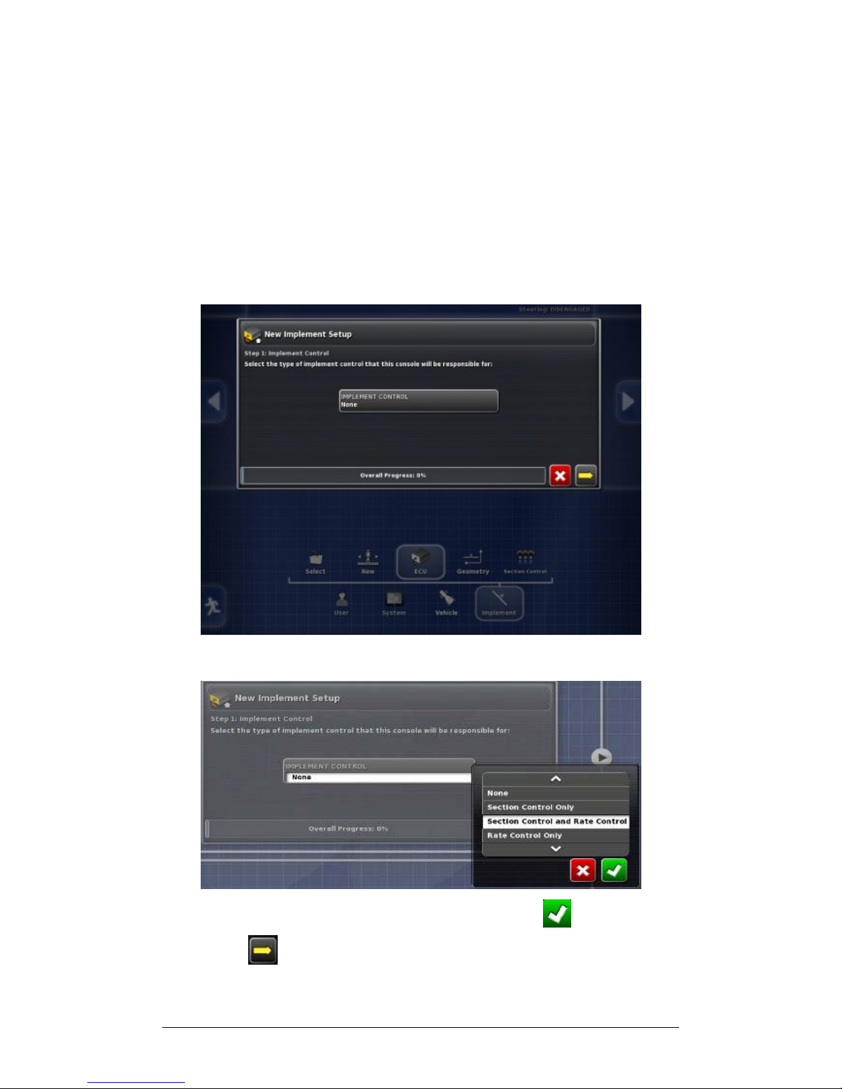
Setup for the ECU will begin automatically as part of
creating a new implement.
1. Select Implement Control.
2. Choose the control required and Confirm and select
Next .
Page 27
Chapter 2 - Implement Setup 2.3 Setting up the ECU
X30 Spreader Controller
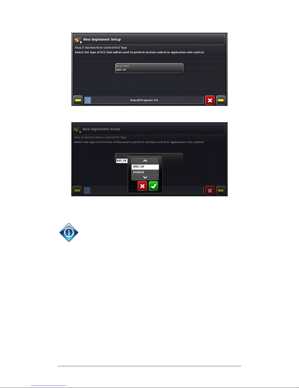
2-7
3. Select ECU Type.
4. Choose the type of ECU required, Confirm and select
Next.
Note that the Spreader Controller interface described in
Chapters 3 and 4 of this manual is only used to control
spreaders equipped with the Topcon ASC-10 ECUs.
If ISOBUS ECU is chosen, functionality will depend on
the ISOBUS unit connected. The ISOBUS ECU can be
operated through the Virtual Terminal feature of the X30
software. Please refer to the ISOBUS ECU documentation.
Minor variations in the following ECU setup options may
appear.
Page 28

Chapter 2 - Implement Setup 2.3 Setting up the ECU
X30 Spreader Controller
2-8
5. Select Implement Function.
6. Choose Spreader, Confirm and select Next.
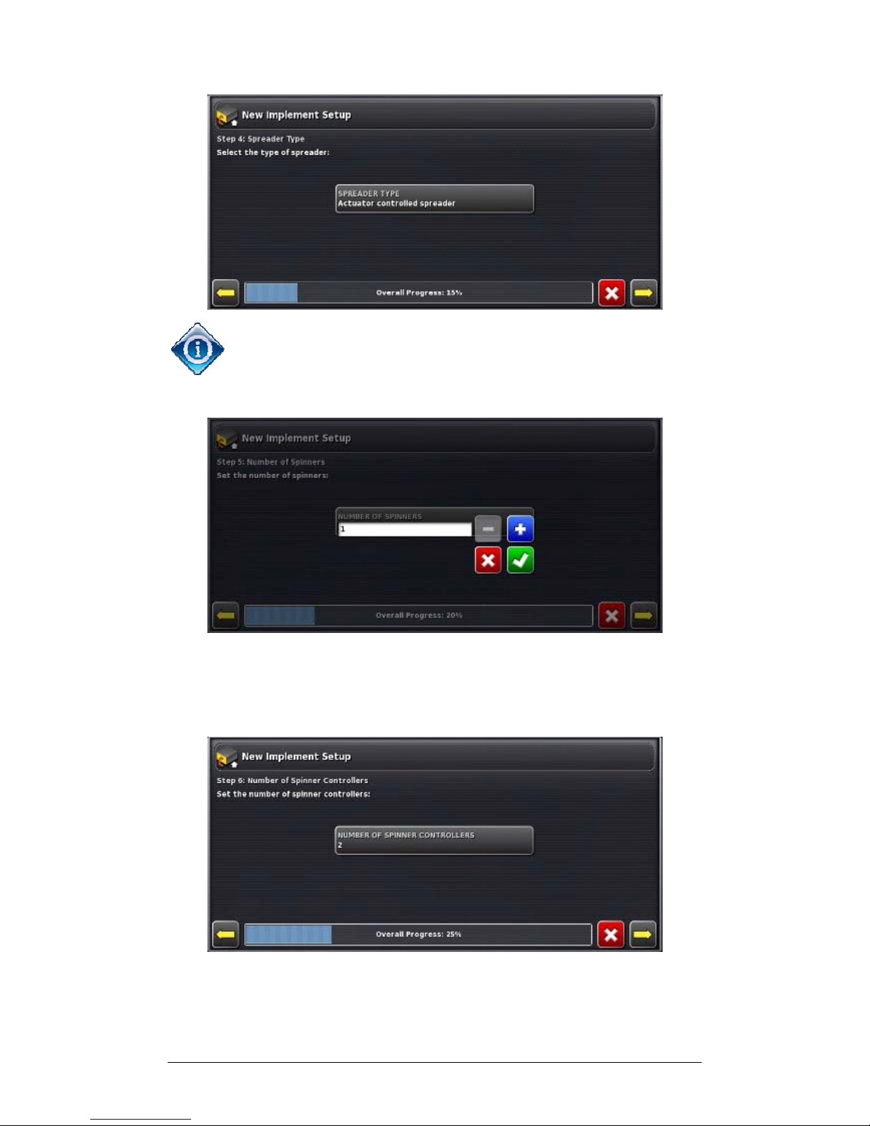
7. Select the type of Spreader, Confirm and select Next.
Page 29
Chapter 2 - Implement Setup 2.3 Setting up the ECU
X30 Spreader Controller
2-9
The choice of Actuator controlled or Belt Driven spreader
will affect the options offered and the number of steps
shown on the screens. Follow the screen prompts.
8. Select Number of Spinners. Use plus or minus to choose
the number of spinners, Confirm and select Next. If only
one spinner is set, go to Step 10.
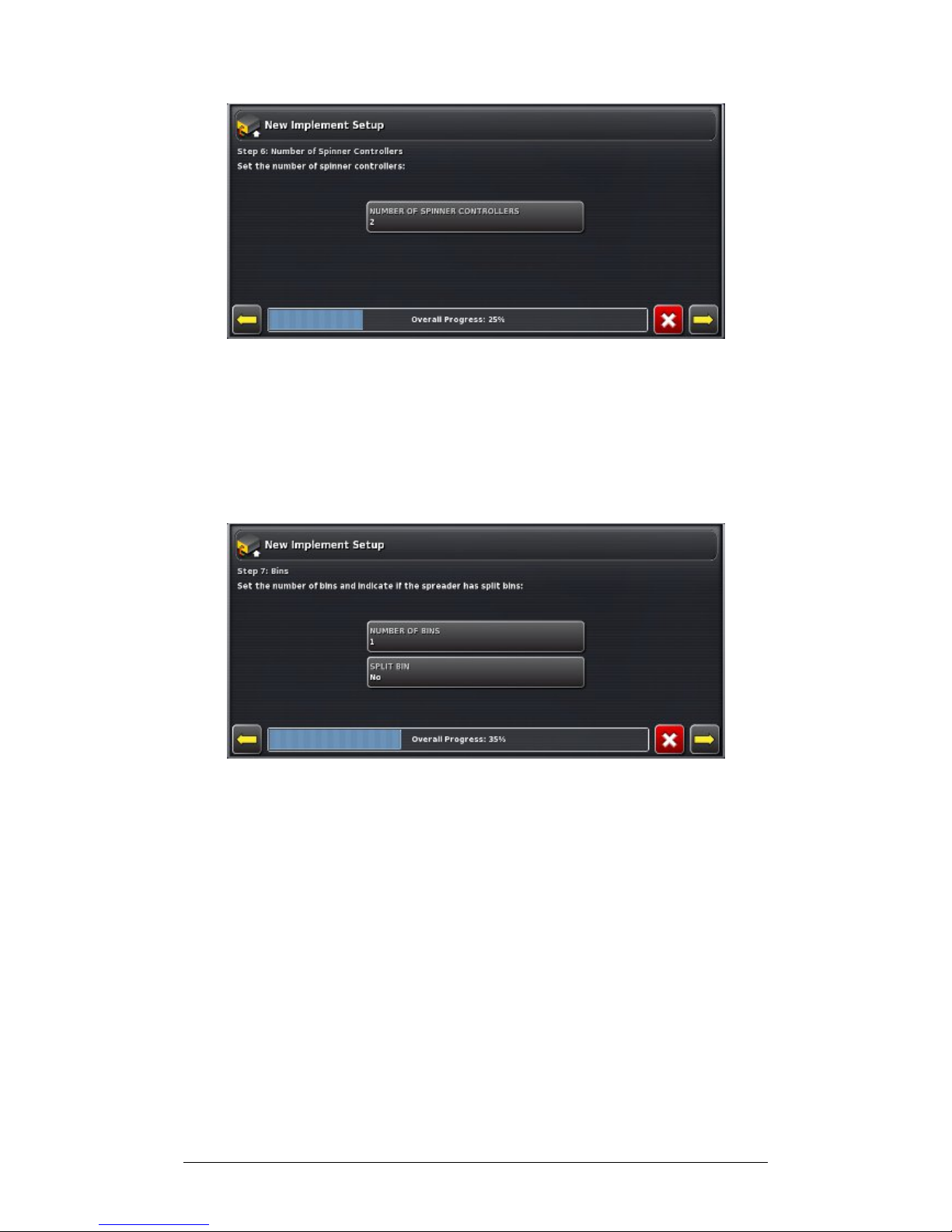
9. If more than one spinner has been set the following
screen will display.
Page 30
Chapter 2 - Implement Setup 2.3 Setting up the ECU
X30 Spreader Controller
2-10
9a. Select Number of Spinner Controllers. Use plus or minus
to enter the number of spinner controllers, Confirm and
select Next.
9b. Select Number of Spinner Monitors, and use plus or
minus to enter the number, Confirm and select Next.
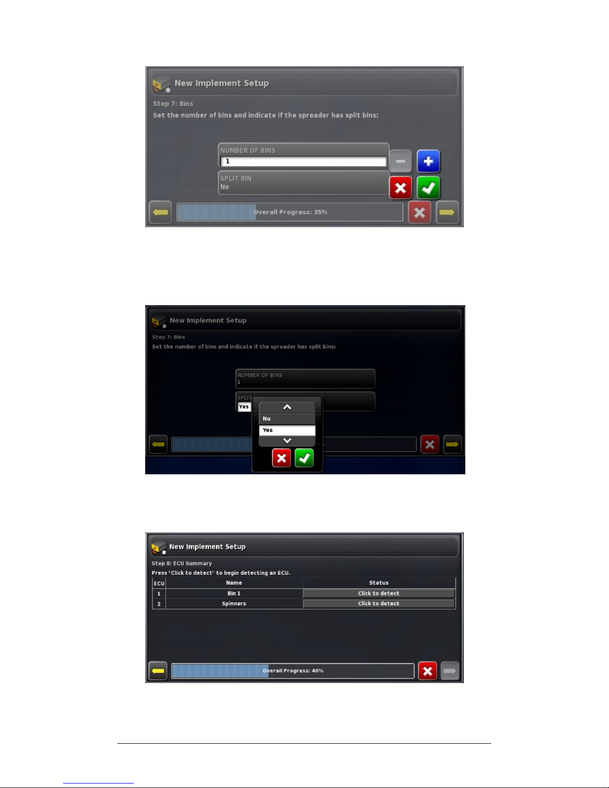
10. Select Number of Bins.
Page 31
Chapter 2 - Implement Setup 2.3 Setting up the ECU
X30 Spreader Controller
2-11
11. Use plus or minus to enter the number of bins and
Confirm.
11a. For belt driven spreaders, select Split Belt, if required.
11b. Choose Yes or No and Confirm.
12. Select Next.
13. Connect an ECU.
Page 32
Chapter 2 - Implement Setup 2.3 Setting up the ECU
X30 Spreader Controller
2-12
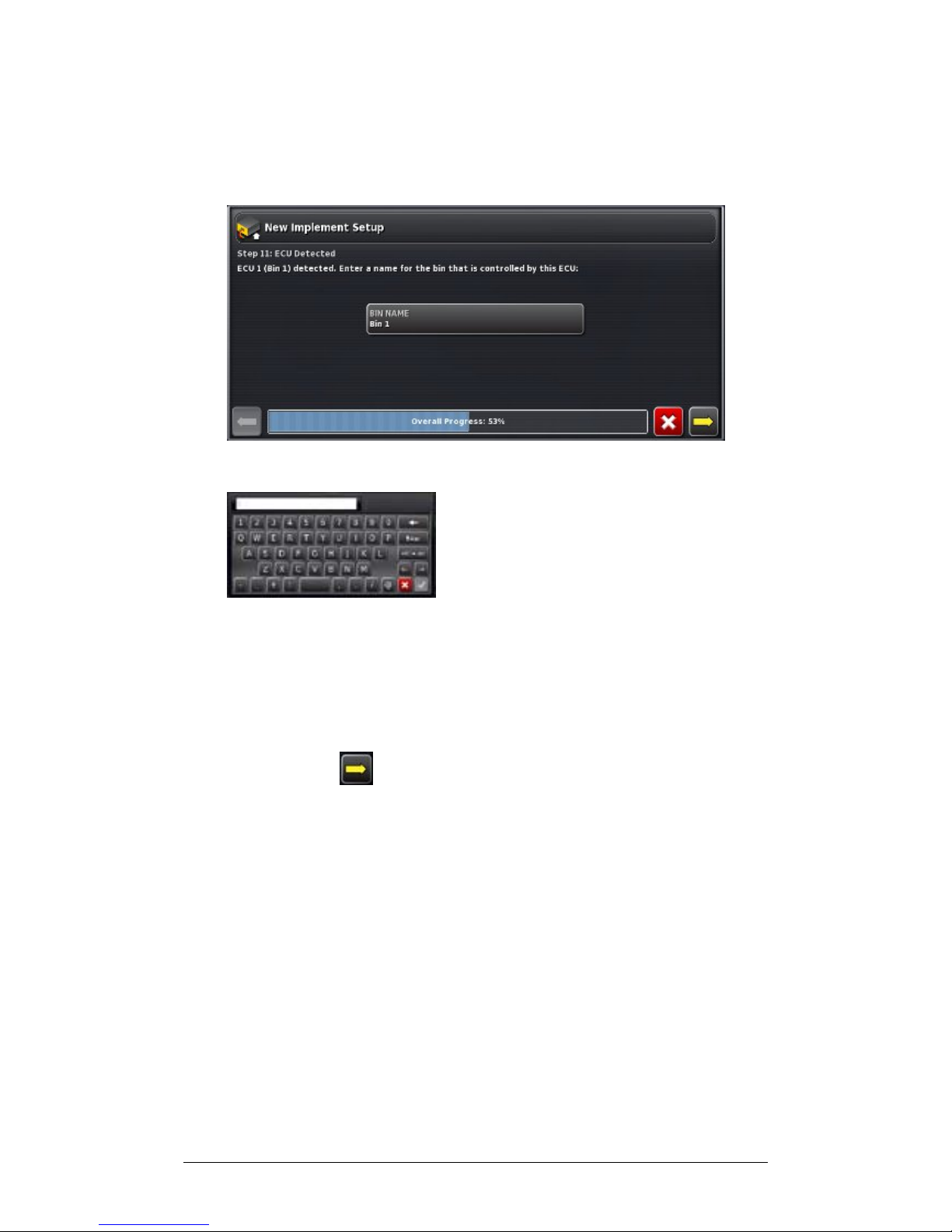
14. Select Click to Detect to begin detecting ECU. Each
ECU will need to be connected and then detected one at
a time.
15. For bins, select Bin Name to change the default name.
16. Enter a name for the Bin and Confirm.
17. Repeat steps 13-16 until all ECUs are detected for bins
and spinners.
18. Check that all connected ECUs are now connected and
select Next .
Page 33
Chapter 2 - Implement Setup 2.4 Setting up Implement Geometry
X30 Spreader Controller
2-13
2.4 Setting up Implement Geometry
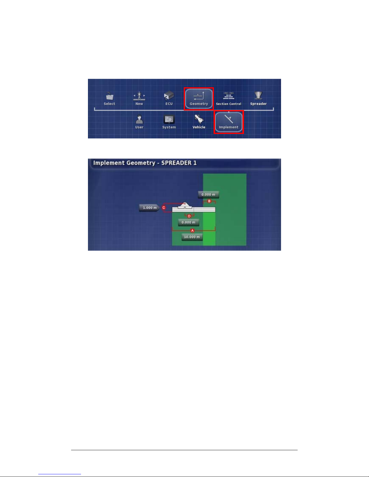
Follow these steps to configure the implement geometry.
1. From the menu, select Geometry.
2. Select a measurement. The type of measurement will
appear in the Title Bar.
Swath width measures the width of the implement
(that is, the width of the area that is treated during
one pass of the implement).
Overlap measures the width of the overlap between
two adjacent rows.
Implement offset measures the distance between the
hitch point and the application end of the implement.
Inline Offset measures the off-centre offset of the
implement relative to the hitch point. Enter a
positive number if the implement is shifted to the
right and a negative number if it is shifted to the left.
Page 34
Chapter 2 - Implement Setup 2.4 Setting up Implement Geometry
X30 Spreader Controller
2-14
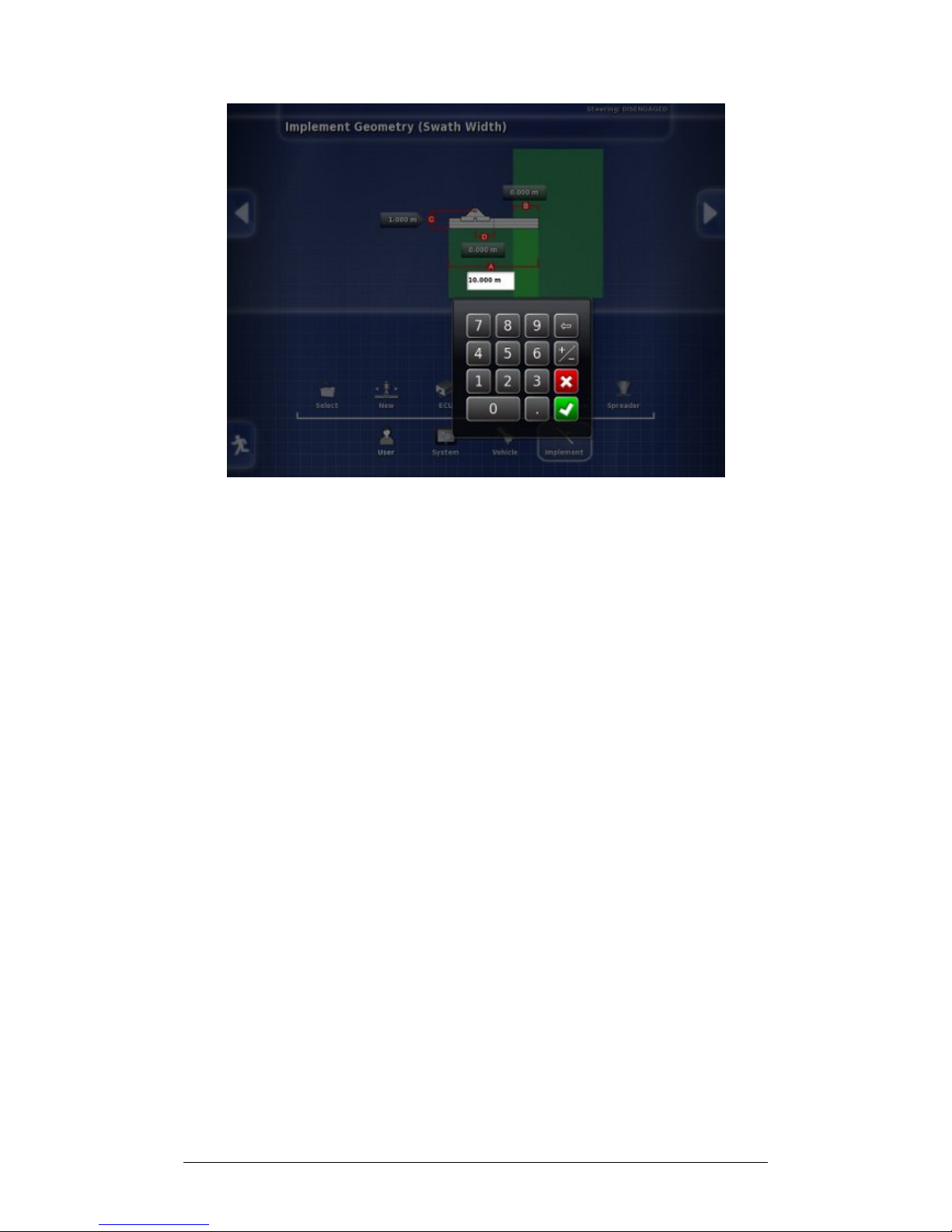
3. Enter the measurement and Confirm.
4. Repeat for each measurement.
Page 35
Chapter 2 - Implement Setup 2.5 Setting up Section Control
X30 Spreader Controller
2-15
2.5 Setting up Section Control
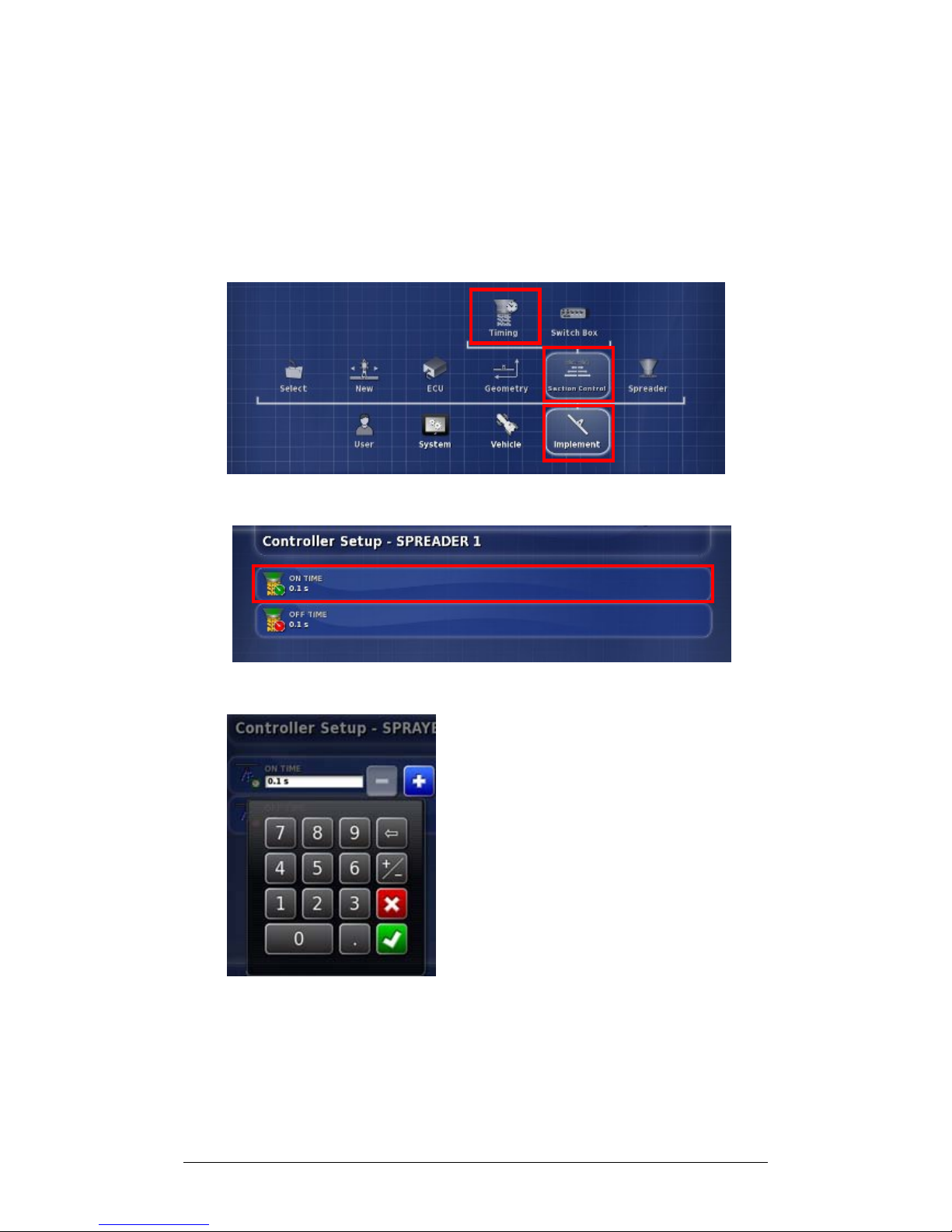
Follow these steps to set up Section Control for the
implement.
2.5.1 Setting On Time and Off Time
1. Select Section Control and select Timing.
2. Select On Time.
3. Use plus or minus or enter how many seconds delay
there is between switching a section on and the
application of product. Confirm.
Page 36

Chapter 2 - Implement Setup 2.5 Setting up Section Control
X30 Spreader Controller
2-16
4. Repeat for Off Time and Confirm. This will set how
many seconds delay there is between switching a section
off and stopping product flow.
Page 37
Chapter 2 - Implement Setup 2.5 Setting up Section Control
X30 Spreader Controller
2-17
2.5.2 Setting up the Switch Box
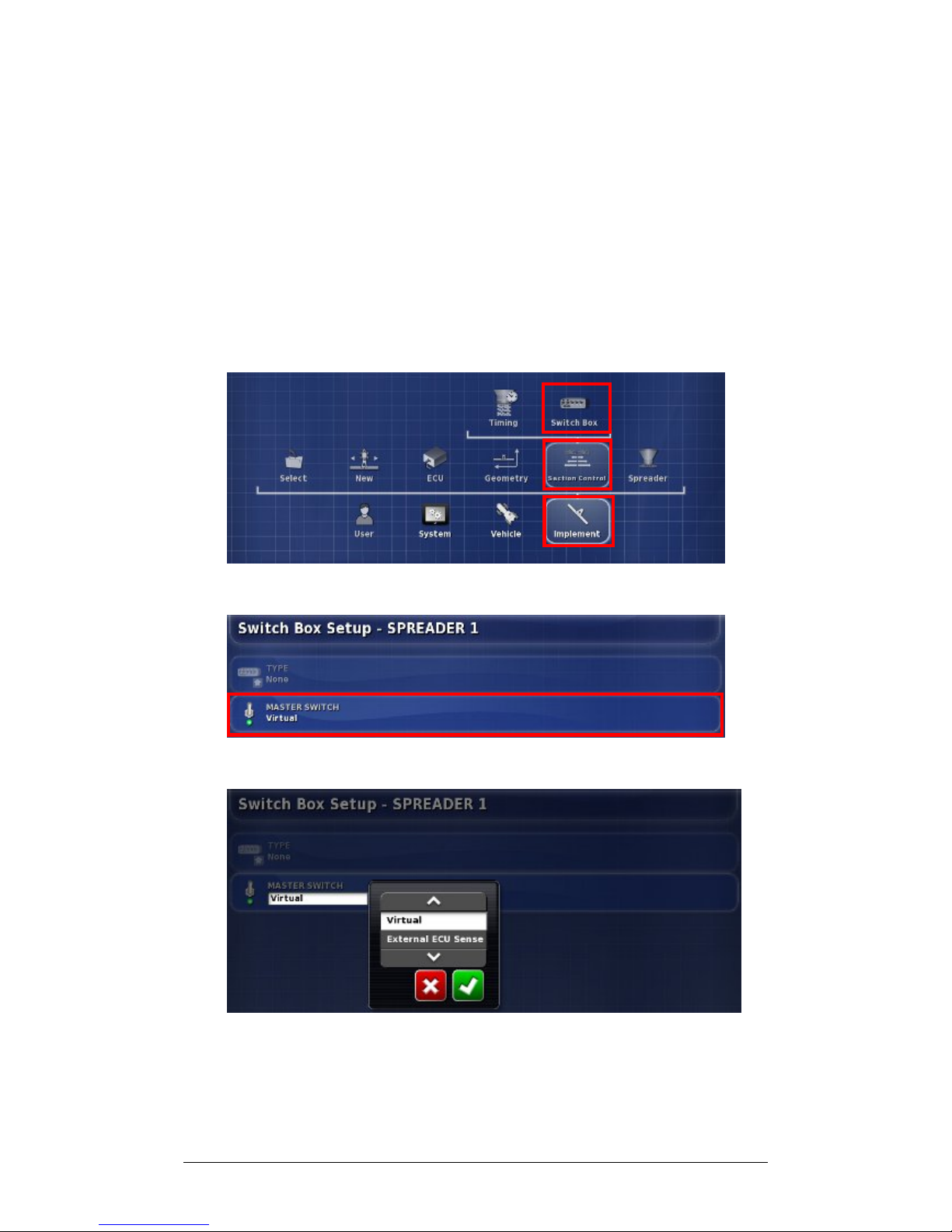
The Master Switch can be either Virtual (on the X30 screen)
or External (a physical Master Switch connected to the ASC10 ECU). Type of switch box cannot be selected with
spreaders as the spinners’ on/off action controls the two
sections.
Follow these steps to configure the Switch Box.
1. Select Section Control and select Switch Box.
2. Select Master Switch.
3. Select Virtual or External ECU Sense and Confirm.
Choosing Virtual Master Switch will enable the Spreader
Master Switch on the console.
Page 38
Chapter 2 - Implement Setup 2.6 Enabling Auto Section Control
X30 Spreader Controller
2-18
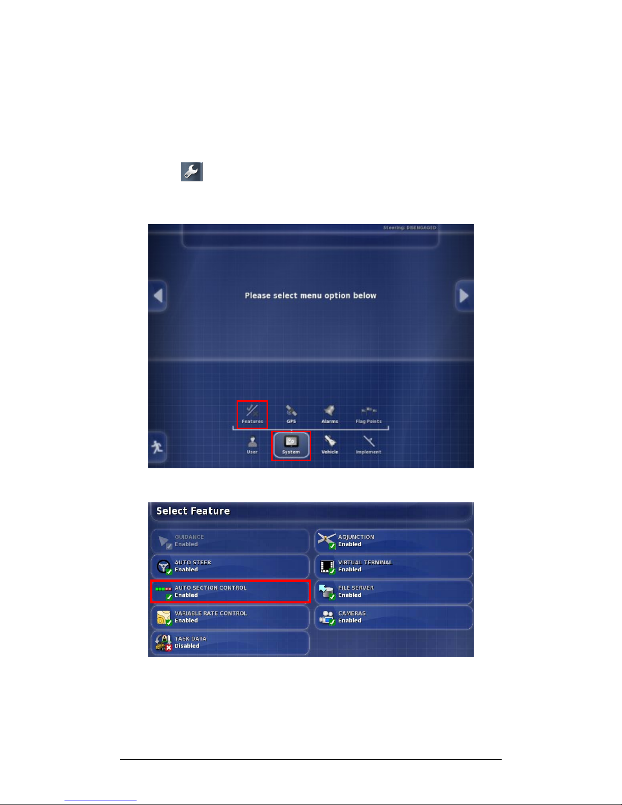
2.6 Enabling Auto Section Control
Auto Section Control needs to be enabled to use the feature
during operations. If this has not been done earlier, return to
the X30 Main Setup screen from operations screens, by
selecting .
1. Select System on the Main Setup Menu.
2. Select Features to view feature options.
3. Select Auto Section Control.
Page 39
Chapter 2 - Implement Setup 2.6 Enabling Auto Section Control
X30 Spreader Controller
2-19
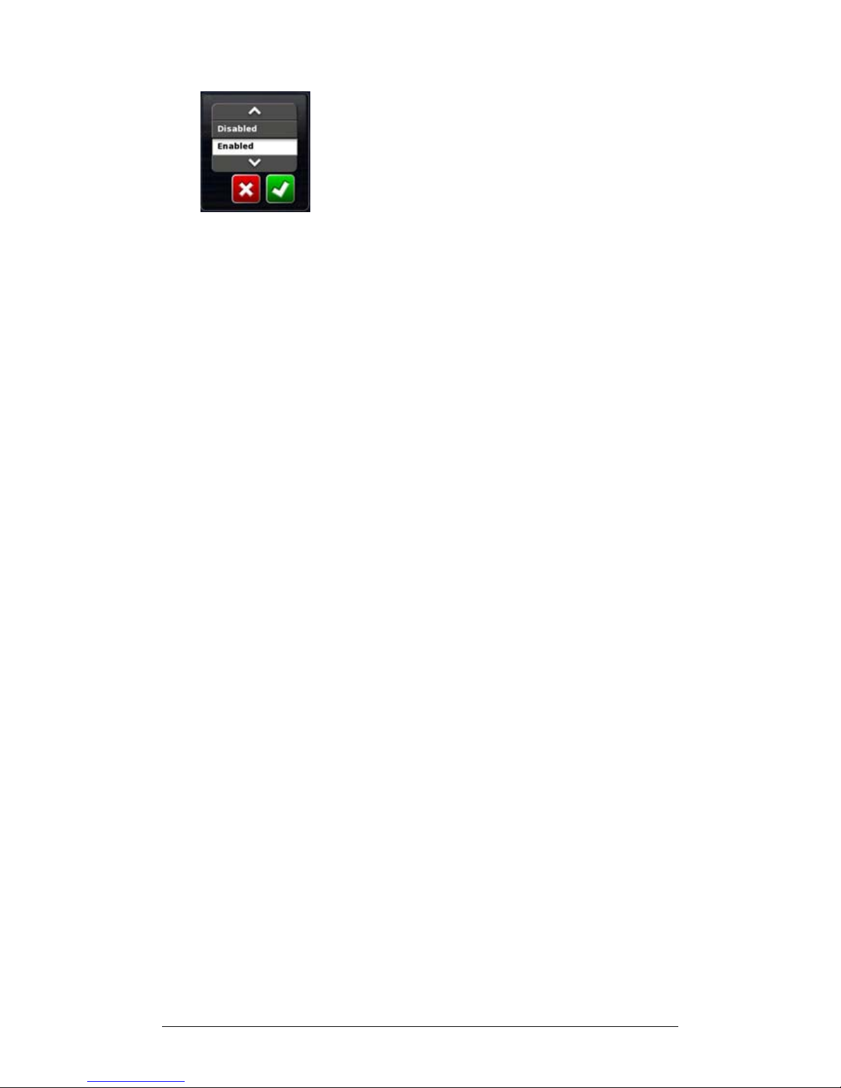
4. Choose Enabled and Confirm (or choose Disabled and
Confirm to turn the feature off).
Page 40

X30 Spreader Controller
3-1
Chapter 3 - Spreader Controller Setup
The X30 Spreader Controller allows the operator to manage
the amount of product being applied. Through the controller
bins, spinners and rates can be set and then adjusted as
needed during work in a field. To do this the system needs
information about the type of spreader that is being used and
how the operator wants it to work.
3.1 Setting up Spreader Controller
3.2 Setting up Actuator
3.3 Setting up Control Valve (Proportional)
3.4 Setting up Control Valve (Belt Regulator)
3.5 Setting up Spinners
3.6 Setting up Spinner Control Valves
3.7 Setting up Wheel Sensor
3.6 Setting Alarms
Page 41
Chapter 3 - Spreader Controller Setup 3.1 Setting up Spreader Controller
X30 Spreader Controller
3-2
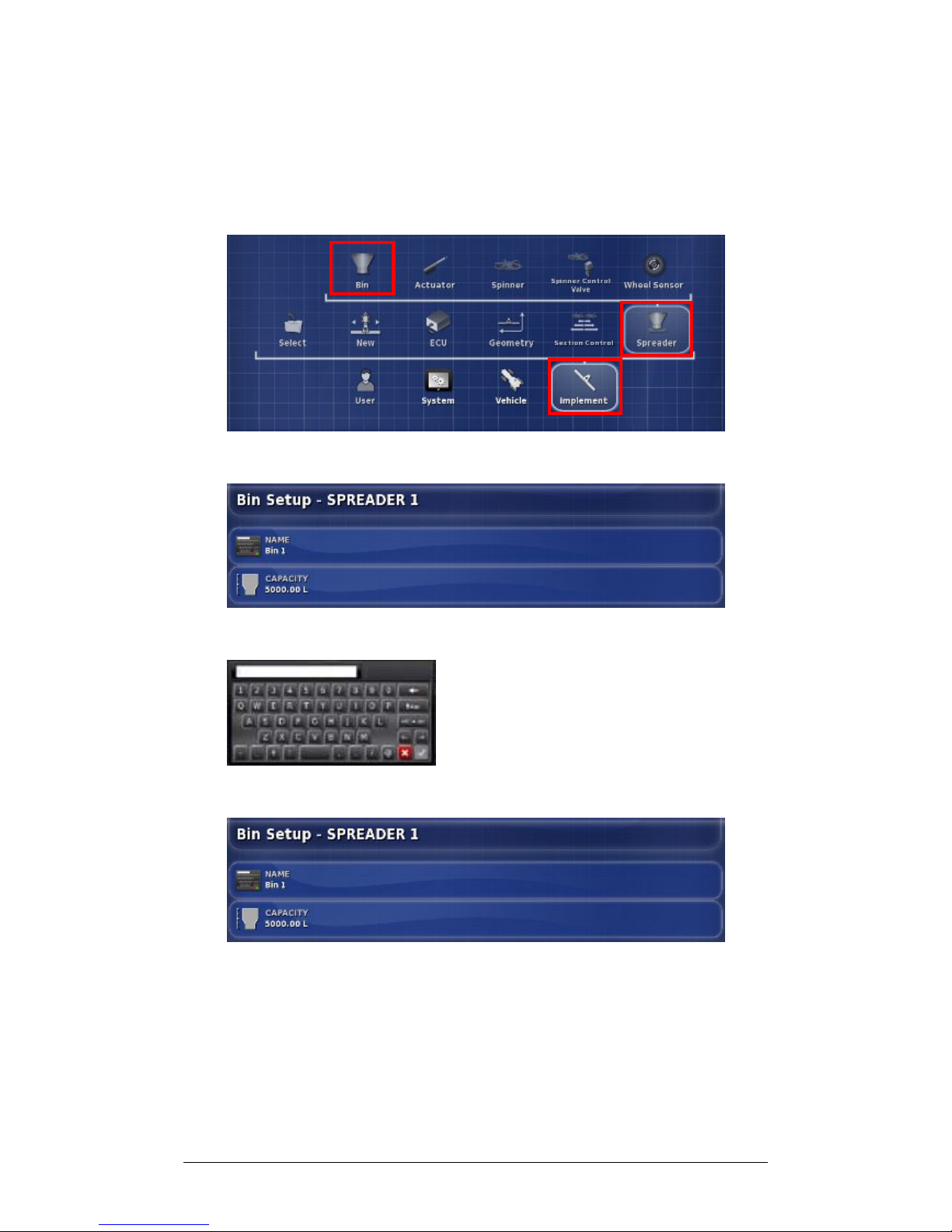
3.1 Setting up Spreader Controller
Follow the steps to set up Spreader Controller bin
requirements.
1. Select Spreader and select Bin.
2. Select Name.
3. Enter a name and Confirm.
4. Select Capacity.
Page 42
Chapter 3 - Spreader Controller Setup 3.1 Setting up Spreader Controller
X30 Spreader Controller
3-3
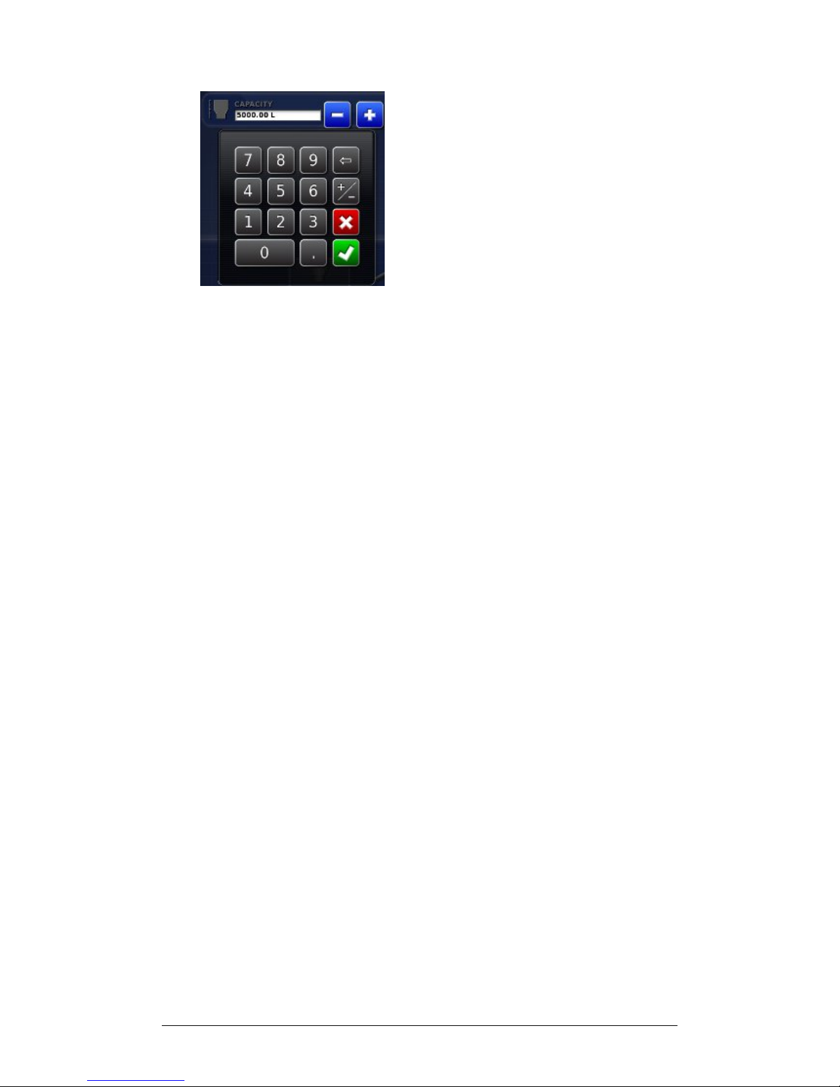
5. Enter the bin capacity and Confirm.
Page 43
Chapter 3 - Spreader Controller Setup 3.2 Setting up Actuator
X30 Spreader Controller
3-4
3.2 Setting up Actuator
The Actuator manages the flow and timing of the product. If
the implement uses a belt drive, go to Section 3.3 Setting up
Control Valve (Proportional) or Section 3.4 Setting Control
Valve (Regulator).
Always refer to the specific implement manual to
set appropriate flow controls for the implement.
Follow the steps to set up control for an actuator driven
implement.
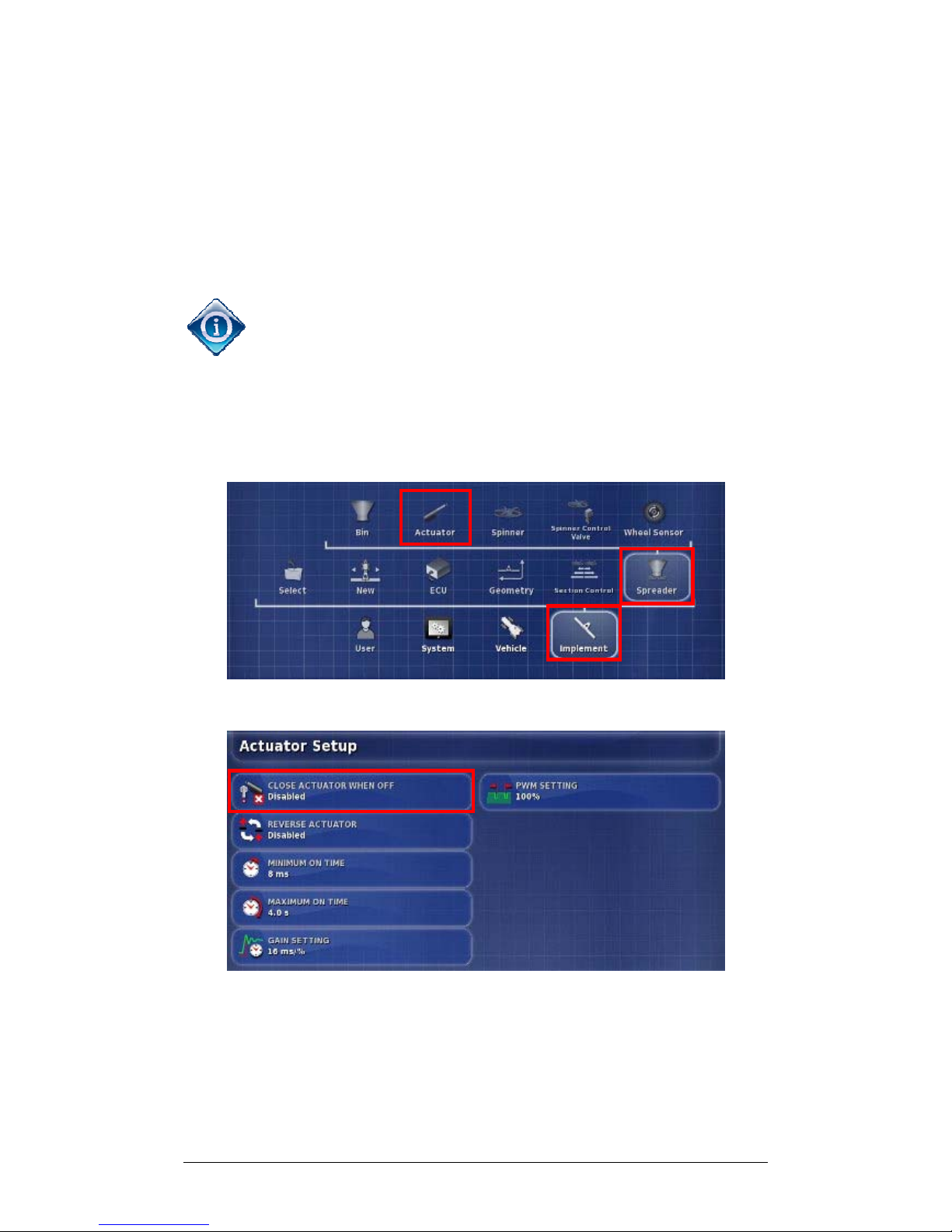
1. Select Actuator.
2. To fully close the actuator when the master switch is off,
select Close Actuator When Off.
Page 44
Chapter 3 - Spreader Controller Setup 3.2 Setting up Actuator
X30 Spreader Controller
3-5
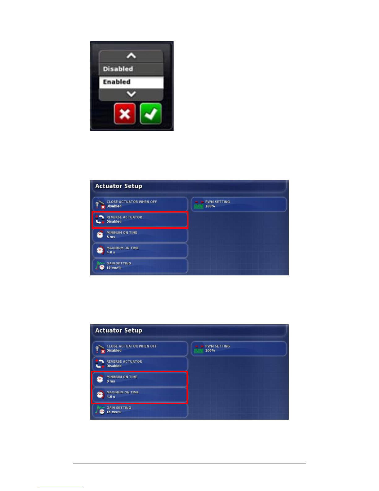
3. Select Enabled and Confirm.
4. In some cases the actuator may have been wired to work
in the opposite direction.
4a. To allow the actuator to work in reverse, select Reverse
Actuator.
4b. Choose Enabled and Confirm.
5. Select Minimum On Time. This sets the minimum time
to apply power to start the actuator moving.
Page 45
Chapter 3 - Spreader Controller Setup 3.2 Setting up Actuator
X30 Spreader Controller
3-6
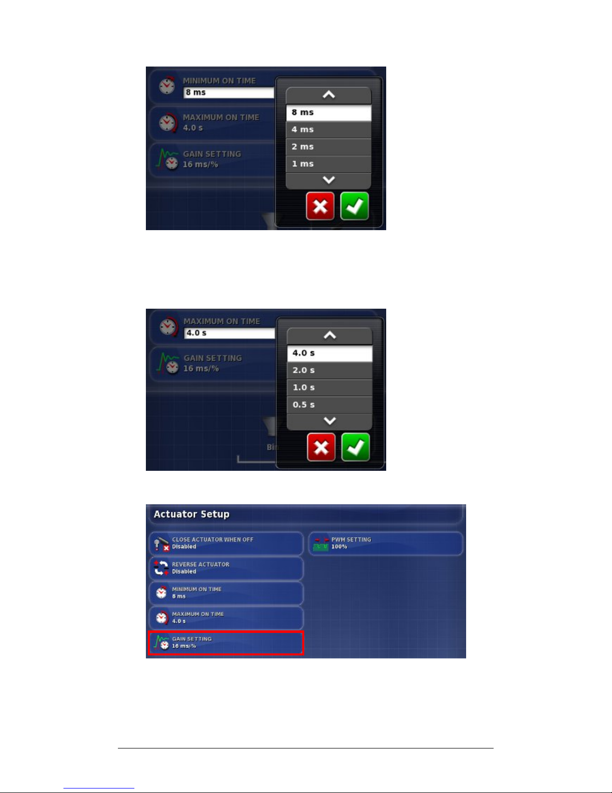
6. Choose response time and Confirm.
7. Select Maximum On Time. This sets the maximum time
to apply power to move the actuator to position.
8. Choose maximum time and Confirm.
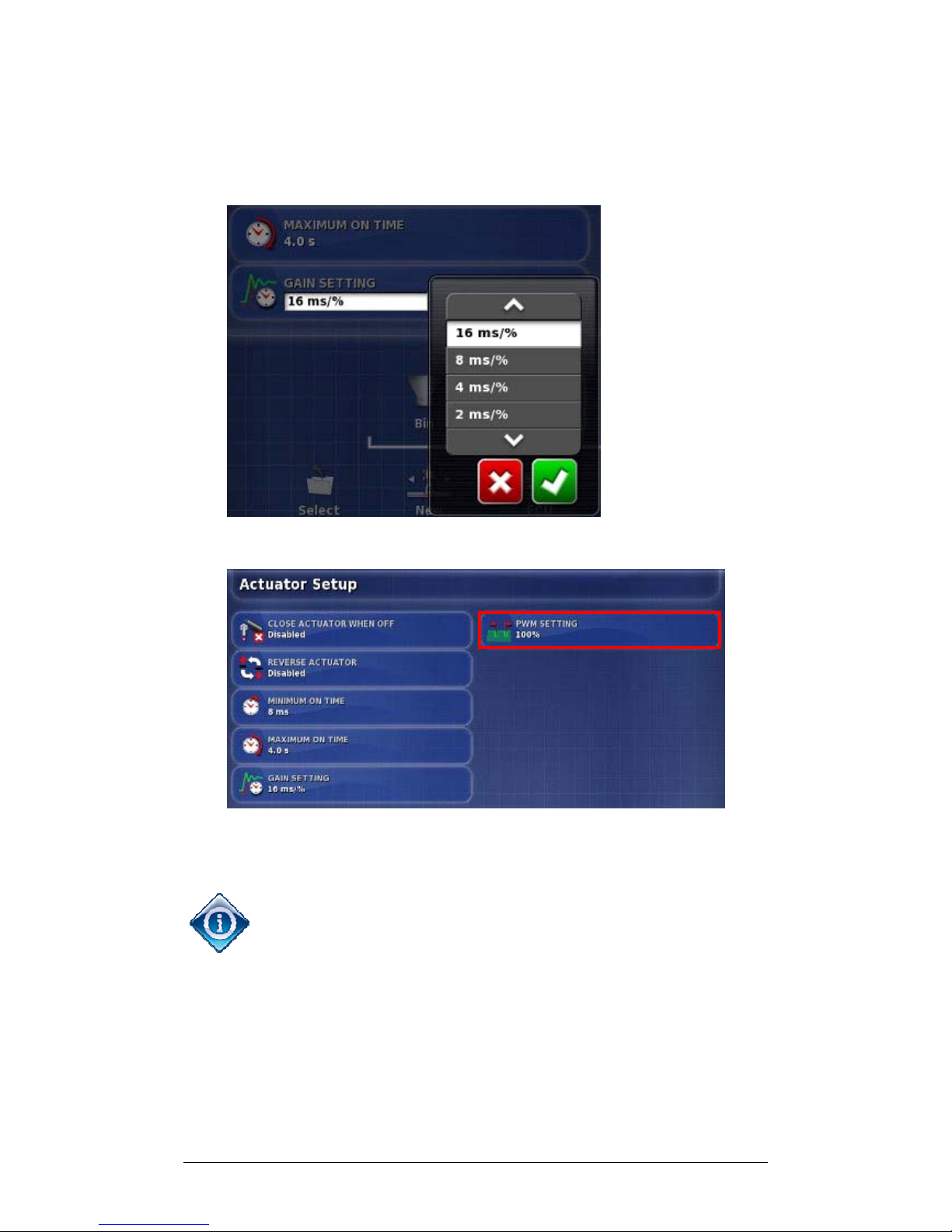
9. To change the gain setting select Gain Setting. This will
set how quickly the controller will try to achieve the
required rate. If set too high, the spreader may pass the
Page 46
Chapter 3 - Spreader Controller Setup 3.2 Setting up Actuator
X30 Spreader Controller
3-7
target rate and take time to adjust, searching for the right
level. Find the best gain percentage for the equipment
being used.
10. Choose setting and Confirm.
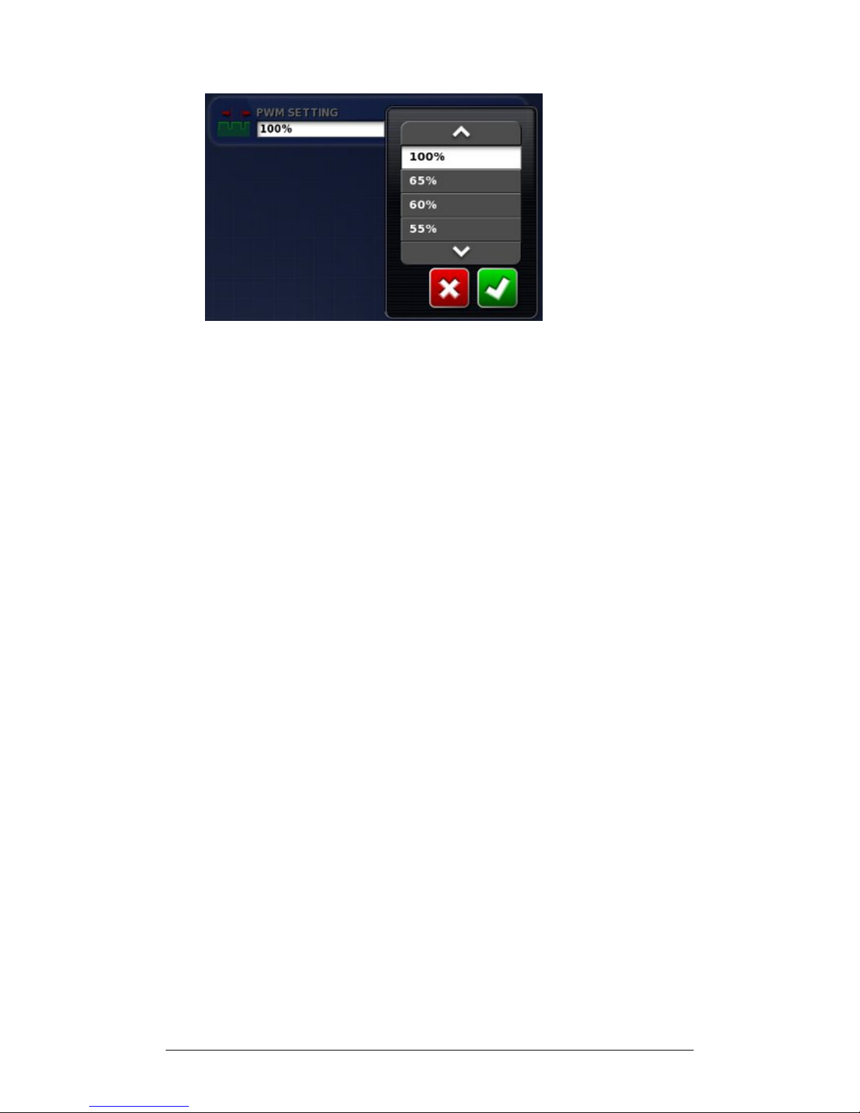
11. To change the percentage of time for the Pulse Width
Modulation (PWM) to be active, select PWM Setting.
PWM stands for Pulse Width Modulation. Control of a
motor or valve is achieved by varying the amount of time
power is switched on/off. This happens at a very fast rate.
PWM is used to reduce the overall applied voltage to the
actuator. Use with caution as this will reduce the torque
that the actuator is able to apply.
Page 47
Chapter 3 - Spreader Controller Setup 3.2 Setting up Actuator
X30 Spreader Controller
3-8
12. Choose the desired percentage and Confirm. Go to
Section 3.5 Setting up Spinners.
Page 48
Chapter 3 - Spreader Controller Setup 3.3 Setting up Control Valve (Proportional)
X30 Spreader Controller
3-9
3.3 Setting up Control Valve (Proportional)
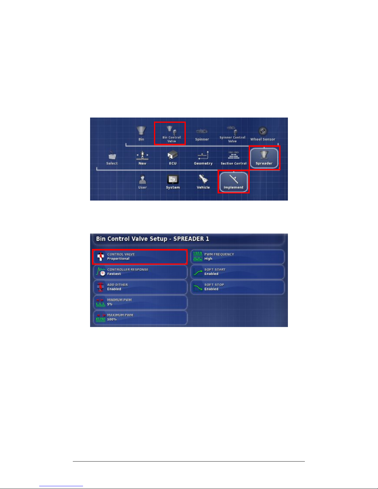
The Bin Control Valve manages the flow and timing of the
product. If the implement uses an Actuator, refer to Section
3.2 Setting up Actuator. These settings aim to ensure that the
spreader is operating at an efficient flow rate.
1. Select Implement, Spreader, and select Bin Control
Valve.
1a. Check that the selected control valve is Proportional
(default).
1b. If not, select Control Valve.
Page 49
Chapter 3 - Spreader Controller Setup 3.3 Setting up Control Valve (Proportional)
X30 Spreader Controller
3-10
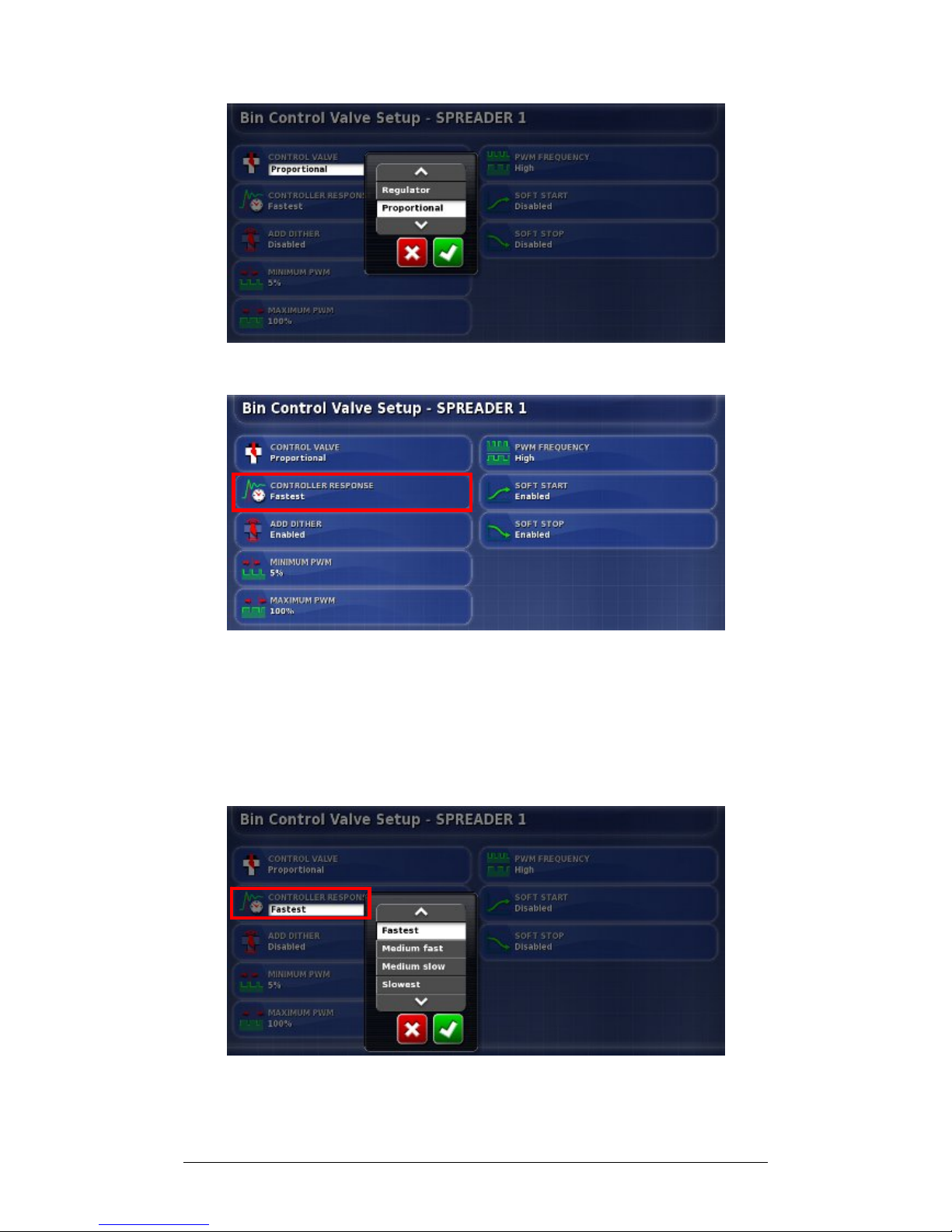
1c. Choose Proportional and Confirm.
2. Select Controller Response. This will set how quickly the
spreader will respond to adjustment. If set too high, the
spreader may pass the target rate and take time to adjust,
searching for the right level. Find the best response rate
for the equipment being used.
3. Choose the desired speed and Confirm.
Page 50
Chapter 3 - Spreader Controller Setup 3.3 Setting up Control Valve (Proportional)
X30 Spreader Controller
3-11
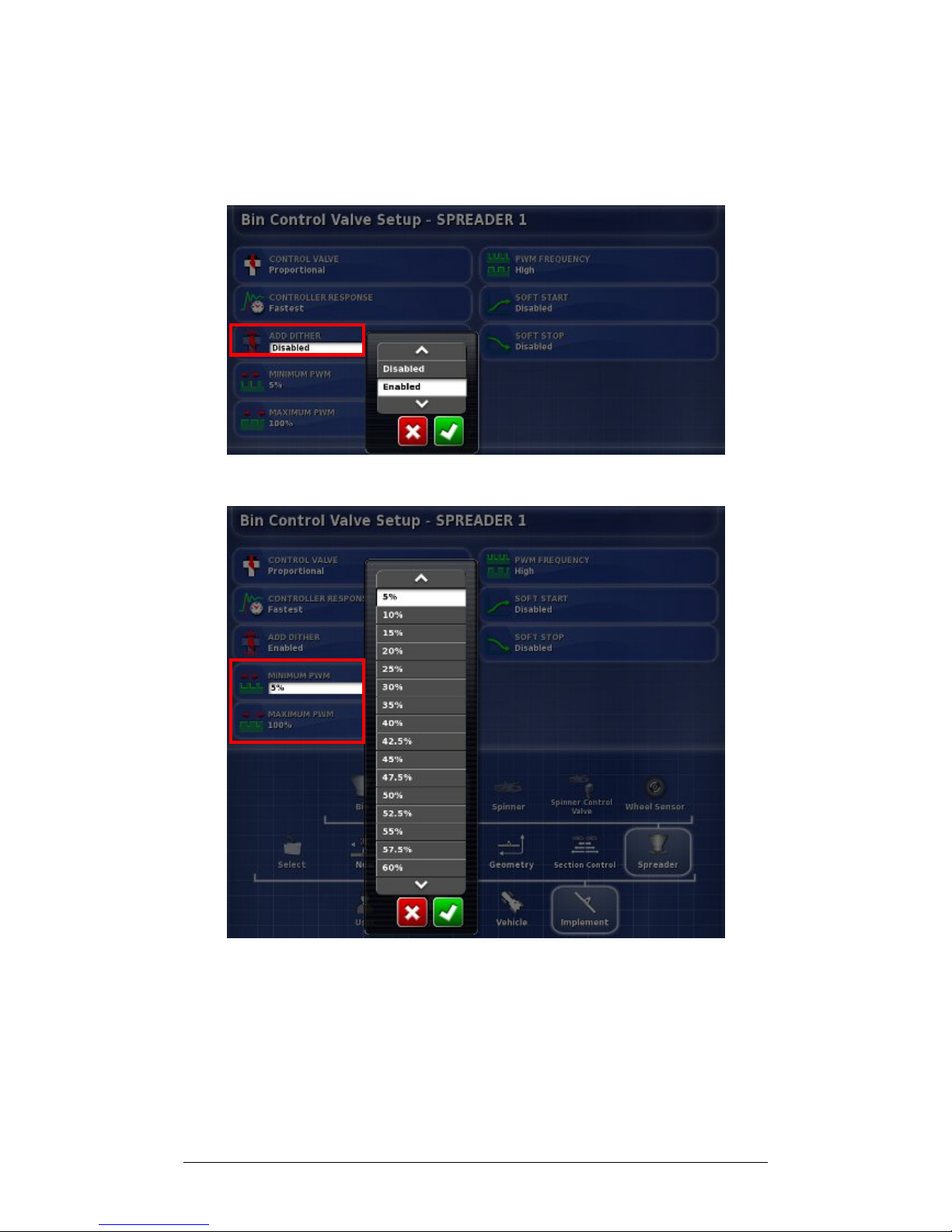
4. To enable dither, select Add Dither. Dither makes the
valve vibrate slightly to help prevent sticking. Do not use
this feature with Sauer Danfoss PWM Valves.
5. Choose Enabled and Confirm.
6. To change the minimum percentage of time for the Pulse
Width Modulation (PWM) to be active, select PWM
Setting. Minimum PWM is the minimum amount of
power required to allow a response. Anything under this
figure the valve will not respond.
Page 51
Chapter 3 - Spreader Controller Setup 3.3 Setting up Control Valve (Proportional)
X30 Spreader Controller
3-12
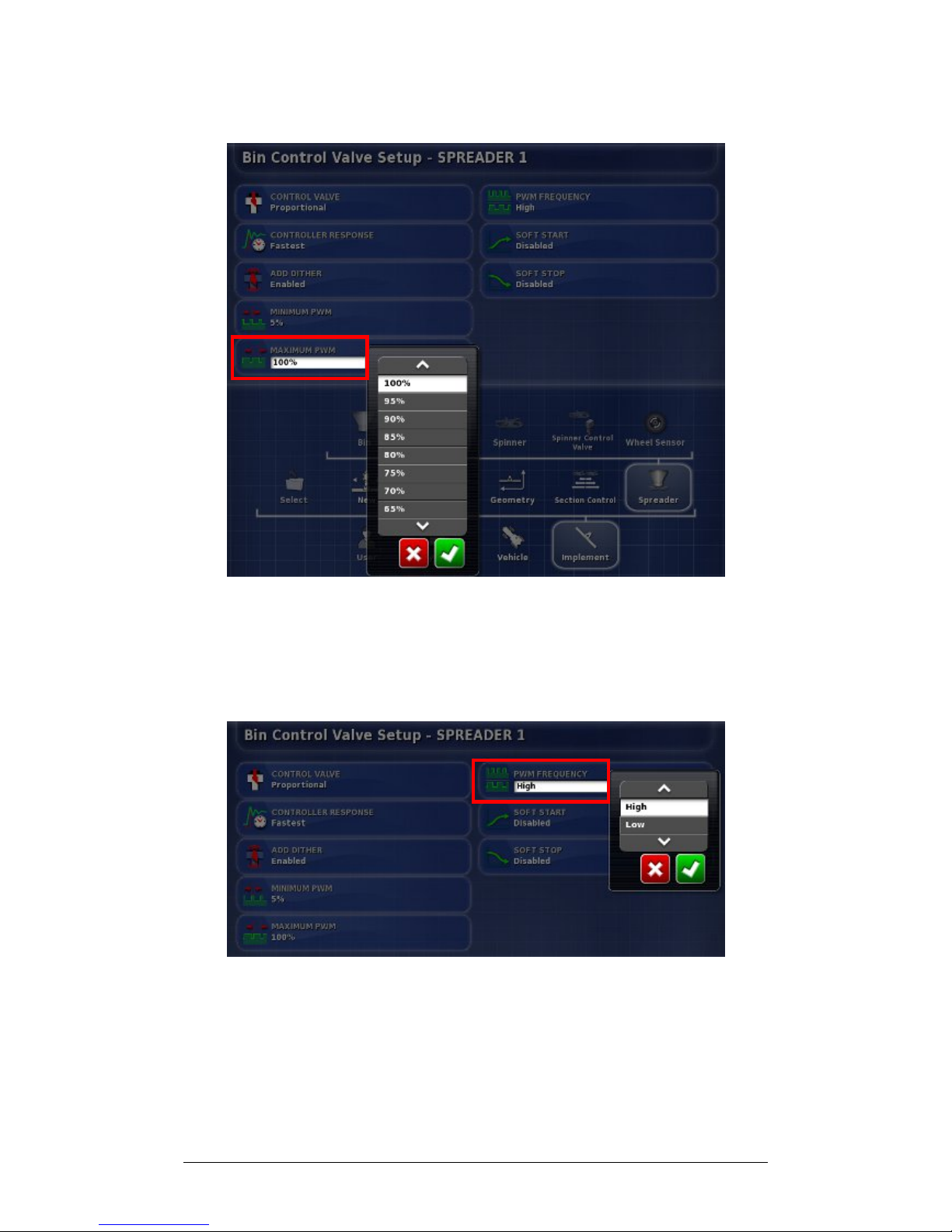
7. Choose percentage and Confirm.
8. Repeat for Maximum PWM. This is the maximum
amount of power that can be applied that will increase
the valve speed. Anything over this figure and the valve
speed will not increase.
9. Select PWM Frequency.
10. Choose frequency and Confirm.
Page 52
Chapter 3 - Spreader Controller Setup 3.3 Setting up Control Valve (Proportional)
X30 Spreader Controller
3-13
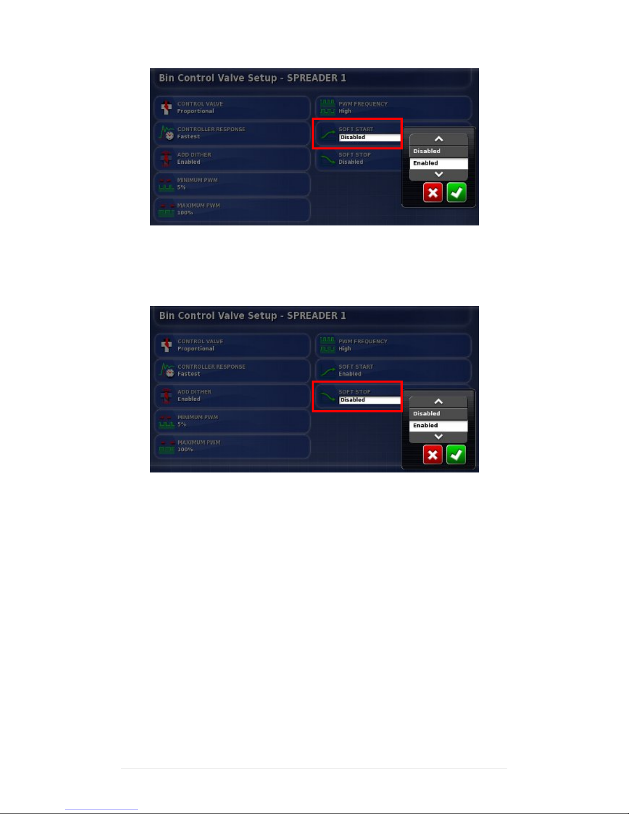
11. To allow gradual increase in the valve signal when the
valve is activated, select Soft Start.
12. Choose Enabled and Confirm.
13. To allow gradual decrease in the valve signal when the
valve is de-activated, select Soft Stop, choose Enabled
and Confirm.
Page 53
Chapter 3 - Spreader Controller Setup 3.4 Setting up Control Valve (Regulator)
X30 Spreader Controller
3-14
3.4 Setting up Control Valve (Regulator)
The Bin Control Valve manages the flow and timing of the
product. These settings aim to ensure that the spreader is
operating at an efficient flow rate. If the implement uses an
Actuator, refer to Section 3.2 Setting up Actuator.
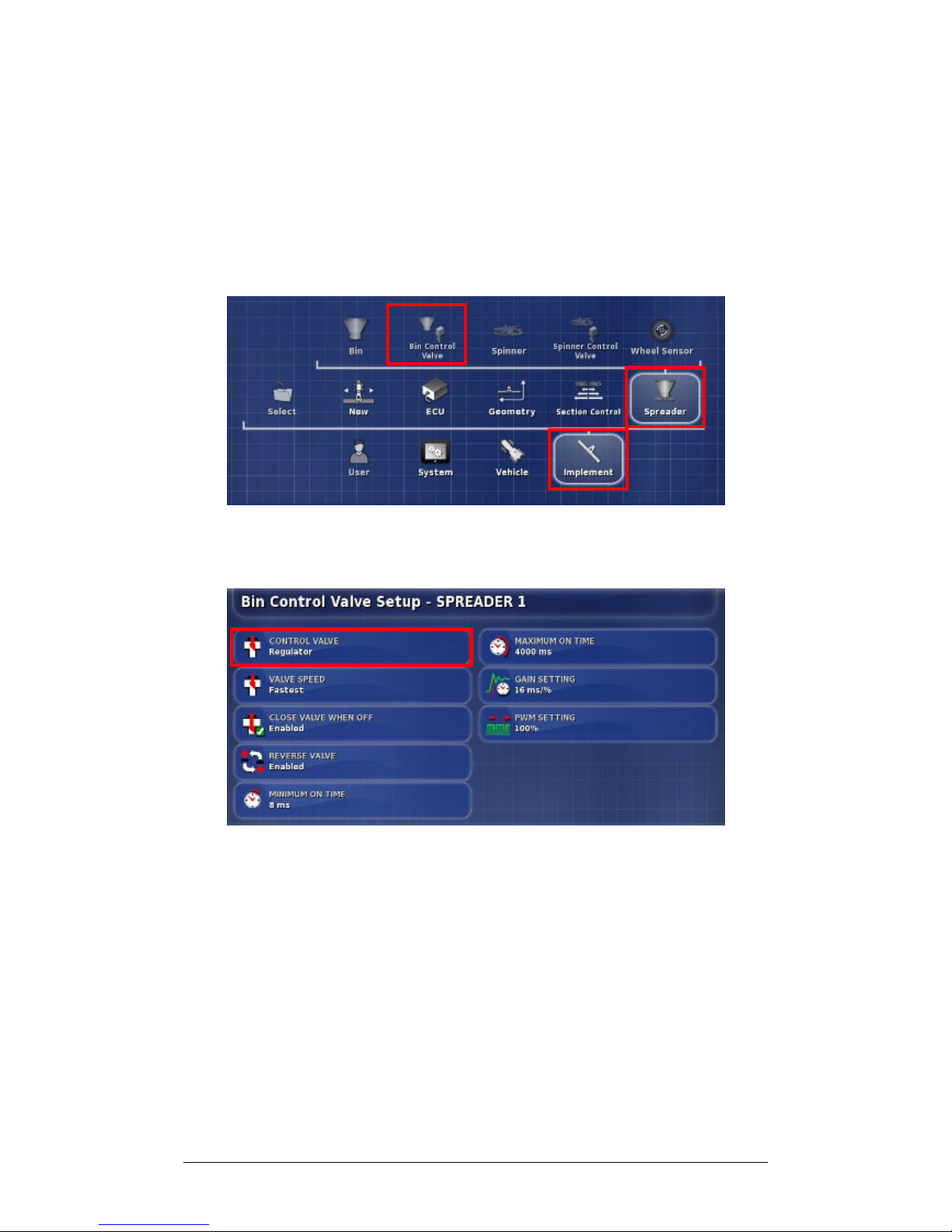
1. Select Implement, Spreader and select Bin Control
Valve.
2. Select Control Valve.
Page 54
Chapter 3 - Spreader Controller Setup 3.4 Setting up Control Valve (Regulator)
X30 Spreader Controller
3-15
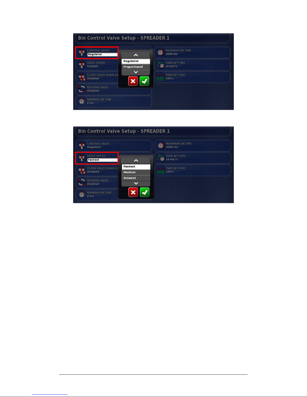
3. Choose Regulator and Confirm.
4. Select Valve Speed. The valve speed selected will
depend on the regulator valve fitted to the machine and
how fast this valve can operate.
5. Choose speed and Confirm. The chosen speed will affect
the options offered in some of the following steps.
Page 55
Chapter 3 - Spreader Controller Setup 3.4 Setting up Control Valve (Regulator)
X30 Spreader Controller
3-16
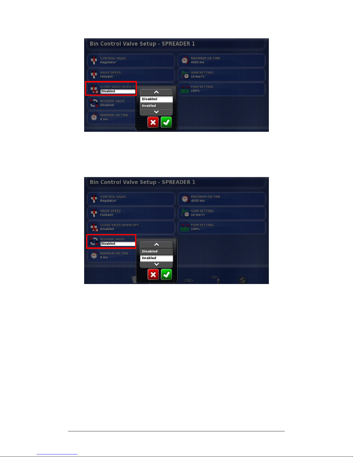
6. To close the valve when the spreader or bin is not in use,
Select Close Valve When Off.
7. Choose Enabled and Confirm.
8. In some cases the valve in a bin may have been wired to
work in the opposite direction. To allow the valve to
work in reverse, select Reverse Valve.
9. Choose Enabled and Confirm.
Page 56
Chapter 3 - Spreader Controller Setup 3.4 Setting up Control Valve (Regulator)
X30 Spreader Controller
3-17
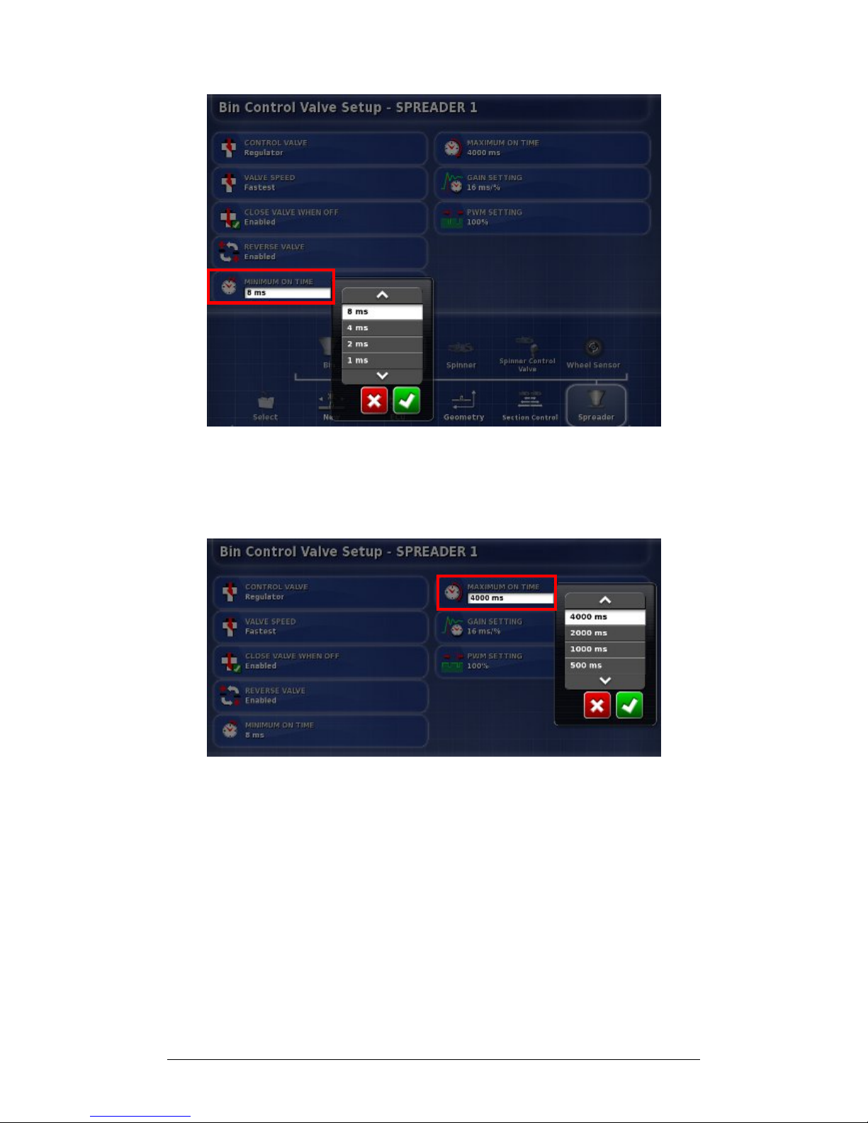
10. Select Minimum On Time. This sets the minimum time
to apply power to start the actuator moving.
11. Set minimum time and Confirm.
12. Repeat for Maximum On Time if necessary. This sets the
maximum time to apply power to move the actuator to
position. Changing this setting is only recommended for
valves that tend to respond too quickly.
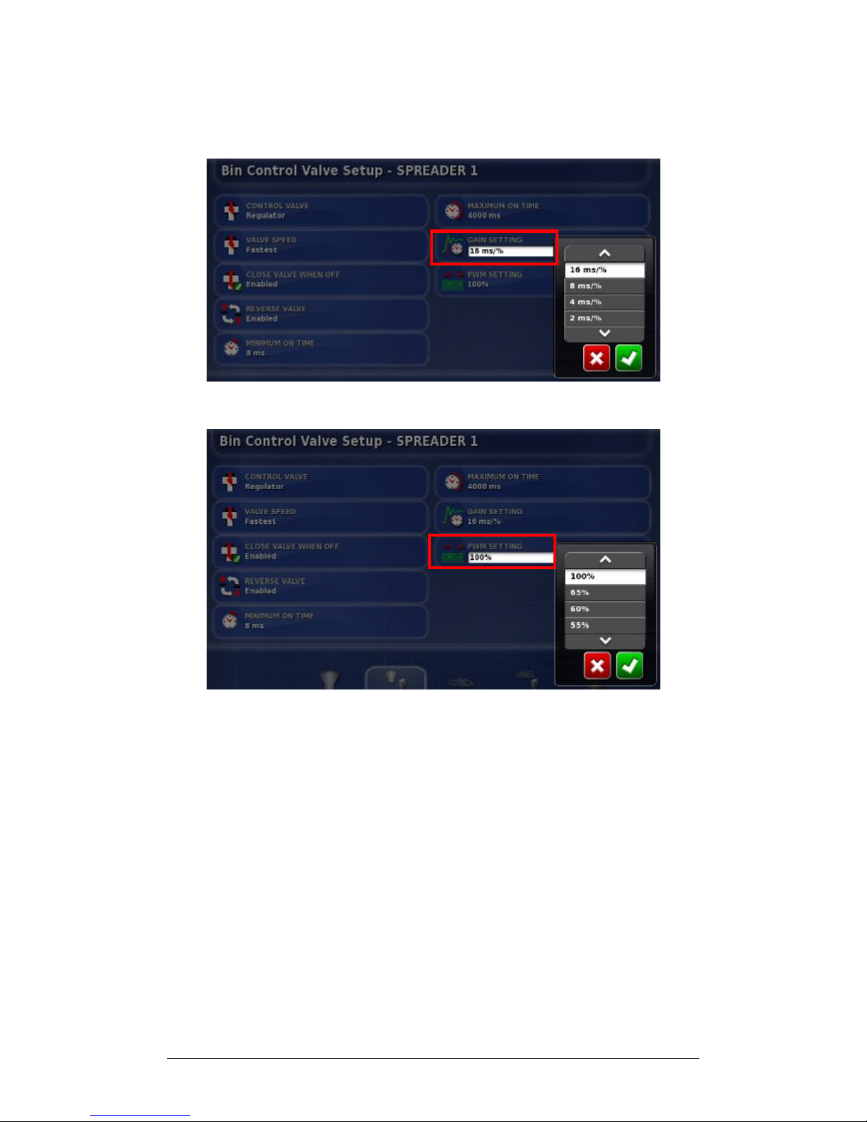
13. To change the gain setting, select Gain Setting. This will
set how quickly the controller will try to achieve the
required rate. If set too high, the spreader may pass the
target rate and take time to adjust, searching for the right
Page 57
Chapter 3 - Spreader Controller Setup 3.4 Setting up Control Valve (Regulator)
X30 Spreader Controller
3-18
level. Find the best gain percentage for the equipment
being used.
14. Choose the setting and Confirm.
15. To change the minimum percentage of time for the Pulse
Width Modulation (PWM) to be active, select PWM
Setting. Reducing the PWM will limit the overall voltage
that is applied to the valve. This could limit the torque
ability of the regulator valve.
16. Choose the percentage and Confirm.
Page 58
Chapter 3 - Spreader Controller Setup 3.5 Setting up Spinners
X30 Spreader Controller
3-19
3.5 Setting up Spinners
Follow the steps to set up spinners.
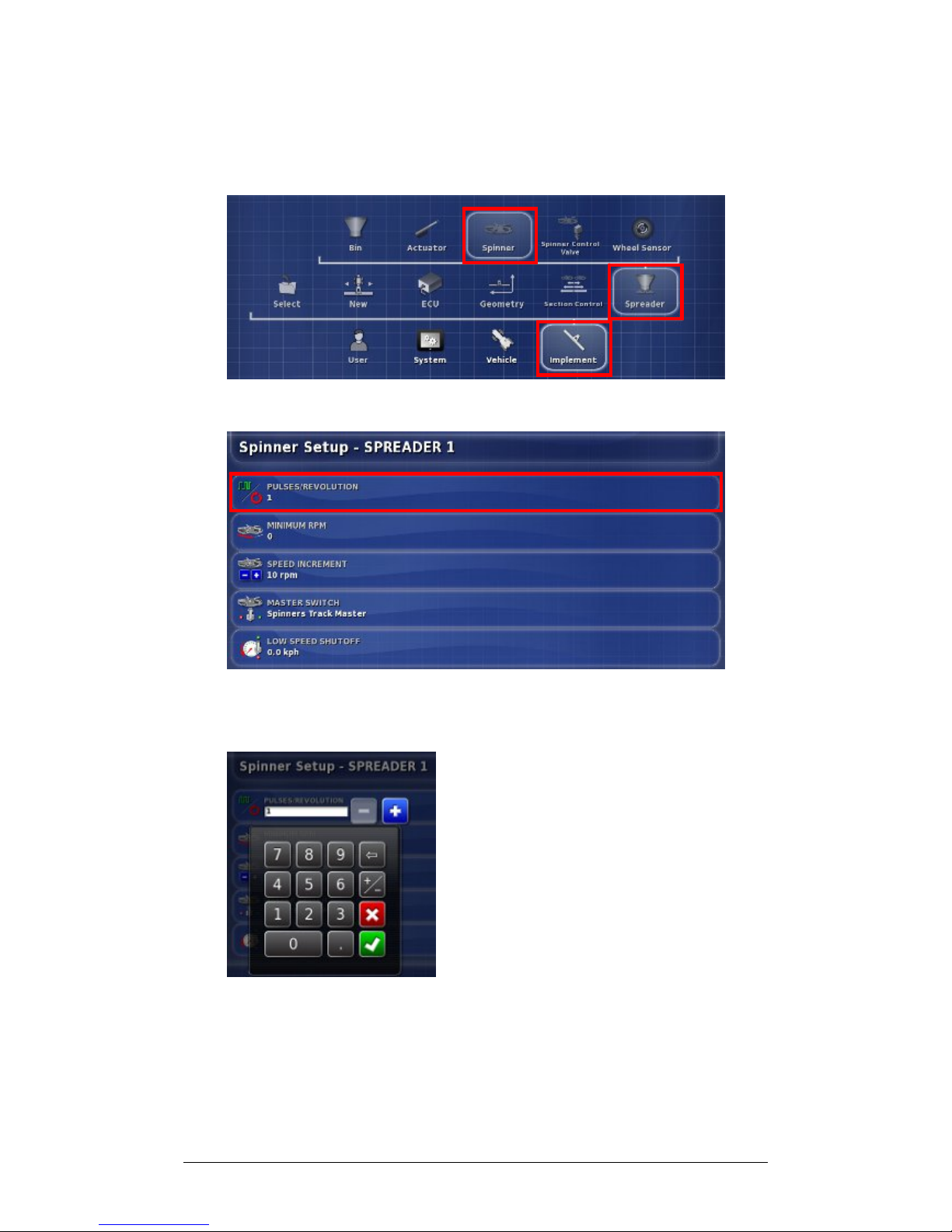
1. Select Implement, Spreader and Spinner.
2. To set the number of pulses recognized with each
revolution of the spinners, select Pulses/Revolution.
3. Enter the number of pulses and Confirm.
Page 59
Chapter 3 - Spreader Controller Setup 3.5 Setting up Spinners
X30 Spreader Controller
3-20
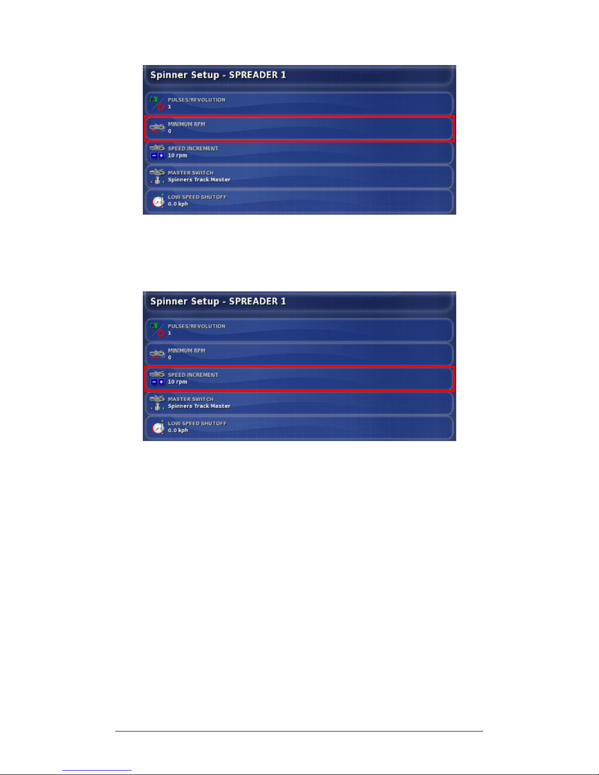
4. To set the minimum speed for spinners for auto control,
select Minimum RPM.
5. Enter the minimum RPM and Confirm.
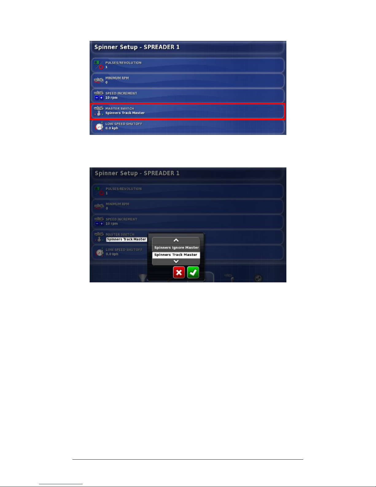
6. To set the size of incremental changes in spinner speed,
select Speed Increment.
7. Enter the preferred increment size and Confirm.
Page 60
Chapter 3 - Spreader Controller Setup 3.5 Setting up Spinners
X30 Spreader Controller
3-21
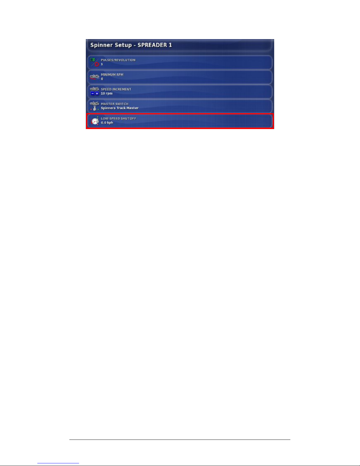
8. To link the operation of individual spinners to the
Spreader Master Switch, select Master Switch.
9. Choose Spinners Track Master (Master Switch will turn
spinners on and off) or Spinners Ignore Master and
Confirm.
Page 61
Chapter 3 - Spreader Controller Setup 3.5 Setting up Spinners
X30 Spreader Controller
3-22
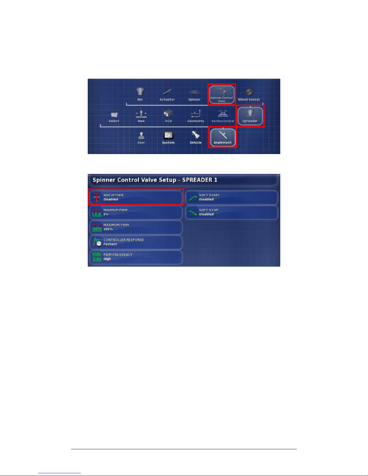
10. To set the vehicle’s low speed that will turn off the
spinners automatically, select Low Speed Shutoff.
11. Enter the shutoff speed and Confirm.
Page 62
Chapter 3 - Spreader Controller Setup 3.6 Setting up Spinner Control Valves
X30 Spreader Controller
3-23
3.6 Setting up Spinner Control Valves
Follow the steps to set up spinner control valves.
1. Select Spinner Control Valve.
2. To enable or disable valve dither, select Add Dither.
Dither makes the valve vibrate slightly to help prevent
sticking. Do not enable dither if using Sauer Danfoss
PWM Valves.
3. Choose Enabled and Confirm.
Page 63
Chapter 3 - Spreader Controller Setup 3.6 Setting up Spinner Control Valves
X30 Spreader Controller
3-24
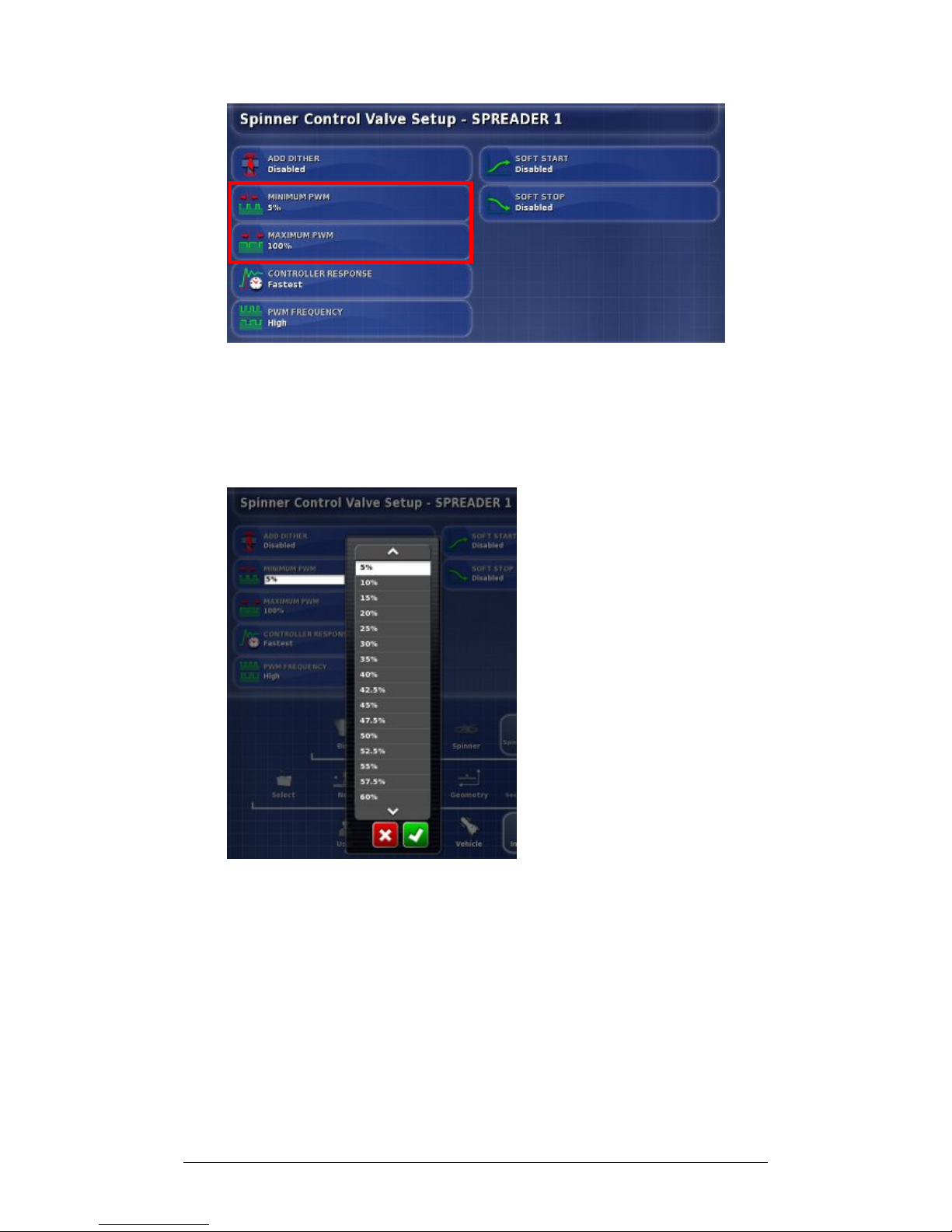
4. To set the minimum PWM (usually approximately 25%),
select Minimum PWM. Minimum PWM is the minimum
amount of power required to allow the valve to respond.
Anything under this figure the valve will not respond.
5. Choose percentage and Confirm.
6. Select Maximum PWM. Anything over this figure and
the valve speed will not increase. Choose percentage and
Confirm.
Page 64
Chapter 3 - Spreader Controller Setup 3.6 Setting up Spinner Control Valves
X30 Spreader Controller
3-25
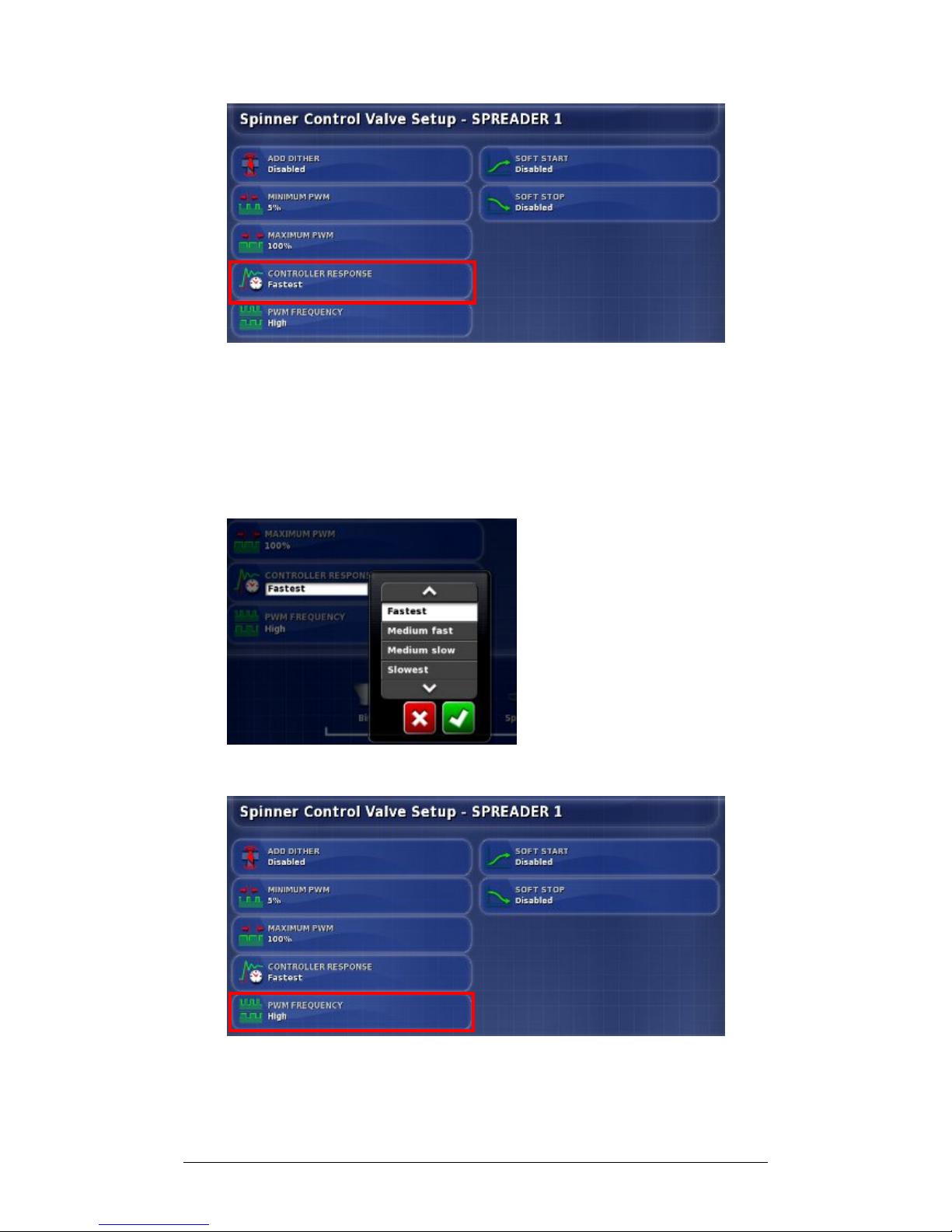
7. Select Controller Response. This will set how quickly the
spreader will try to achieve the required spinner speed. If
set too high, the spreader may pass the target speed and
take time to adjust, searching for the right level. Find the
best response speed for the equipment being used.
8. Choose speed and Confirm.
9. To set the PWM Frequency, select PWM Frequency.
Page 65
Chapter 3 - Spreader Controller Setup 3.6 Setting up Spinner Control Valves
X30 Spreader Controller
3-26
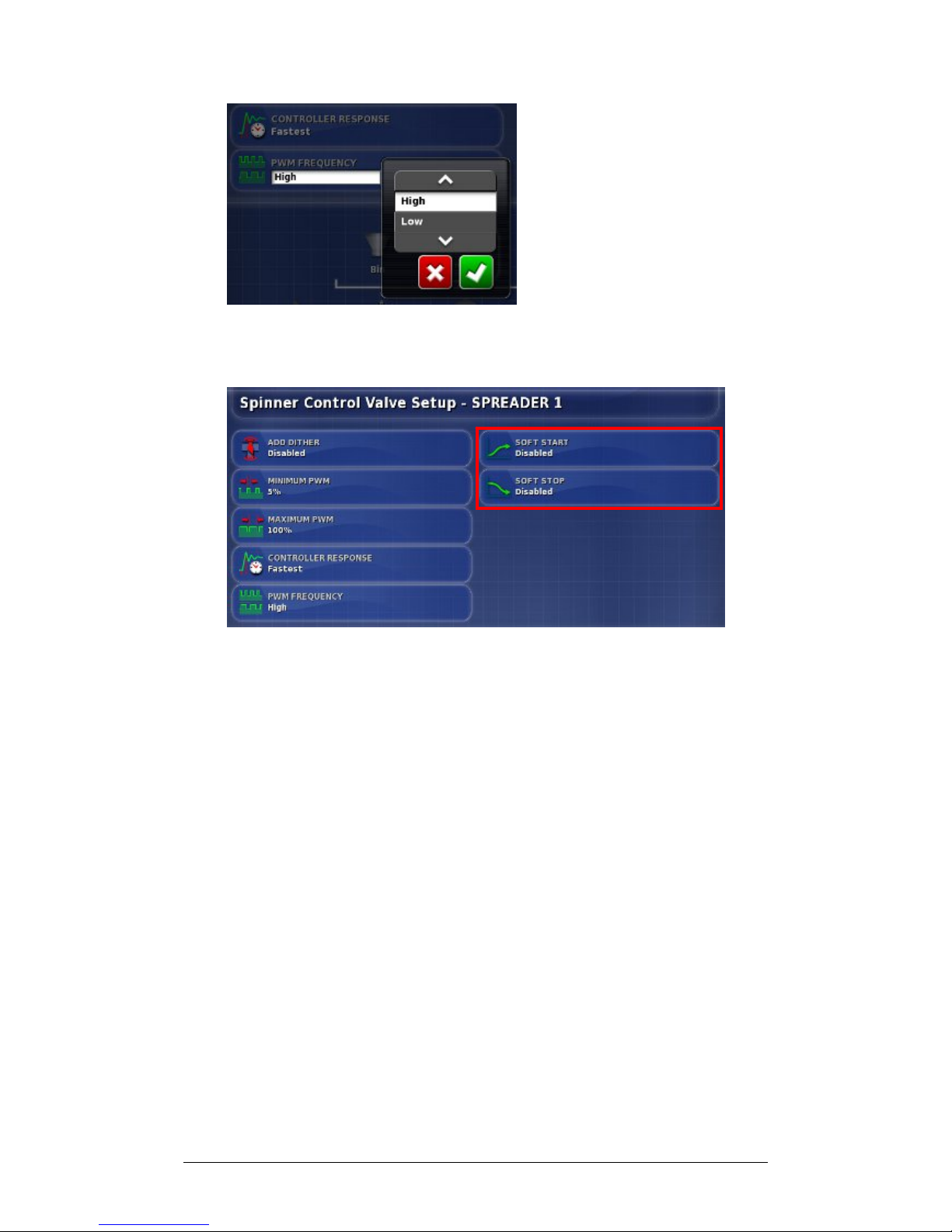
10. Choose frequency (high is faster and low is slower) and
Confirm.
11. To allow gradual increase in the valve power when the
valve is activated, select Soft Start.
12. Choose Enabled and Confirm.
13. To allow gradual decrease in the valve power when the
valve is de-activated, select Soft Stop, choose Enabled
and Confirm.
Page 66
Chapter 3 - Spreader Controller Setup 3.7 Setting up Wheel Sensor
X30 Spreader Controller
3-27
3.7 Setting up Wheel Sensor
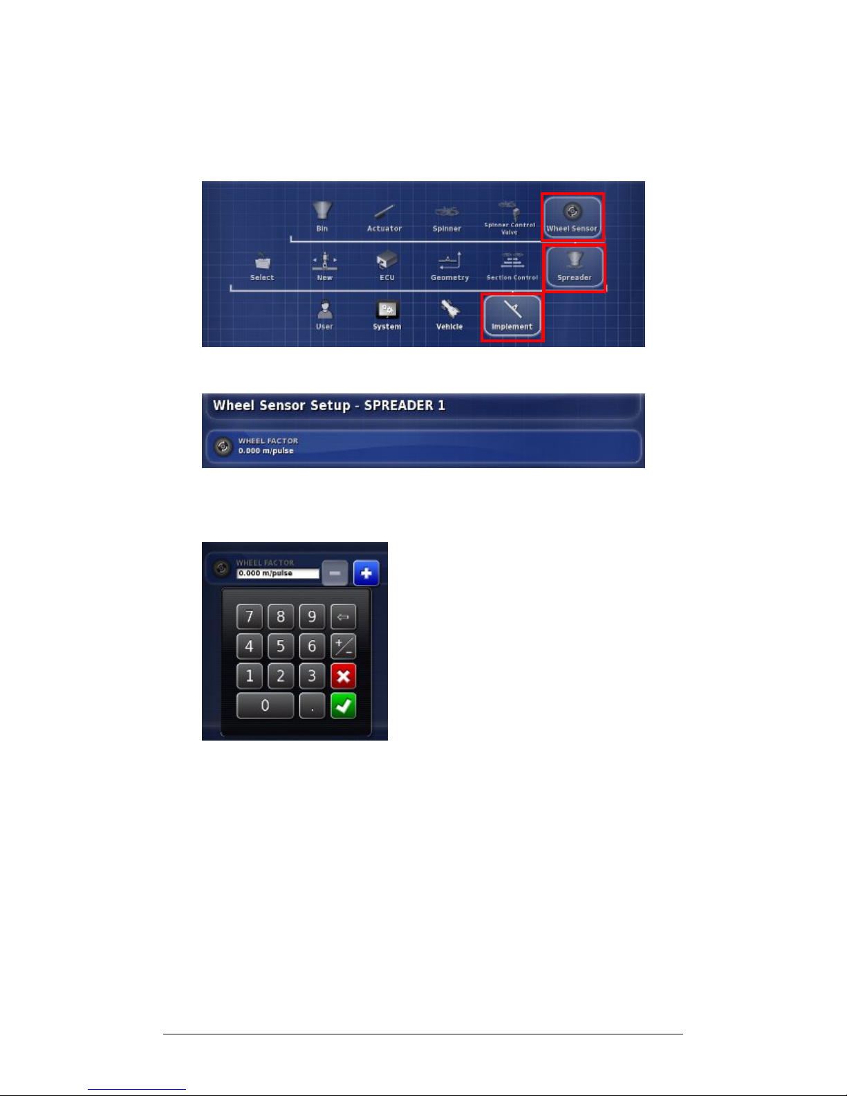
Follow the steps to set up the Wheel Sensor.
1. Select Wheel Sensor.
2. Select Wheel Factor. This sets how many meters per
pulse so that the wheel sensor can measure distances.
3. Enter the wheel factor and Confirm.
Page 67
Chapter 3 - Spreader Controller Setup 3.8 Setting Alarms
X30 Spreader Controller
3-28
3.8 Setting Alarms
Follow the steps to set up the Alarms. The alarm can be
enabled for all alarms or individual alarms. Use the All
Spreader Alarms option to universally enable or disable all
Spreader alarms.
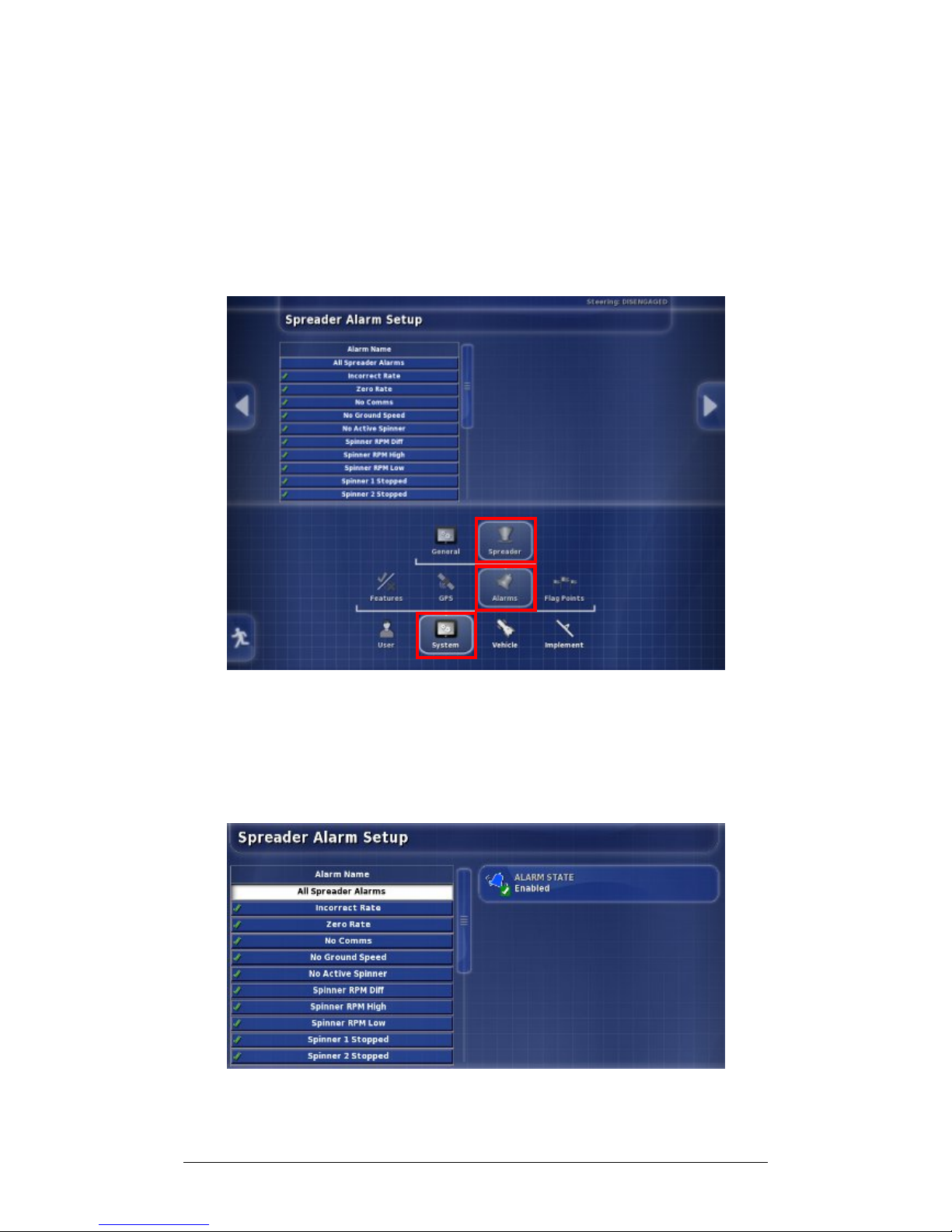
1. Select System, Alarms and select Spreader.
2. To enable all alarms for the spreader, select All Spreader
Alarms. This enables all alarms. Alarms that need more
information set are shown below.
3. Select Alarm State.
Page 68
Chapter 3 - Spreader Controller Setup 3.8 Setting Alarms
X30 Spreader Controller
3-29
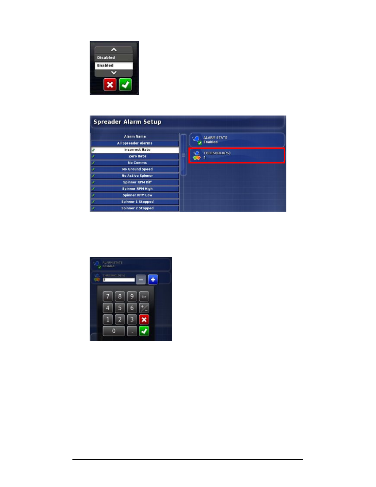
4. Choose Enabled (or Disabled) and Confirm.
5. Select Incorrect Rate. This alarm will sound and display
if the detected actual rate is different from the preset rate
by the threshold amount. Select Threshold.
6. Enter threshold percentage (lower % is more sensitive)
and Confirm.
Page 69
Chapter 3 - Spreader Controller Setup 3.8 Setting Alarms
X30 Spreader Controller
3-30
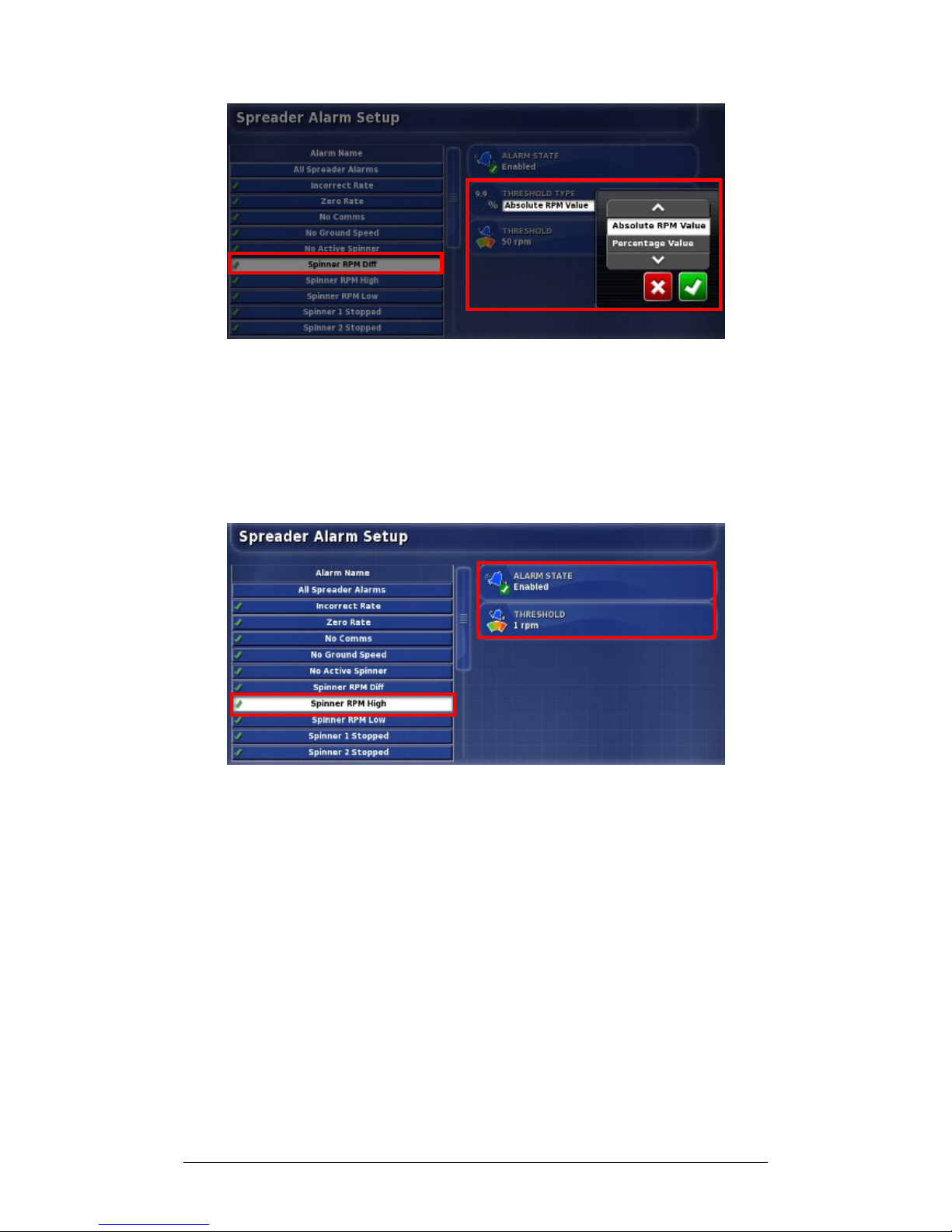
7. Select Spinner RPM Diff. This alarm will sound and
display if the detected spinners’ rates differ from each
other by a set amount. Select Threshold Type and
Confirm.
8. Select Threshold, enter the threshold value and Confirm.
9. Select Spinner RPM High. This alarm will sound and
display if the detected actual spinner RPM exceeds the
set threshold. Select Threshold, enter the maximum
threshold and Confirm.
10. Select Spinner RPM Low, select Threshold, enter the
minimum threshold and Confirm.
Page 70
Chapter 3 - Spreader Controller Setup 3.8 Setting Alarms
X30 Spreader Controller
3-31
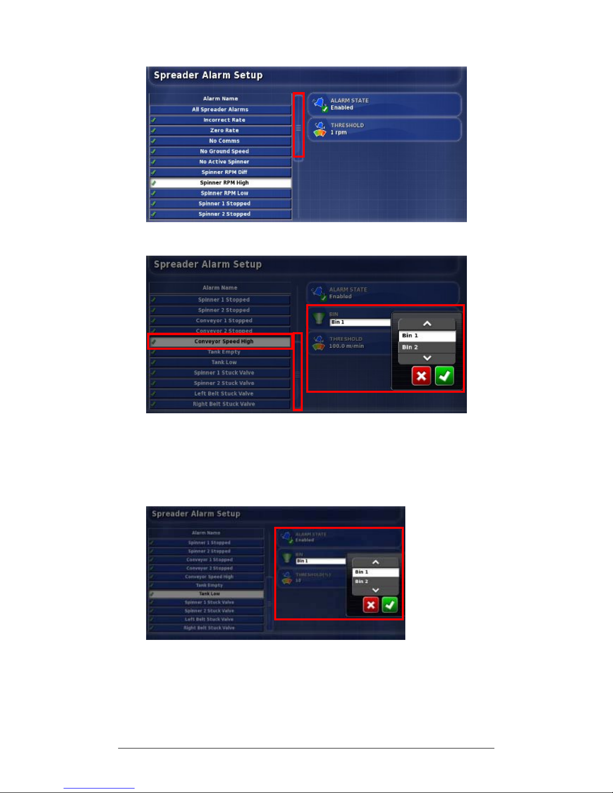
11. Use the scroll bar to see other alarms.
12. If using a belt driven spreader, select Conveyor Speed
High. This alarm will sound and display if the speed of
the conveyor belt is greater than the threshold. This
alarm is only offered for belt driven spreaders.
13. Select Bin, choose the bin and Confirm.
14. Select Threshold, enter the threshold. Confirm.
15. Repeat steps 12-14 for other bins.
Page 71
X30 Spreader Controller
4-1
Chapter 4 - Operations
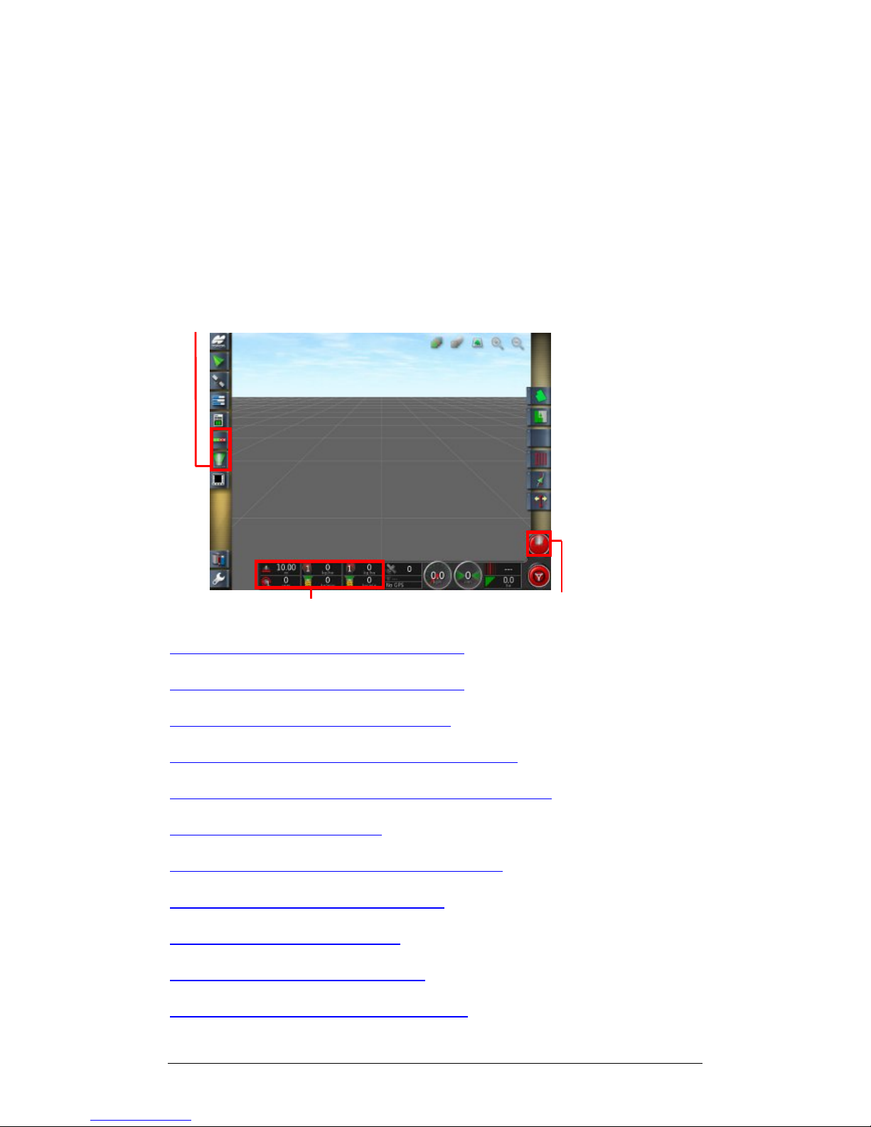
Once setup is complete, the Auto Section Control (if
enabled) and Spreader Controller icons appear on the
Navigation Bar and Spreader Controller information is
added to the Dashboard. The Spreader Master Switch
appears in the lower right corner.
Auto Section Control and Spreader Controller icons
Spreader Dashboard Spreader Master Switch
4.1 Using the Spreader Dashboard
4.2 Opening Auto Section Control
4.3 Opening Spreader Controller
4.4 Choosing / Changing Bins and Rates
4.5 Choosing / Changing a Product and Rate
4.6 Monitoring Statistics
4.7 Choosing and Changing Sub Areas
4.8 Configuring and Calibrating
4.9 Managing the Spinners
4.10 Using the Master Switch
4.11 Using Map Views and Layers
Page 72
Chapter 4 - Operations 4.1 Using the Spreader Dashboard
X30 Spreader Controller
4-2
4.1 Using the Spreader Dashboard
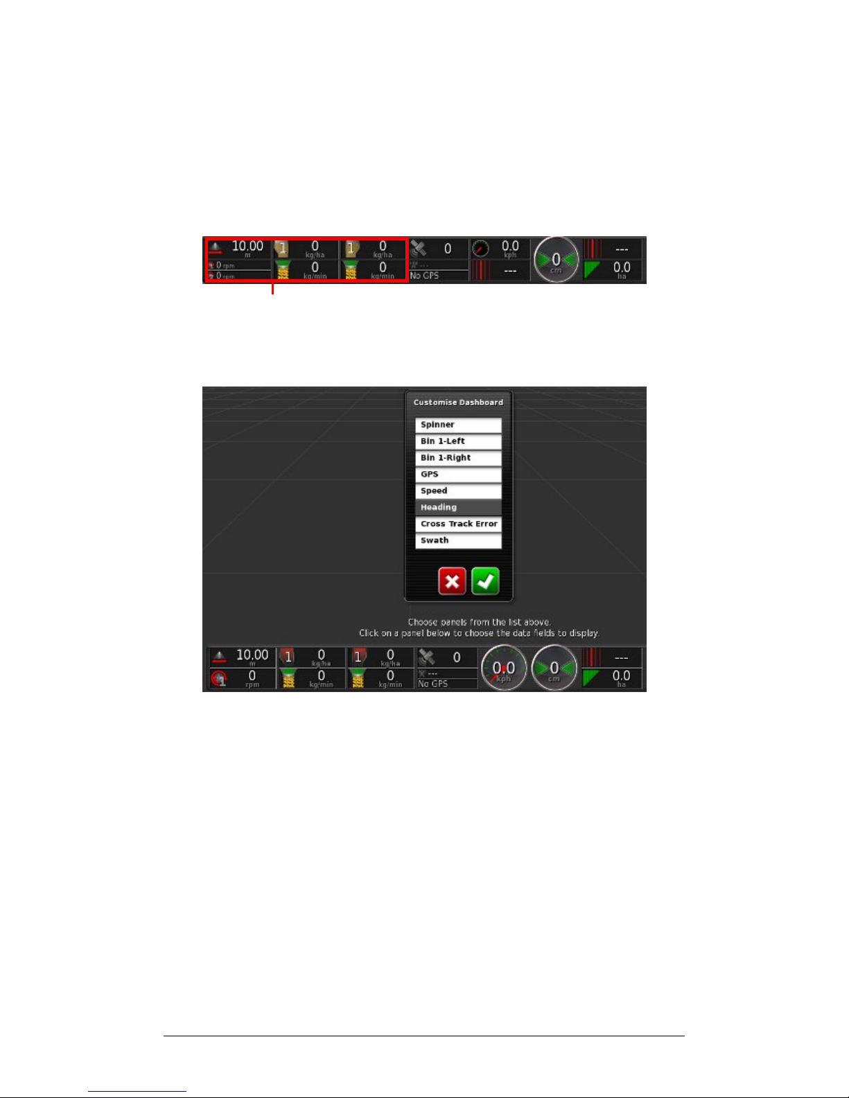
Spreader information is added to the Dashboard. The
example below shows the default display for a split bin
spreader.
Spreader Dashboard
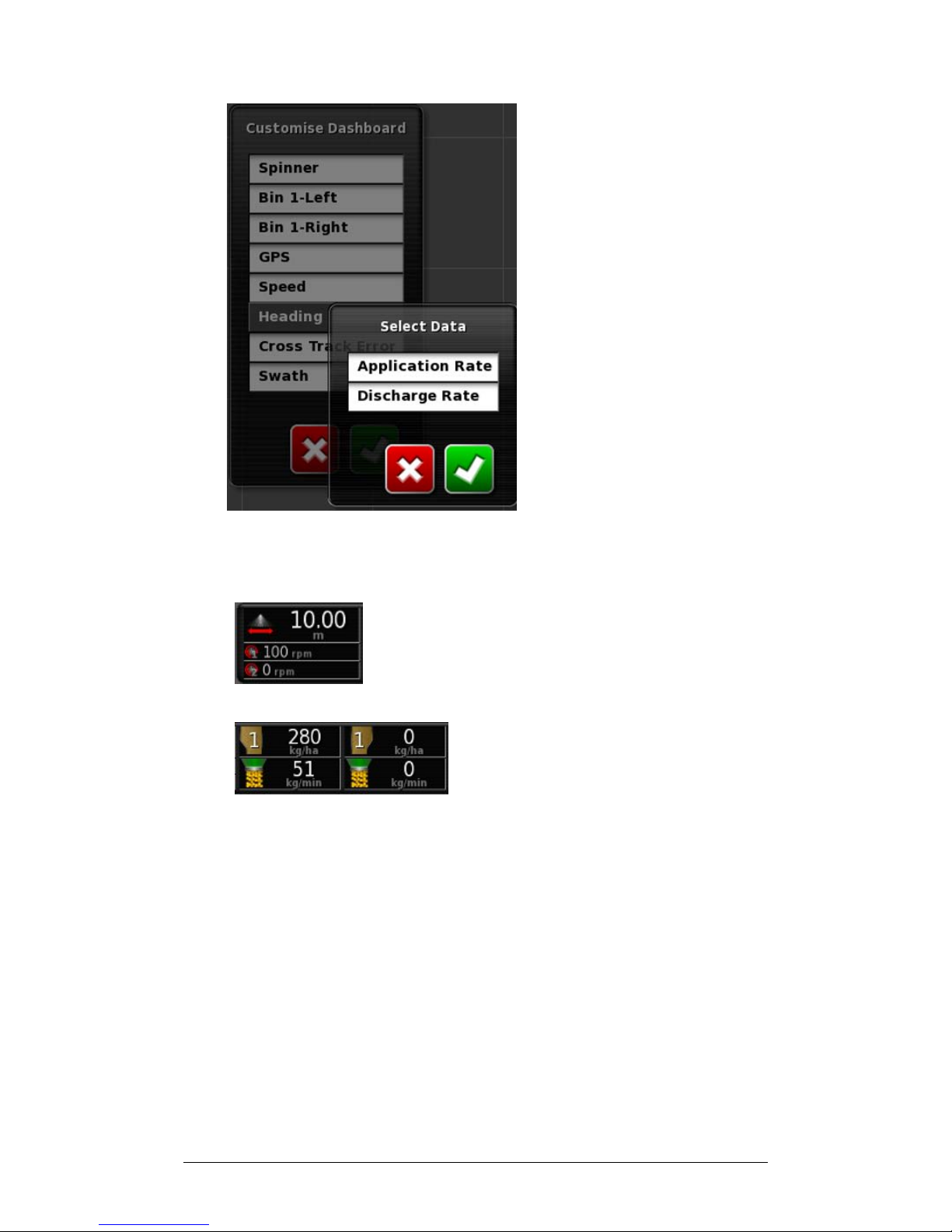
1. Select any part of the dashboard to customize the
information it displays.
2. Choose the information to display (showing white).
3. To choose the information to appear in a particular
Dashboard Panel, select the panel again.
Page 73
Chapter 4 - Operations 4.1 Using the Spreader Dashboard
X30 Spreader Controller
4-3
4. Choose the information to appear and Confirm.
5. Monitor information.
This displays spinner information
and spreading width.
This displays bin and rate
information for a single split bin. If
two bins are used, the panel will
show Tanks 1 and 2.
Page 74
Chapter 4 - Operations 4.2 Opening Auto Section Control
X30 Spreader Controller
4-4
4.2 Opening Auto Section Control
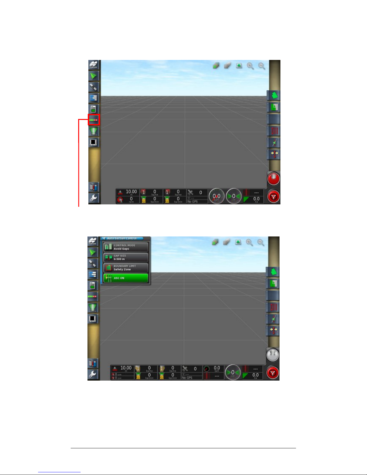
Auto Section Control
1. Select Auto Section Control.
Use the mini-view to adjust control mode, gaps,
boundary limits and turn Auto Section Control on/off.
Page 75
Chapter 4 - Operations 4.2 Opening Auto Section Control
X30 Spreader Controller
4-5
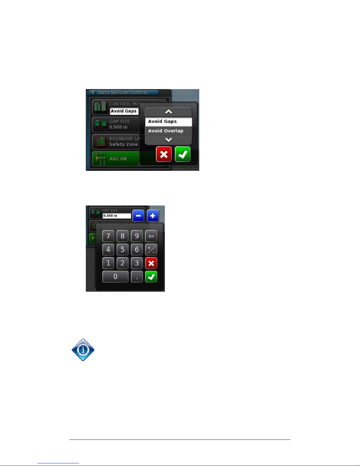
2. Select Control Mode to avoid overlap or avoid gaps. If
Avoid Gaps is chosen, some overlap of application is
likely near boundaries. If Avoid Overlap is chosen, there
may be some spaces where product is not applied.
3. Choose and Confirm.
4. Select Gap Size to adjust the size of gaps, if needed.
5. Enter the preferred gap size and Confirm.
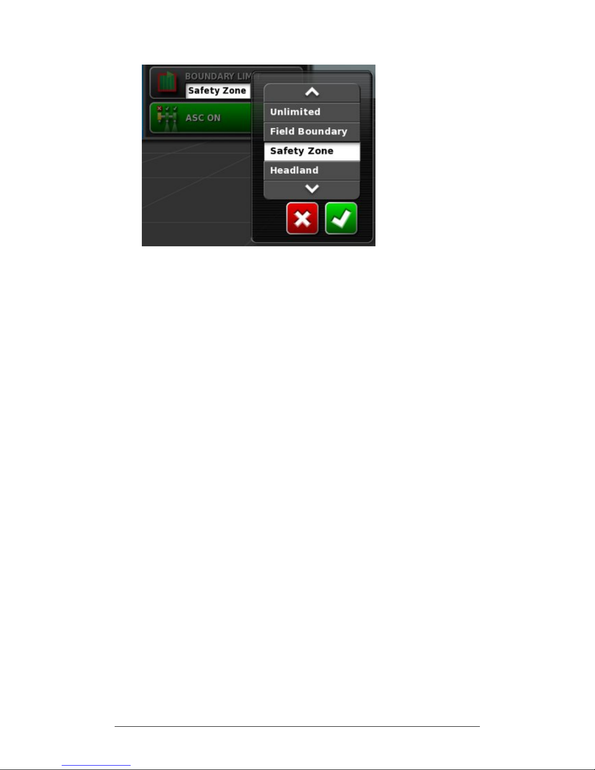
6. Select Boundary Limit. This sets which type of boundary
limit will turn off spreading using Auto Section Control.
Field Boundary and Headland are defined using the Field
Menu on the Operations Screen. Refer to the Guidance and
Auto Steering Operator’s Manual for more information on
these.
Safety Zone reduces width of spreading by half a swath
width from the boundary to prevent overspread.
Page 76
Chapter 4 - Operations 4.2 Opening Auto Section Control
X30 Spreader Controller
4-6
7. Choose the preferred boundary limit and Confirm.
Page 77
Chapter 4 - Operations 4.3 Opening Spreader Controller
X30 Spreader Controller
4-7
4.3 Opening Spreader Controller
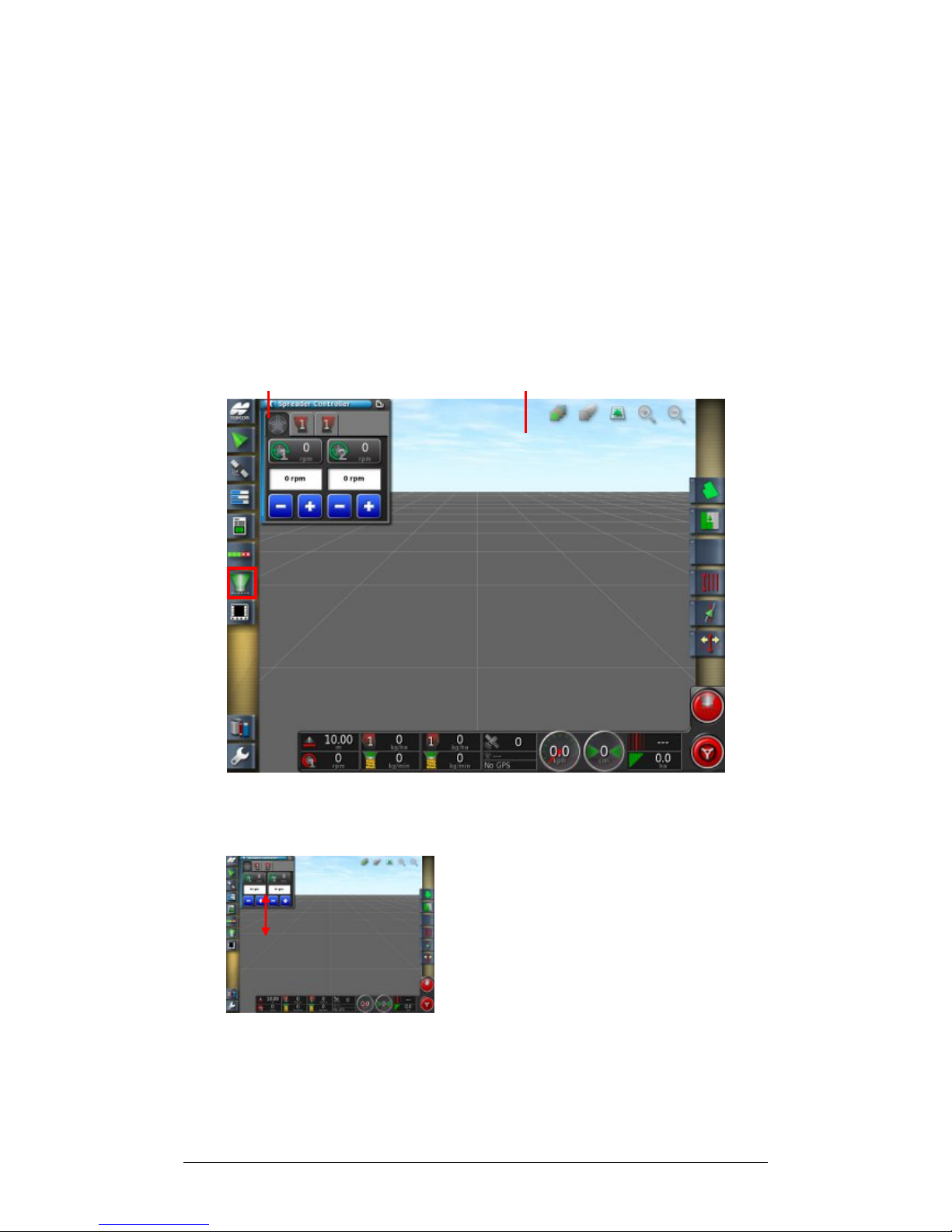
The Spreader Controller interface can appear either in a mini-
view or in full screen. When the Spreader Controller is in
full screen, the Guidance Map can appear as a mini-view, so
that the operator can still monitor guidance.
1. Select Spreader Controller to open a mini-view of the
Spreader Controller.
Mini-view Full Screen Guidance Map
Use the mini-view to monitor status, adjust spread rate or
spinner speed or switch between bins.
To move the mini-view to another
position on the screen, slide up or
down.
Page 78
Chapter 4 - Operations 4.3 Opening Spreader Controller
X30 Spreader Controller
4-8
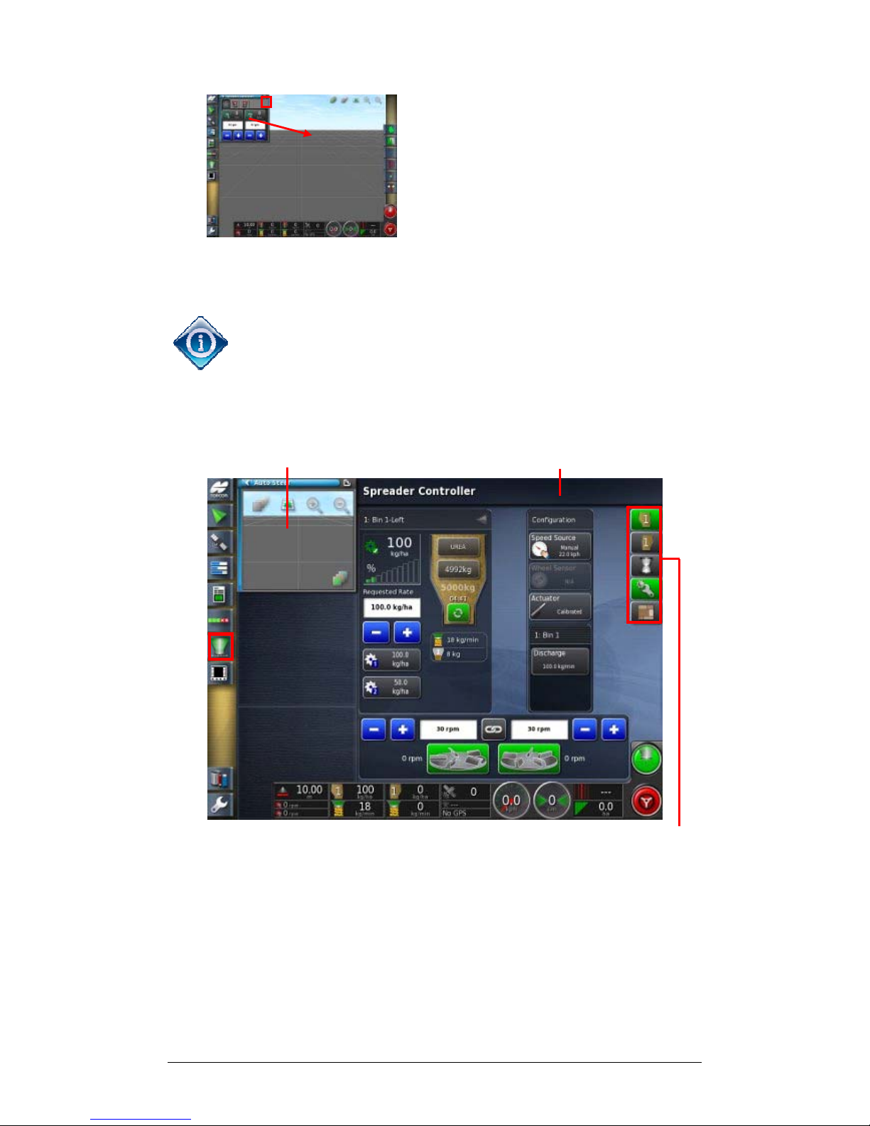
To open the Spreader Controller to
full screen, touch anywhere in the
mini-view and slide towards the full
screen, or use Maximize (top right).
The Spreader Controller full screen interface shows a
number of Panels.
If desired, select Spreader Controller again to display full
screen and a mini-view of the Spreader Controller at the
same time.
2. Select which panels to show using the Spreader Toolbar.
Mini-view guidance Spreader Panels
Spreader Toolbar
3. Slide panels to rearrange the interface.
Page 79
Chapter 4 - Operations 4.4 Choosing / Changing Bins and Rates
X30 Spreader Controller
4-9
4.4 Choosing / Changing Bins and Rates
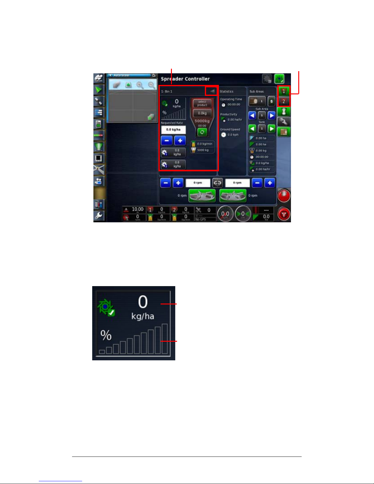
Bin Panel Bin Icons
1. Select Bin icons on the Spreader Tool Bar to open the
panel for the bin being used. Use the arrow (top right) to
expand and show product information.
2. Monitor the rate.
Actual Rate
Actuator Position or percentage of
maximum belt speed
Page 80
Chapter 4 - Operations 4.5 Choosing / Changing a Product and Rate
X30 Spreader Controller
4-10
4.5 Choosing / Changing a Product and Rate
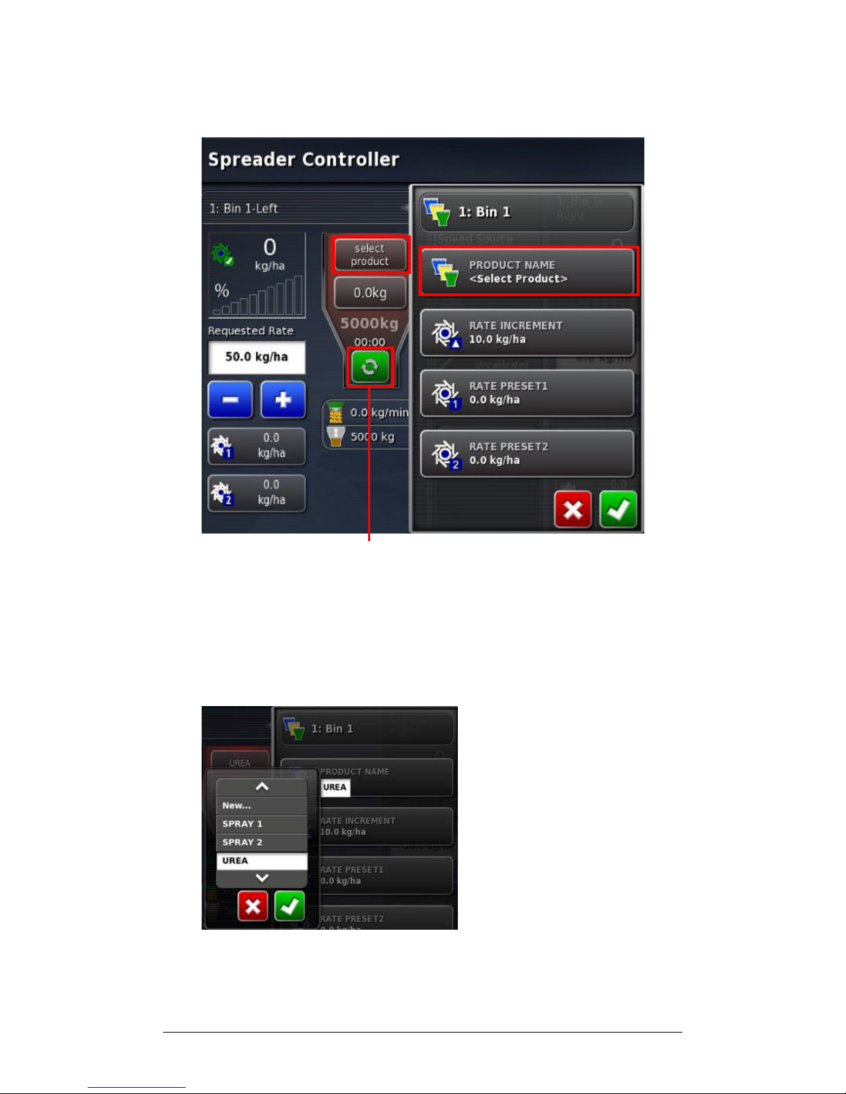
Bin On/Off
1. Select Bin On/Off to allow the bin to operate.
2. To choose or change the product being used, select
Select Product.
3. Select Product Name.
3a. Choose from existing products and Confirm.
OR
Page 81
Chapter 4 - Operations 4.5 Choosing / Changing a Product and Rate
X30 Spreader Controller
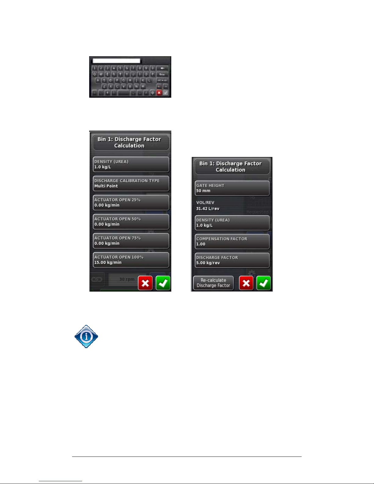
4-11
3b. Choose Create New and Confirm.
3c. Enter a name for the new product and Confirm.
Actuator Driven Belt Driven
4. To allow the system to calculate the rate accurately,
select and enter values to use in calculations.
DISCHARGE CALIBRATION TYPE
can be single or
multipoint. Single point assumes a linear variation in rate
(that is, 25% open means 25% product flow and 50% open
means 50% product flow). Multipoint allows values at
25%, 50% and 75% open for more accurate calculations.
COMPENSATION FACTOR
allows for variation overall.
For example, if the on-screen bin displays empty but the
actual bin is not quite empty (or the bin is empty and onscreen bin is not), the operator can set a compensation
factor to allow for this.
Page 82
Chapter 4 - Operations 4.5 Choosing / Changing a Product and Rate
X30 Spreader Controller
4-12
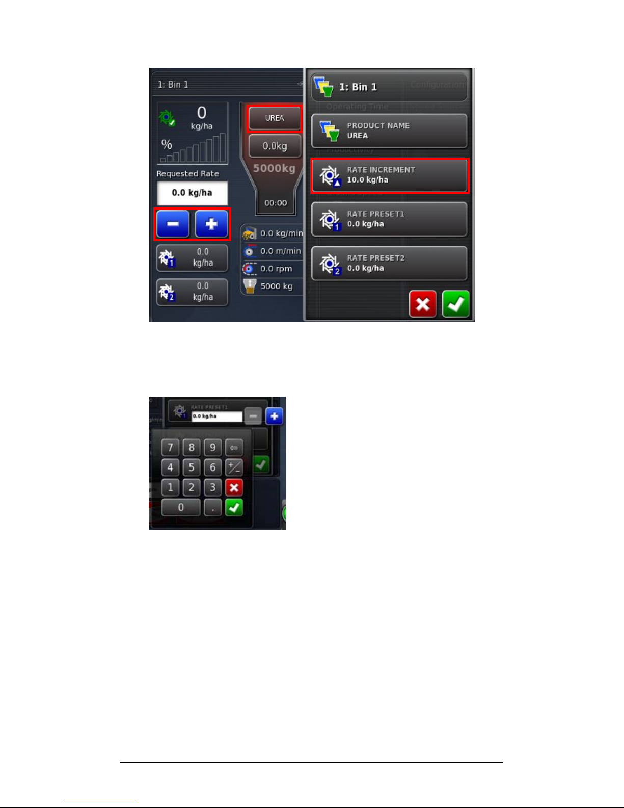
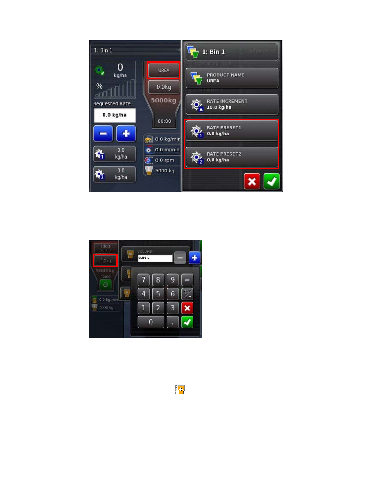
5. To set the rate increment for changes to the rate, select
Rate Increment. This is the amount that the rate will
change when the plus and minus symbols are used.
6. Enter the preferred rate and Confirm.
Page 83
Chapter 4 - Operations 4.5 Choosing / Changing a Product and Rate
X30 Spreader Controller
4-13
7. Select Rate Preset 1, enter the rate and Confirm.
8. Repeat for Rate Preset 2. Confirm to return to Spreader
Controller Panel.
9. Select Tank Fill and Volume. Enter the amount of
product in the bin and Confirm.
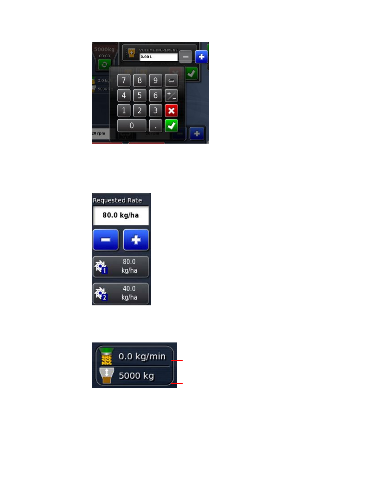
10. Select Volume Increment. This will set how much
volume is added when is selected.
Page 84
Chapter 4 - Operations 4.5 Choosing / Changing a Product and Rate
X30 Spreader Controller
4-14
11. Enter the increment and Confirm.
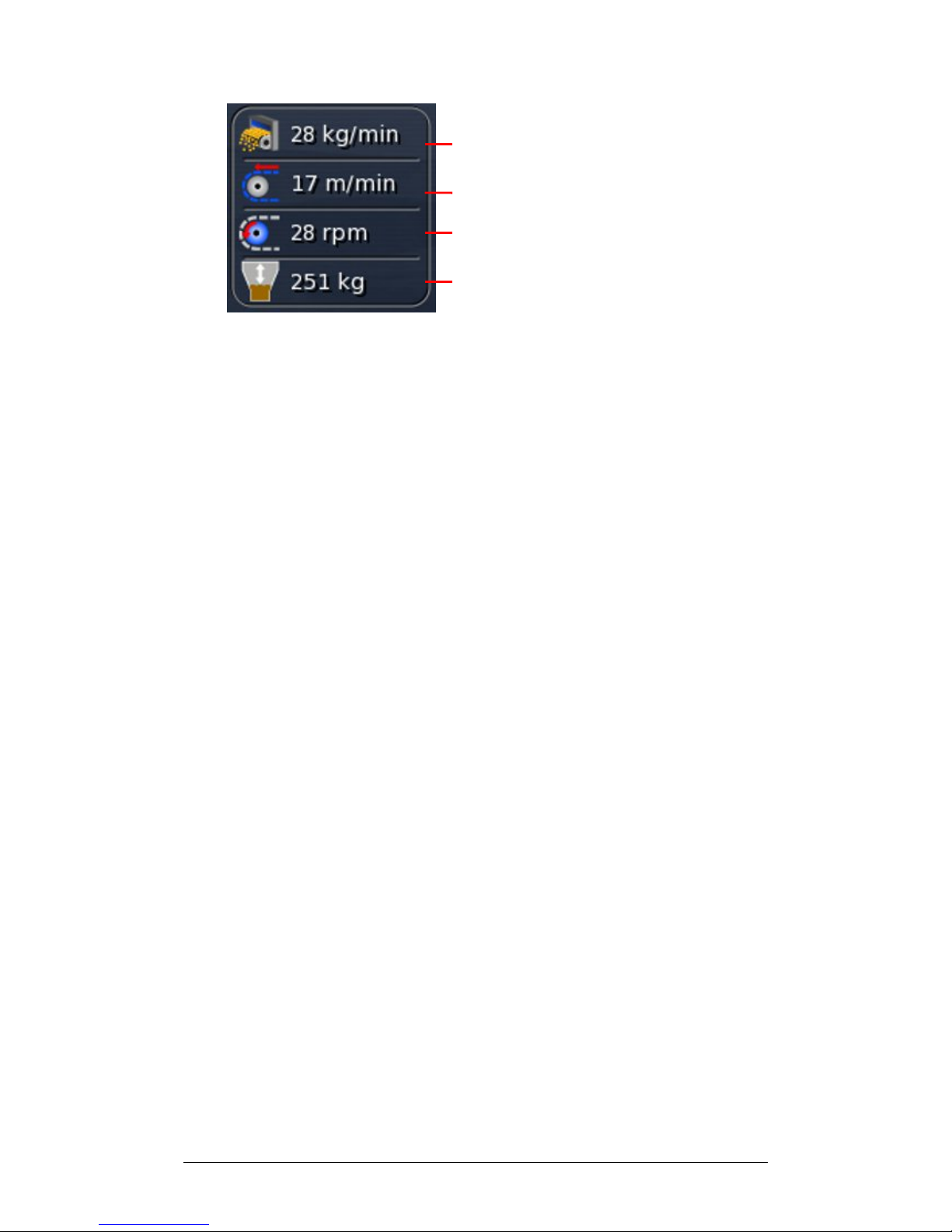
12. To change Requested Rate during operations, select
Preset Rate 1 or 2.
13. Use plus or minus to set or change the rate.
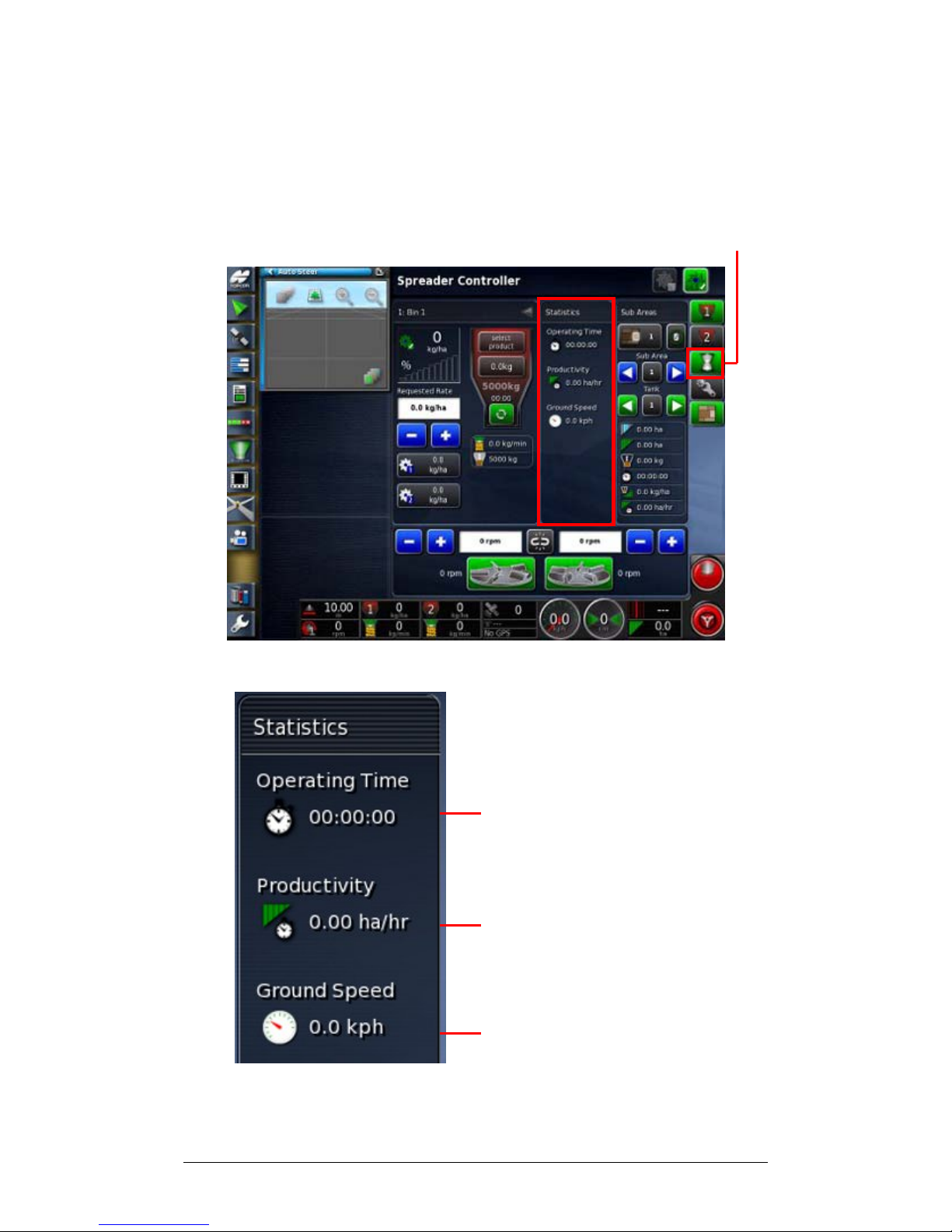
14. Monitor discharge rate and volume used.
Actuator Driven:
Discharge Rate
Volume Used
Page 85
Chapter 4 - Operations 4.5 Choosing / Changing a Product and Rate
X30 Spreader Controller
4-15
Belt Driven:
Discharge Rate
Belt Speed
Belt RPM
Volume Used
Page 86
Chapter 4 - Operations 4.6 Monitoring Statistics
X30 Spreader Controller
4-16
4.6 Monitoring Statistics
The following panel allows the operator to monitor
information during a job.
Statistics Icon
1. Select Statistics on the Spreader Toolbar.
Time Spent on the Job
Current Productivity
Current Ground Speed
Page 87
Chapter 4 - Operations 4.7 Choosing and Changing Sub Areas
X30 Spreader Controller
4-17
4.7 Choosing and Changing Sub Areas
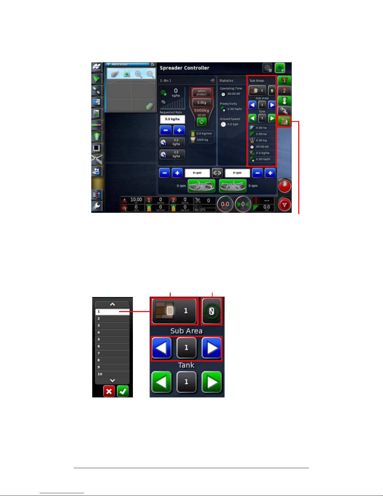
Sub Area Icon
1. Select Sub Area on the Spreader Toolbar to open the
Sub Area Panel. The top section of the panel can set sub
areas for the job so that information on those sub areas
can be recorded.
Active Sub Area Reset Sub Area
2. Select the Active Sub Area, choose a sub area to record
information about the job and Confirm.
Page 88
Chapter 4 - Operations 4.7 Choosing and Changing Sub Areas
X30 Spreader Controller
4-18
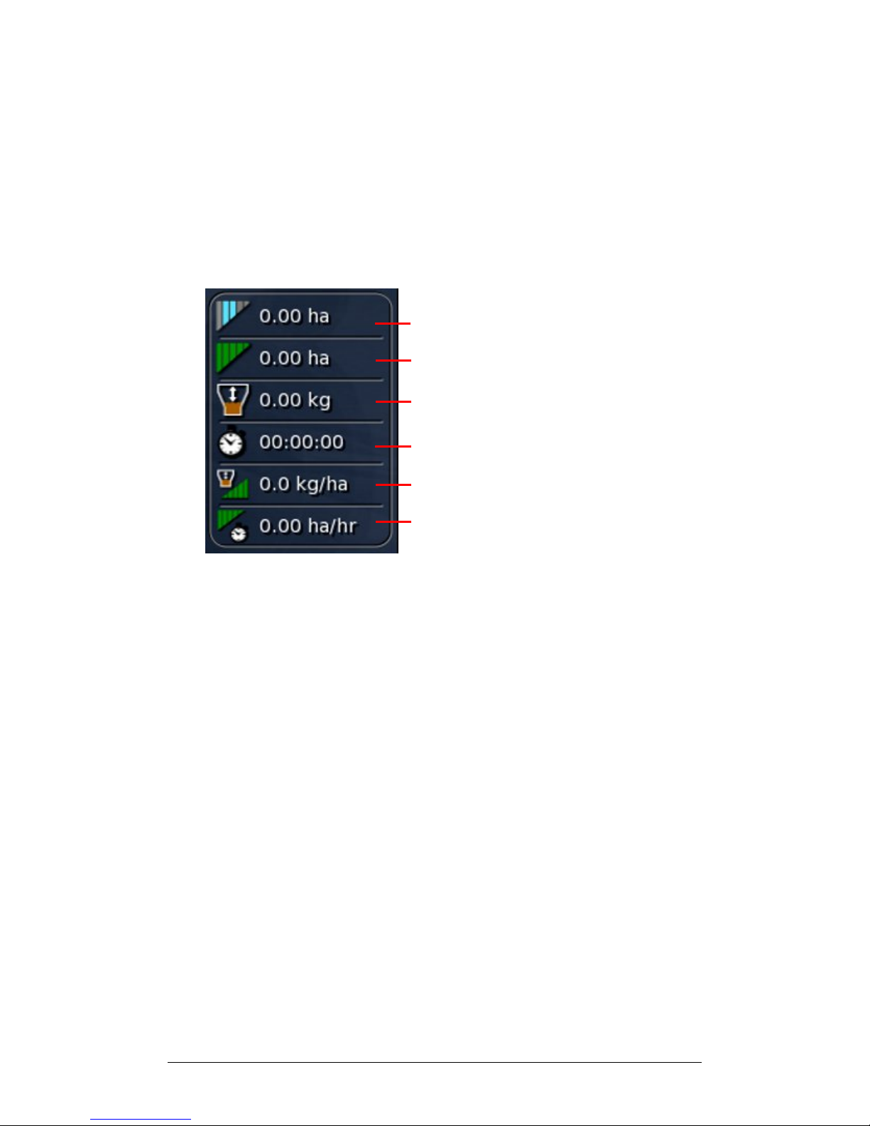
3. Use the blue arrows to view other sub areas. Note that
the system will continue to record information on the
active sub area.
4. Use the green arrows to choose between tanks.
5. Monitor progress on the active sub area in the lower half
of the panel.
Sectional Active Sub Area
Full Width Area
Volume Used
Total Time Spent on Current Job
Average Application Rate (Area)
Coverage Rate (Area/Time)
Page 89
Chapter 4 - Operations 4.8 Configuring and Calibrating
X30 Spreader Controller
4-19
4.8 Configuring and Calibrating
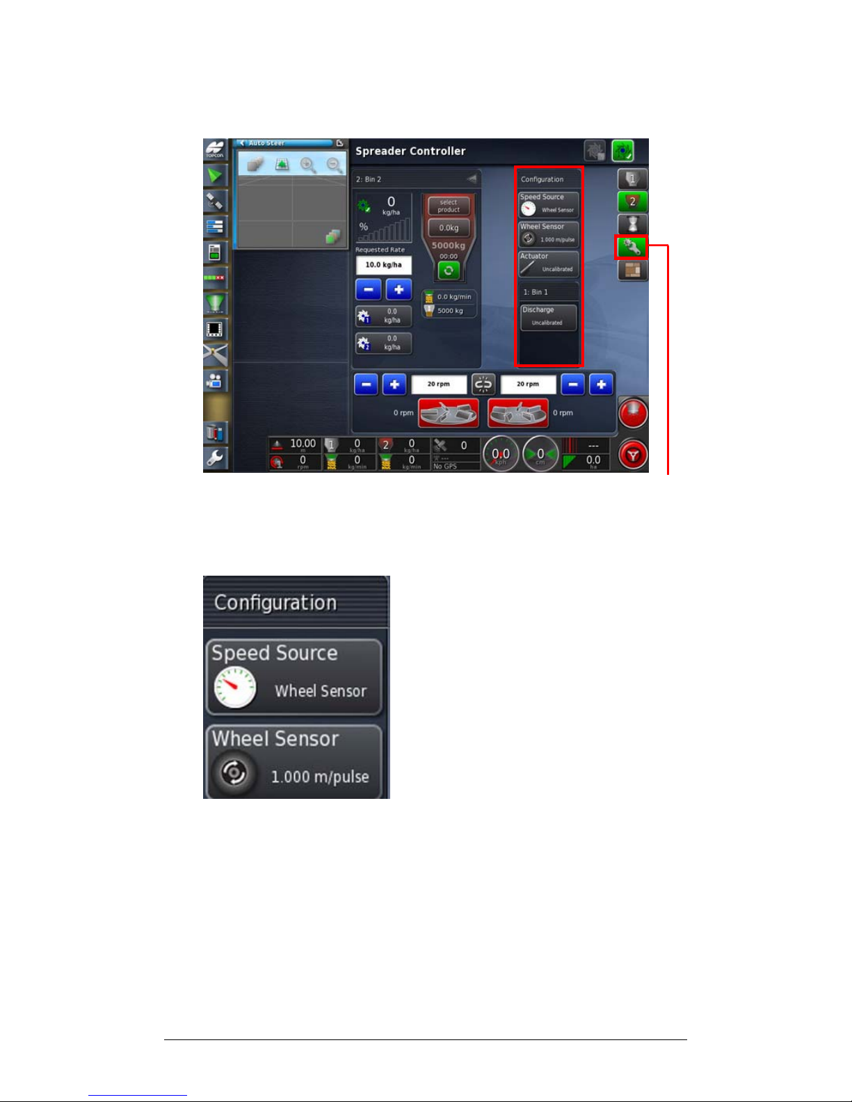
Configuration Icon
1. Select Configuration from the Spreader Toolbar to
open the Calibration Panel.
2. Select Speed Source to set how the system will measure
speed, (GPS, wheel sensor or remote). This will be used
to calculate application rates.
Page 90
Chapter 4 - Operations 4.8 Configuring and Calibrating
X30 Spreader Controller
4-20
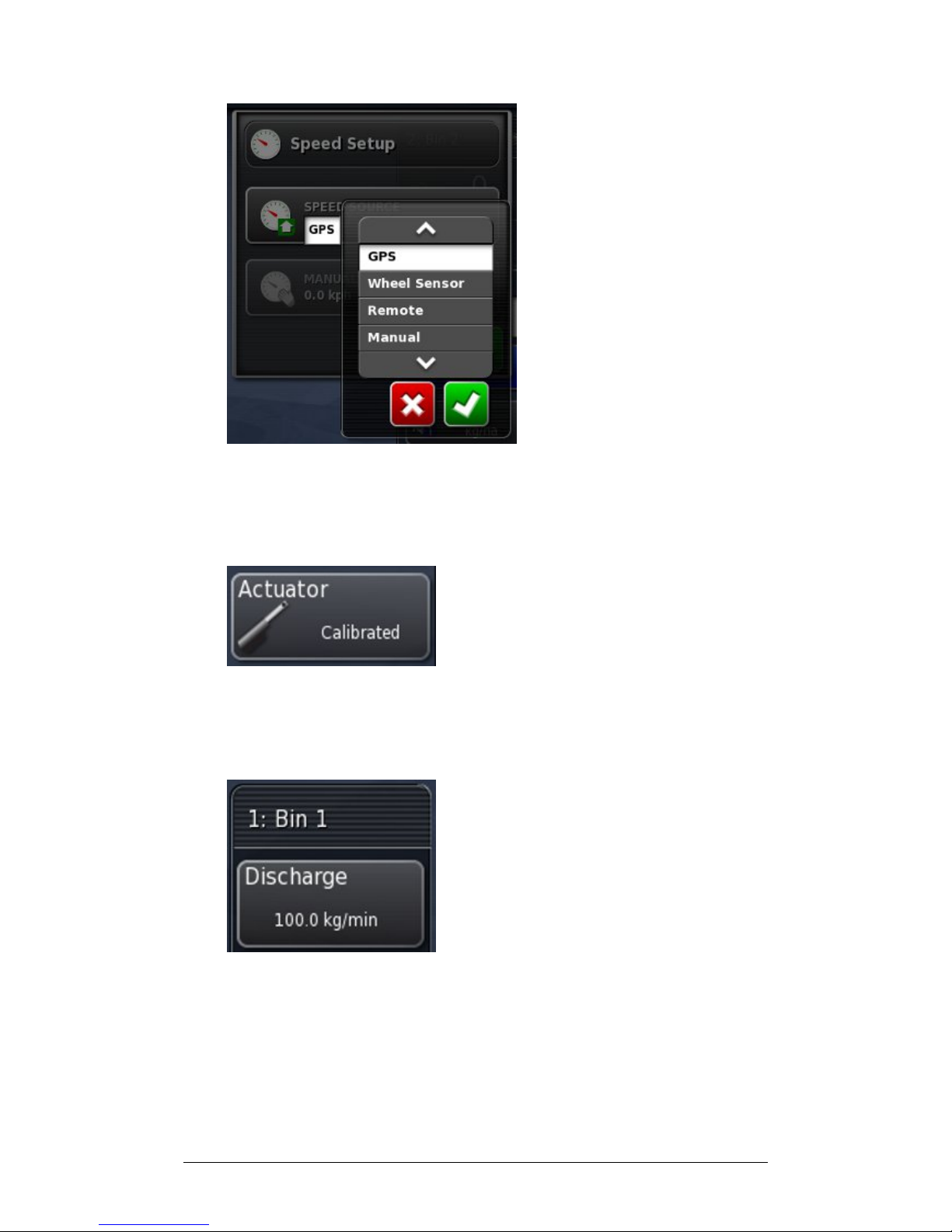
3. Choose the source and Confirm.
4. If Wheel Sensor has been chosen, select Wheel Sensor to
calibrate the wheel sensor. Follow the prompts.
5. If an Actuator is being used, select Actuator to calibrate
the actuator. This will align the open/close positions with
the sensor. Follow the prompts.
6. Select Discharge to calibrate the bin manually, to a
single point (actuator or belt driven) or multiple points
(actuator only). Choose the method of calibration and
follow the prompts.
Page 91
Chapter 4 - Operations 4.9 Managing the Spinners
X30 Spreader Controller
4-21
4.9 Managing the Spinners
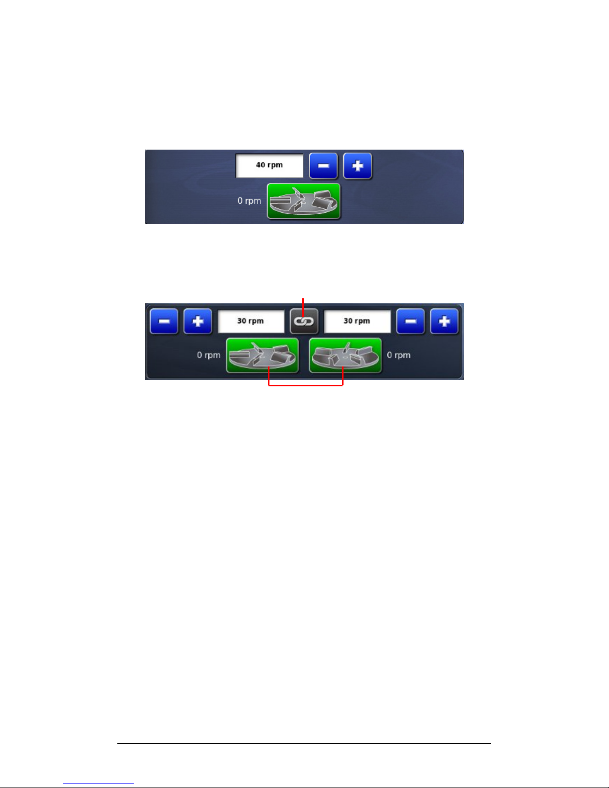
If only one spinner controller is setup, the following Spinner
Panel will appear.
If two spinners and controllers are set up the following
Spinner Panel will display.
Spinner Lock
Spinner On/Off Switches
1. Select the Spinner Lock to lock or separate spinner
speeds.
2. Select the Spinner On/Off Switches to turn spinners on
(green) and off (red) during operations. This switch will
turn spinners on / off even if the spinners have been set
to Track Master.
Page 92
Chapter 4 - Operations 4.10 Using the Master Switch
X30 Spreader Controller
4-22
4.10 Using the Master Switch
When Virtual Master has been chosen in the setup options,
the Spreader Master Switch turns the spreader system on
from the X30 Console.
This switch does not work if External ECU Sense was chosen
during setup.
The Master Switch button appears in green, white or red to
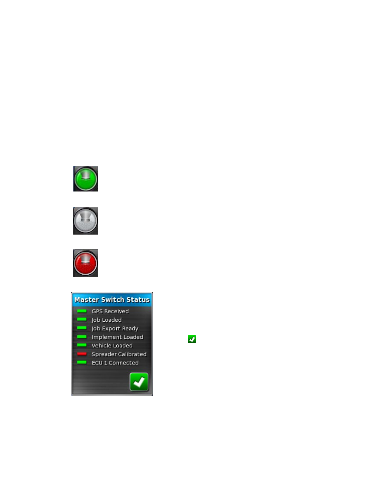
indicate the readiness of the system:
Green: Spreader Controller is on and working. Select
the master switch to turn the spreader off.
White: Spreader Controller is ready to use. Select the
master switch to turn the spreader on.
Red: Spreader Controller is off and cannot be used.
Select the Master Switch to see possible causes of the
problem. See the example below.
Green indicates that the system is ready.
Red indicates that the system is not
ready.
Select to return to the main screen
and complete the necessary action.
Page 93
Chapter 4 - Operations 4.11 Using Map Views and Layers
X30 Spreader Controller
4-23
4.11 Using Map Views and Layers
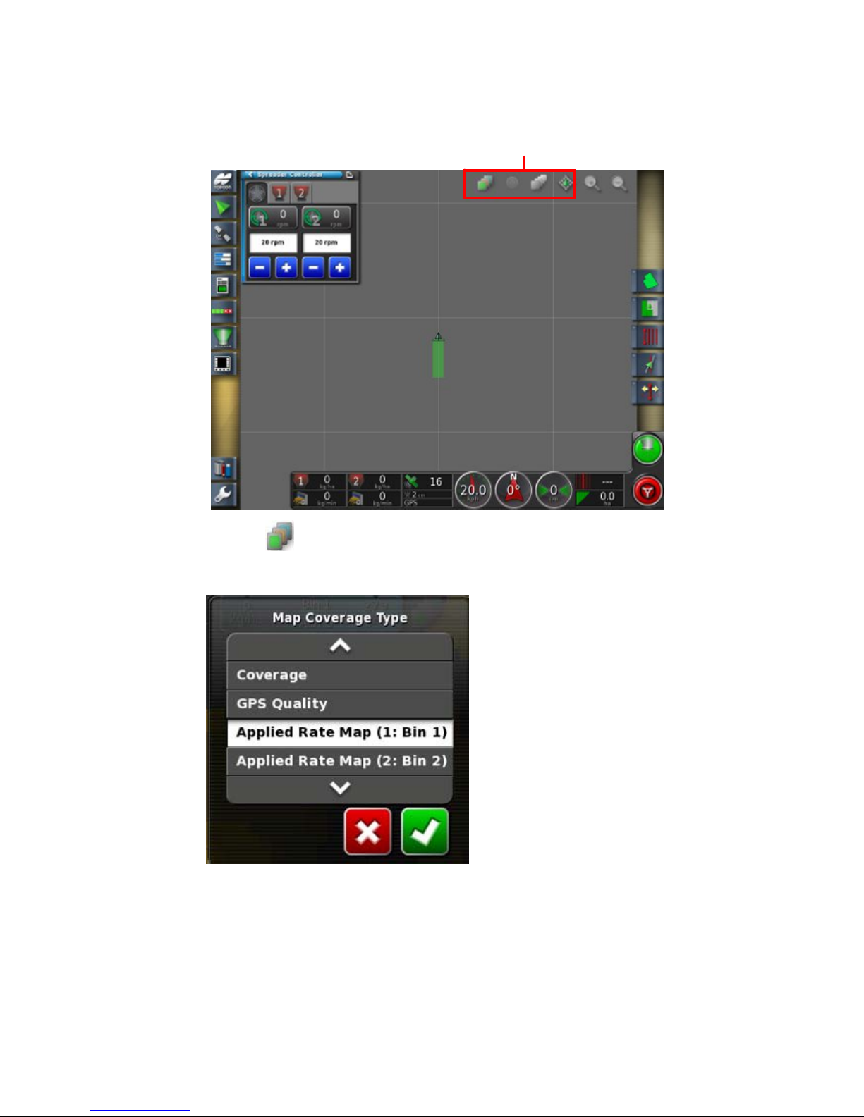
Map Layer and Map View Icons
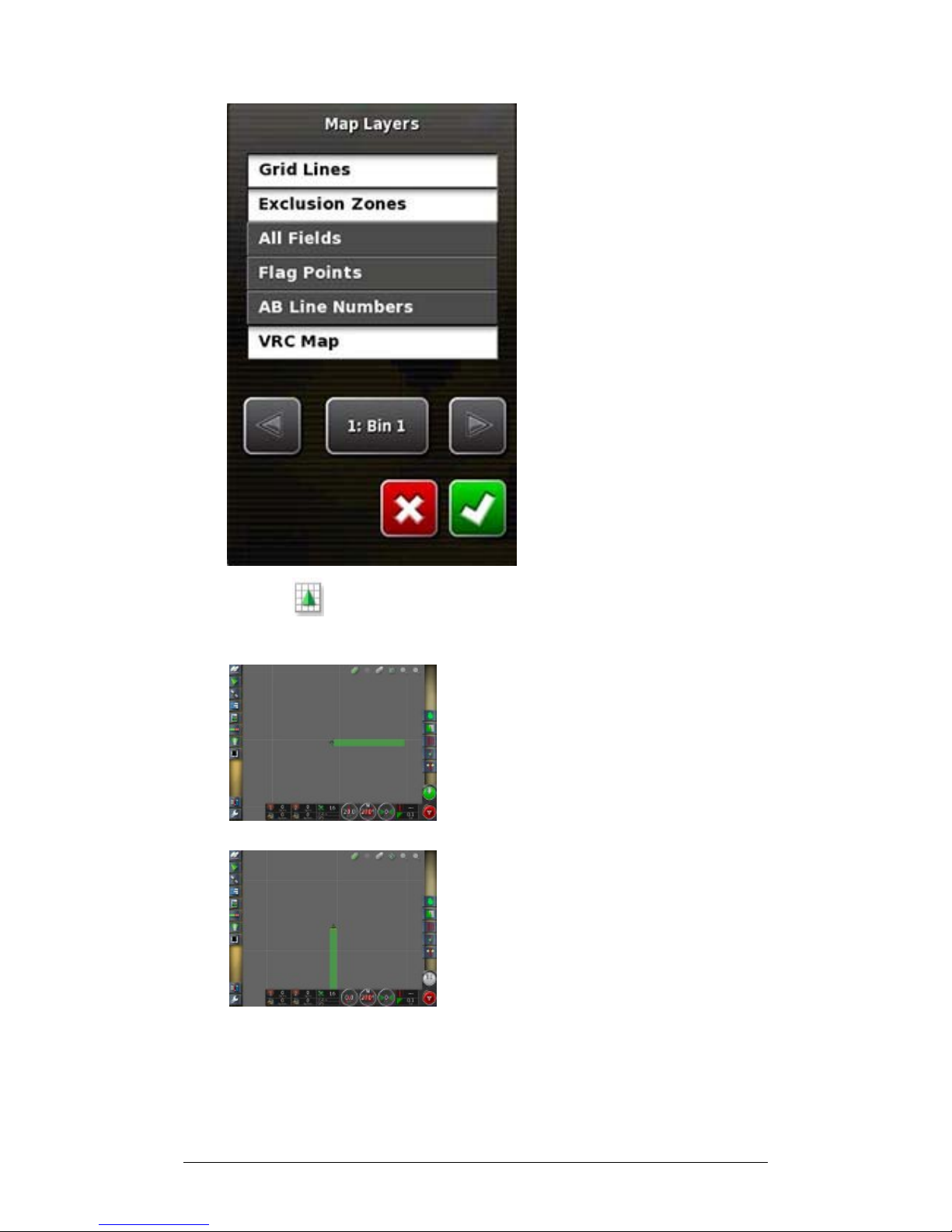
1. Select to choose which coverage will appear on the
screen.
Page 94
Chapter 4 - Operations 4.11 Using Map Views and Layers
X30 Spreader Controller
4-24
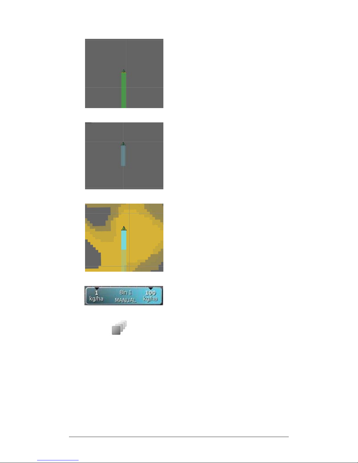
Coverage shows in Green
Application rate shows in Blue.
If working with Variable Rate
Control, variable application rate
shows in shades of Blue.
Legend displays for rate.
2. Select to choose which information layers will
appear. For more information on this refer to the Auto
Guidance and Auto Steering Manual.
Page 95
Chapter 4 - Operations 4.11 Using Map Views and Layers
X30 Spreader Controller
4-25
3. Select to toggle views the map (north up, heads up or
perspective)
North Up View places North at the
top of the screen.
Heads Up View places vehicle with
its current direction at the top of
the screen.
Page 96

Chapter 4 - Operations 4.11 Using Map Views and Layers
X30 Spreader Controller
4-26
Perspective View places map into
perspective with the implement at
bottom of screen.
Page 97

X30 Spreader Controller
5-1
Chapter 5 - Variable Rate Control
In order to use Variable Rate Control (VRC) on a job, the
VRC prescription map must be set up in the X30 Console.
Variable Rate Control must be enabled in setup. If this has
not been enabled, go to the Main Setup Menu, select System
and select Features to enable VRC.
Drive to the edge of the area to be worked before
downloading the map.
5.1 Loading VRC Map Files
5.2 Using Variable Rate Control
5.3 Downloading VRC Map Files with AgJunction
Page 98
Chapter 5 - Variable Rate Control 5.1 Loading VRC Map Files
X30 Spreader Controller
5-2
5.1 Loading VRC Map Files
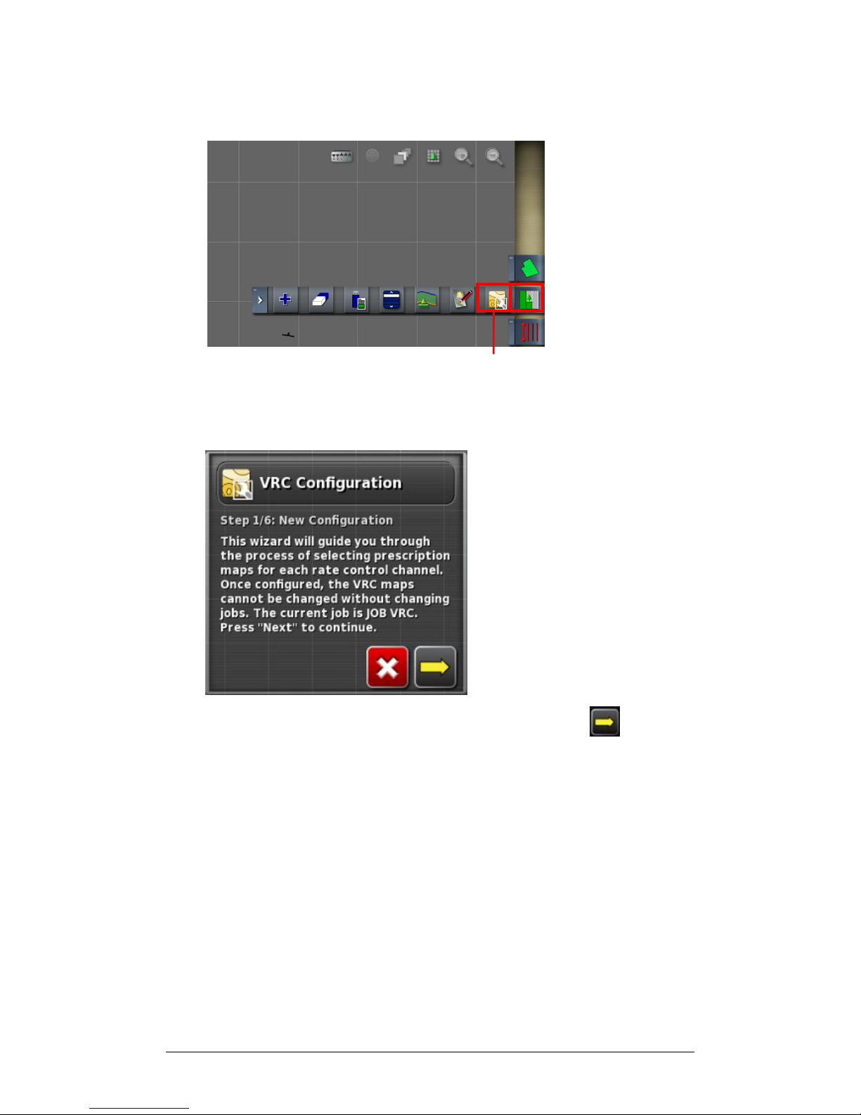
Configure VRC for this Job Icon
1. Select the Job Menu from the toolbar on the right of the
screen and select Configure VRC for this job.
2. Read the wizard instructions and select Next .
Page 99
Chapter 5 - Variable Rate Control 5.1 Loading VRC Map Files
X30 Spreader Controller
5-3
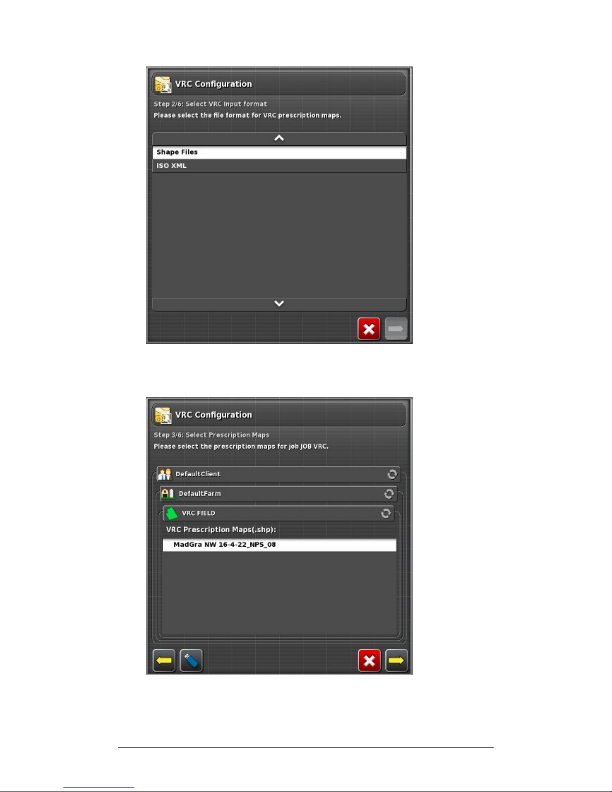
3. Select the file format of the VRC map file and select
Next.
4. Locate and choose the VRC map file and select Next.
Page 100
Chapter 5 - Variable Rate Control 5.1 Loading VRC Map Files
X30 Spreader Controller
5-4
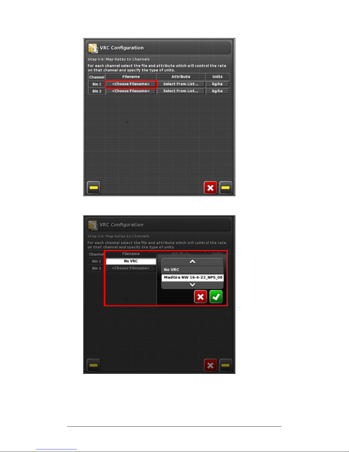
5. Select Choose File Name next to the channel for Bin 1.
6. Choose the file and Confirm.
 Loading...