

Page 1

X30
Console
YieldTrakk YM-1
Yield Monitoring
Operator’s Manual
www.topconpa.com
Page 2

Page 3

YieldTrakk YM-1
Yield Monitoring
Operator’s Manual
Part Number: 1006428-01-EN
Rev Number: 1.0
For use with Software Version 3.20
© Copyright Topcon Precision Agriculture
June 2015
All contents in this manual are copyrighted by Topcon. All rights reserved. The information
contained herein may not be used, accessed, copied, stored, displayed, sold, modified,
published or distributed, or otherwise reproduced without express written consent from
Topcon.
www.topconpa.com
Page 4

Page 5

Preface
This manual provides information about operating and maintaining this Topcon
Precision Agriculture product. Correct use and servicing is important for safe and
reliable operation of the product.
It is very important that you take the time to read this manual before using the product.
Information in this manual is current at the time of publication. A system may vary
slightly. The manufacturer reserves the right to redesign and change the system as
necessary without notification.
Terms and Conditions
Note: Please read these Terms and Conditions carefully.
General
APPLICATION - You accept these Terms and Conditions by purchasing the product from
Topcon Precision Agriculture (TPA) or from one of TPA’s product dealers.
COPYRIGHT - All information contained in this manual is the intellectual property of, and
copyrighted material of TPA. All rights are reserved. You may not use, access, copy, store,
display, create derivative works of, sell, modify, publish, distribute, or allow any third parties
access to, any graphics, content, information or data in this manual without TPA’s express
written consent and may only use such information for the care and operation of your product.
The information and data in this manual are a valuable asset of TPA and are developed by the
expenditure of considerable work, time and money, and are the result of original selection,
coordination and arrangement by TPA.
TRADEMARKS – ZYNX, PROSTEER, EAGLE, KEE Technologies, Topcon, Topcon
Positioning Systems and Topcon Precision Agriculture are trademarks or registered
trademarks of the Topcon Group of companies. Microsoft and Windows are trademarks or
registered trademarks in the United States and/or other countries of Microsoft Corporation.
Product and company names mentioned herein may be trademarks of their respective owners.
WEBSITE AND OTHER STATEMENTS - No statement contained at the website of TPA
or any other Topcon Group company or in any other advertisements or TPA literature or
made by an employee or independent contractor of TPA modifies these Terms and
Conditions.
IMPORTANT: SAFETY - Improper use of the product can lead to death or injury to
persons, damage to property and/or malfunction of the product. The product should only be
repaired by authorized TPA service centers. You should closely review the safety warnings
and directions as to the proper use of the product in this manual and at all times comply with
the same.
Limited Warranty
ELECTRONIC AND MECHANICAL COMPONENTS -TPA warrants that the electronic
components manufactured by TPA shall be free of defects in materials and workmanship for a
period of one year from the original date of shipment to the dealer. TPA warrants that all
valves, hoses, cables and mechanical parts manufactured by TPA shall be free of defects in
materials and workmanship for a period of 90 days from the date of purchase.
i
Page 6

RETURN AND REPAIR - During the respective warranty periods, any of the above items
found defective may be shipped to TPA for repair. TPA will promptly repair or replace the
defective item at no charge, and ship it back to you. You must pay the shipping and handling
charges in respect of the same. Calibration of components, labor and travel expenses incurred
for in-field removal and replacement of components are not covered in this warranty policy.
The foregoing warranty shall NOT apply to damage or defects resulting from:
(i) disaster, accident or abuse
(ii) normal wear and tear
(iii) improper use and/or maintenance
(iv) unauthorized modifications of the product; and/or
(v) use of the product in combination with other products not supplied or specified by TPA.
Software accompanying any product is licensed for use in connection with the product and
not sold. Use of software that is provided with a separate end user license agreement
(“EULA”) will be subject to the terms and conditions, including those relating to limited
warranty, of the applicable EULA, notwithstanding anything in these Terms and Conditions
to the contrary.
WARRANTY DISCLAIMER - OTHER THAN FOR THE ABOVE WARRANTIES,
WARRANTIES PROVIDED IN AN APPLICABLE WARRANTY CARD, APPENDIX
OR END USER LICENSE AGREEMENT, THIS MANUAL, THE PRODUCT AND
RELATED SOFTWARE ARE PROVIDE ‘AS-IS’. THERE ARE NO OTHER
WARRANTIES AND TO THE EXTENT ALLOWED BY LAW TPA EXCLUDES ALL
IMPLIED TERMS, CONDITIONS AND WARRANTIES IN RESPECT OF THE
MANUAL AND THE PRODUCT (INCLUDING ANY IMPLIED WARRANTY OR
MERCHANTABILITY OR FITNESS FOR ANY PARTICULAR USE OR PURPOSE).
TPA IS NOT RESPONSIBLE FOR THE OPERATION OF GNSS SATELLITES
AND/OR AVAILABILITY, CONTINUITY, ACCURACY, OR INTEGRITY OF GNSS
SATELLITE SIGNALS.
LIABILITY LIMIT AND INDEMNITY - TPA and its dealers, agents and representatives
shall not be liable for technical or editorial errors or omissions contained herein or for special,
indirect, economic, incidental or consequential damages resulting from the furnishing,
performance or use of this material, the product or its accompanying software (including
where TPA has been advised of the possibility of such damage). Such disclaimed damages
include but are not limited to loss of time, loss or destruction of data, loss of profit, savings or
revenue or loss of or damage to the product. You shall defend, indemnify and hold TPA
harmless from and against any claims, actions, suits, damages, losses, liabilities and costs
(including attorneys’ fees) arising from, or relating to (a) your operation use, or maintenance
of the product and/or software other than as provided for in this manual or the applicable end
user license agreement; and (b) your negligence or wrongful act or omission in respect of the
product.
In any event, TPA’s liability to you or any other person for any claim, loss or damage (in
contract, tort or on any other basis) will be limited (in TPA’s option) to either (a) the
replacement or repair of the product, or (b) payment of the cost of replacing or repairing the
product.
Other
These Terms and Conditions may be amended, modified, superseded or cancelled, at any time
by TPA. These Terms and Conditions will be governed by, and construed in accordance with:
ii
Page 7
FCC Compliance Statement (USA)
FCC Compliance Statement (Canada)
CE Statement (European Community)
- the laws of South Australia if the product is sold and supplied to you in Australia (in
which case the courts of South Australia or the Federal Court of Australia (Adelaide
Registry) have exclusive jurisdiction in respect of any claim or dispute) or
- the laws of the State of California if the product is sold and supplied to you outside of
Australia
- the provisions of the United Nations Convention on Contracts for the International Sale of
Goods shall not apply to these Terms and Conditions.
All information, illustrations, and applications contained herein are based on the latest
available information at the time of publication. TPA reserves the right to make product
changes at any time without notice.
If any part of these Terms and Conditions would be unenforceable, the provision must be read
down to the extent necessary to avoid that result, and if the provision cannot be read down to
that extent, it must be severed without affecting the validity and enforceability of the
remainder of these Terms and Conditions.
Service Information
Service assistance can be provided by contacting your local TPA Authorized Dealer.
Communications Regulation Informati on
This equipment has been tested and found to comply with the limits for a
Class ‘A’ digital device, pursuant to Part 15 of the FCC Rules. Operation
of this equipment in a residential area is likely to cause harmful
interference in which case the user will be required to correct the
interference at the user's expense.
This Class A digital apparatus meets all requirements of the Canadian
Interference-Causing Equipment Regulation.
Warning: This is a class ‘A’ product. In a domestic environment this
product may cause radio interference in which case the user may be
required to take adequate measures.
RCM Statement (Australia & New Zealand)
This product meets the applicable requirements of the Australia and New
Zealand EMC Framework.
Type Approval and Safety Regulati ons
Type approval may be required in some countries to license the use of transmitters on
certain band frequencies. Check with local authorities and your dealer. Unauthorized
modification of the equipment may void that approval, the warranty and the license to
use the equipment.
iii
Page 8

The receiver contains an internal radio-modem. This can potentially send signals.
Regulations vary between countries, so check with the dealer and local regulators for
information on licensed and unlicensed frequencies. Some may involve subscriptions.
Radio and Television Interf erence
This computer equipment generates, uses, and can radiate radio-frequency energy. If it
is not installed and used correctly in strict accordance with TOPCON Precision
Agriculture instructions, it may cause interference with radio communication.
You can check if interference is being caused by this equipment by turning the Topcon
equipment off to see if the interference stops. If the equipment is causing interference
to a radio or other electronic device, try:
• Turning the radio antenna until the interference stops
• Moving the equipment to either side of the radio or other electronic device
• Moving the equipment farther away from the radio or other electronic device
• Connecting the equipment to another circuit that is not linked to the radio.
To reduce potential interference operate the equipment at the lowest gain level that
will allow successful communication.
If necessary contact your nearest Topcon Precision Agriculture dealer for assistance.
Note: Changes or modifications to this product not authorized by TOPCON Precision
Agriculture could void the EMC compliance and negate authority to operate the
product.
This product was tested for EMC compliance using Topcon Precision Agriculture
peripheral devices, shielded cables and connectors. It is important to use Topcon
Precision Agriculture devices between system components to reduce the possibility of
interference with other devices
General Safety
DANGER: It is essential that the following information and the product
specific safety information is read and understood.
Most incidents arising during operation, maintenance and repair are caused by a failure
to observe basic safety rules or precautions. Always be alert to potential hazards and
hazardous situations.
Always follow the instructions that accompany a Warning or Caution. The information
these provide aims to minimize risk of injury and/or damage to property.
In particular follow instructions presented as Safety Messages.
iv
Page 9

DANGER: Indicates an imminently hazardous situation that, if not
WARNING: Indicates a potentially hazardous situation that, if not
CAUTION: Indicates a potentially hazardous situation that, if not
WARNING: DO NOT remove or obscure safety signs. Replace any
Safety Messages and Warnings
The safety symbol is used with the relevant word: DANGER, WARNING or
CAUTION.
Messages marked in this way recommend safety precautions and practices. LEARN
and apply them.
avoided, could result in DEATH OR VERY SERIOUS INJURY.
avoided, could result in DEATH OR SERIOUS INJURY.
avoided, may result in MINOR INJURY.
Safety Signs
safety signs that are not readable or are missing. Replacement signs
are available from your dealer in the event of loss or damage.
If a used vehicle has been purchased, make sure all safety signs are in the correct
location and can be read. Replace any safety signs that cannot be read or are missing.
Replacement safety signs are available from your dealer.
Operator Safety
WARNING: It is YOUR responsibility to read and understand the
safety sections in this book before operating this vehicle. Remember
that YOU are the key to safety.
Good safety practices not only protect you, but also the people around you. Study this
manual as part of your safety program. This safety information only relates to Topcon
equipment and does not replace other usual safe work practices.
WARNING: Ensure power is removed from the Topcon equipment
prior to maintenance or repair of the vehicle or implements.
WARNING: Ensure appropriate precautions are taken prior to
handling any hazardous substances. Always read the Material Safety
Data Sheet prior to commencing work.
v
Page 10
WARNING: In some of the illustrations or photos used in this
WARNING: Topcon is committed to good environmental
manual, panels or guards may have been removed for demonstration
purposes. Never operate the vehicle with any panels or guards
removed. If the removal of panels or guards is necessary to make a
repair, these MUST be replaced before operation.
WARNING: Always check that any suspended vehicle attachments
are lowered to the ground before beginning repair or maintenance
work on a vehicle.
WARNING: Vehicle and implement parts can become hot during
operation and may be under pressure. Refer to vehicle manuals.
WARNING: Wear appropriate protective clothing for the task being
undertaken and conditions.
WARNING: Do not operate equipment around explosive equipment
or supplies.
performance and minimizes the use of any potentially harmful
substances in its products. However, it is always advisable not to
handle damaged electronic equipment.
This Topcon product may contain a sealed lithium battery.
Always dispose of any electronic equipment thoughtfully and
responsibly.
Exposure to Radio Frequency
Exposure to energy from radio frequencies is an important safety issue. Keep a
distance of at least 20 cm (7.8 inches) between people and any radiating antenna. Keep
a distance of at least 20 cm between transmitting antennas.
WARNING: Products using cellular modem or an RTK base station
can transmit radio frequency energy. Check with your dealer.
This device is designed to operate with TPA approved antennas. Discuss with your
dealer.
Preparation for Operation
• Read and understand this manual and learn all of the controls before you use the
equipment.
• Keep the manual with the equipment.
• If the equipment is moved to another vehicle, move the manual as well.
vi
Page 11

• Read the manual for the vehicle with which the equipment will be used and
check that the vehicle has the correct equipment required by local regulations.
• Make sure you understand the speed, brakes, steering, stability, and load
characteristics of the vehicle before you start.
• Check all controls in an area clear of people and obstacles before starting work.
• Identify possible hazards.
WARNING: Topcon equipment must not be used by an operator
affected by alcohol or drugs. Seek medical advice if using prescription
or over-the-counter medication.
Disclaimer
Topcon accepts no responsibility or liability for damages to property, personal injuries,
or death resulting from the misuse or abuse of any of its products.
Further, Topcon accepts no responsibility for the use of Topcon equipment or the
GNSS signal for any purpose other than the intended purpose.
Topcon cannot guarantee the accuracy, integrity, continuity, or availability of the
GNSS signal.
The operator must ensure that the equipment is correctly turned off when not in use.
Before operating any vehicle equipped with Topcon products, read and understand the
following product specific safety precautions.
Important Safety Information
Operator Alertness and Respons ibilit y
The console helps the operator to steer the vehicle, but the operator remains in charge
and must be alert and in complete control of the vehicle at all times. The operator is
ultimately responsible for safe operation of this equipment.
It is essential that safety requirements are met when operating the console and any of
its components. All operators and other relevant personnel must be advised of safety
requirements.
Electrical Safety
WARNING: Incorrectly connected power can cause severe injury and
damage to people or the equipment.
When working with electrical components, you must do the following:
• Make sure the negative terminal of the battery is disconnected before doing any
welding on the vehicle.
• Check that all power cables to system components are connected to the correct
polarity as marked. Please refer to the vehicle manual for safety information.
vii
Page 12

WARNING: Ensure the steering switch is Off to prevent unintentional
• Check that equipment is grounded in accordance with installation instructions.
Operation and Risk of Obstacles
The following list is not exhaustive or limited. To use the console for assisted steering
along a defined wayline, the operator must ensure that it is used:
• Away from people and obstacles
• Away from high voltage power lines or other overhead obstructions (identify any
clearance problems before activating the console)
• On private property without public access
• Within cleared fields
• Off public roads or access ways.
Note that:
• The operator needs to know the vehicle’s position and the field conditions at all
times.
• The operator will need to respond if the GNSS satellite or differential correction
signal is lost momentarily.
• The console cannot detect obstacles (people, livestock or other).
• Only use the console in areas that are clear of obstacles and keep a proper
distance.
• Steering needs to be disengaged for manual control if an obstacle appears in the
path or the vehicle moves away from the wayline.
On/Off and Manual Control
engagement of the assisted steering. When repairing or maintaining
the vehicle/implement, ensure the vehicle CANNOT be moved.
Disengage steering, apply brakes and remove keys.
The operator must ensure that the steering switch is Off (all LED indicators are off)
when assisted steering is not being used.
The operator must disengage assisted steering and use manual control if an obstacle is
in the line of travel or moves into the line of travel, or if the vehicle steers away from
the desired wayline.
To disengage assisted steering:
• Turn the steering wheel a few degrees OR
• Select the Disengage Auto Steering button on the console AND/OR
• If using an external steering switch, disengage using the switch if the above
actions do not disengage assisted steering.
viii
Page 13

WARNING: A warning signal appears on safety signs and in this
Vehicle Shut Down Safety
Before leaving the vehicle, disengage assisted steering, disengage external steering
switch if this is being used, and remove the key from the key switch.
Using a Reference (Base) Station
WARNING: Do not move a reference station while in operation.
Moving an operating reference station can interfere with the
controlled steering of a system using the reference station. This could
result in personal injury or damage to property.
Operators and other affected personnel must be advised of the following safety
precautions.
• Do not erect the reference station under or within the vicinity of high voltage
power lines.
• When using the portable reference station, make sure that the tripod is securely
mounted.
To Get the Best Out of the Product
Back up data regularly. The console has large, but limited storage capacity. Use the
Diagnostics Mini-view to view capacity available. A warning screen displays if
storage is reaching its limit.
Be aware of file format compatibility. Discuss compatible formats with the dealer.
Topcon Agricultural Products are hardy and designed to work in tough conditions.
However, if equipment is unused for a length of time, store away from water and
direct heat sources.
Alert Symbols
In this manual two alert symbols are used:
Note: This offers additional information.
manual to show that this information is very important to your safety.
LEARN these and APPLY them.
ix
Page 14

Table of Contents
Introduction ............................................................... 1
Enabling Yield Monitoring ........................................ 3
Enabling ISOBUS ...................................................... 7
Setting up a New Impleme nt ................................... 11
4.1. Setting the implement geometry .......................................... 15
4.2. Setting up the master switch ............................................... 17
4.3. Setting up the harvester ...................................................... 18
Console Controls .................................................... 19
5.1. Using the master switch ...................................................... 19
5.2. Using the yield monitor dashboard ...................................... 21
5.3. Opening the yield monitor mini-view .................................... 22
5.3.1. Harvest cur rent .............................................................. 23
5.3.2. Job totals ....................................................................... 26
5.3.3. Sub totals ...................................................................... 27
5.4. Viewing map layers ............................................................. 28
5.4.1. Editing the legends ........................................................ 29
YieldTrakk Operation .............................................. 31
6.1. Getting the best results ........................................................ 31
6.2. Operation ch eck l is t .............................................................. 31
UT Screens ............................................................... 33
7.1. Opening the YieldTrakk UT window .................................... 33
7.2. Units displayed .................................................................... 34
7.3. Main screen ......................................................................... 35
7.4. Totals screen ....................................................................... 37
7.5. Crop settings screen ............................................................ 38
7.5.1. Header setup screen ..................................................... 40
x
7.5.2. Calibrati o n cor r e ction screen ........................................ 42
7.6. Set tare scree n .................................................................... 43
7.7. Technician sc ree n ............................................................... 44
7.7.1. Header cut out se nsor ................................................... 45
7.7.2. Combine sel ect ............................................................. 46
7.7.3. Product edit ................................................................... 46
7.7.4. Speed sens or ................................................................ 47
7.7.5. Yield sensor .................................................................. 47
Page 15

7.7.6. Moisture se nso r ............................................................. 49
7.7.7. Inclinometer .................................................................. 51
7.8. Factory setup screen ........................................................... 53
Exporting Data ......................................................... 55
Upgrading ECU Firmware ....................................... 57
xi
Page 16

xii
Page 17

Introduction
The YieldTrakk yield monitor is a console device that captures sensor
data from a harvesting machine, combines that sensor data with
geodetic data, and logs that information to its file system in real time.
Simultaneously, the yield monitor displays this geodetic yield data in
various formats to the end user.
A typical yield monitor system consists of:
• A mass flow sensor (most common form is an impact type plate)
• A grain moisture sensor
• A GPS receiver
• A console
1
Page 18

2
Page 19
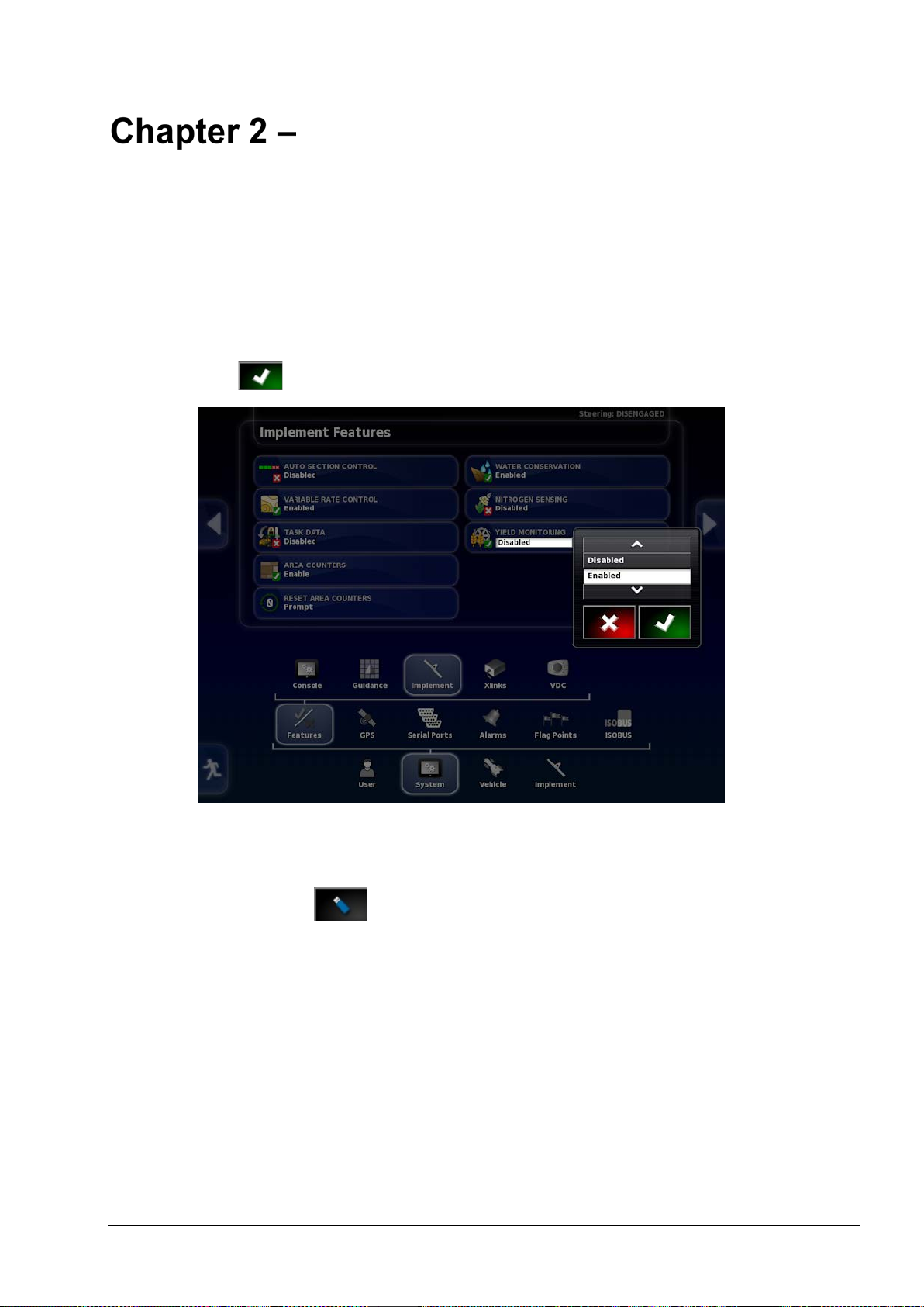
Enabling Yield Monitoring
Note: When the Yield Monitoring software is purchased, a
registration code is supplied. This code is required to enable Yield
Monitoring functionality.
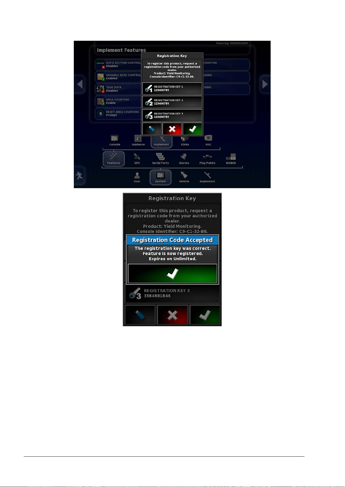
1. Select System / Features / Implement.
2. Select YIELD MONITORING and select Enabled, then
confirm .
3. Select REGISTRATION KEY 1.
Alternatively, if the registration code is supplied on a USB, select
the USB button and follow the displayed wizard.
3
Page 20
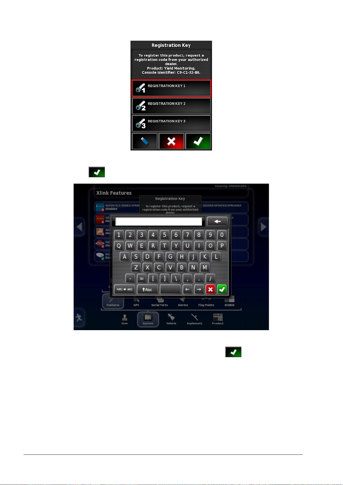
4. Enter the first set of numbers in the supplied registration code and
confirm .
5. Select REGISTRATION KEY 2, enter the second set of
numbers in the registration code and confirm .
4
Page 21
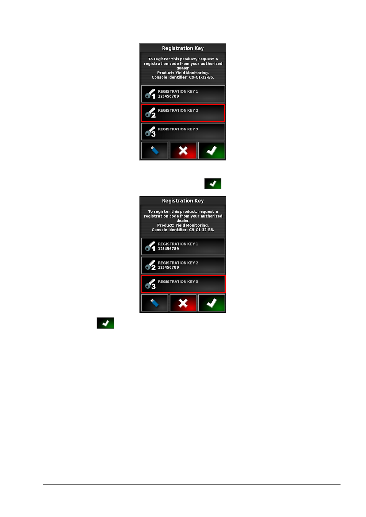
Chapter 2 – Enabling Yield Monitoring
6. Select REGISTRATION KEY 3, enter the third set of numbers
in the registration code and confirm .
7. Confirm the registration.
5
Page 22
6
Page 23
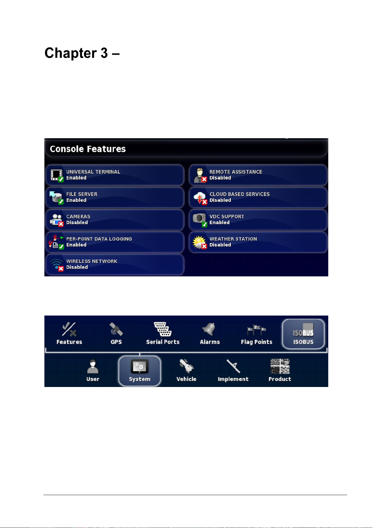
Enabling ISOBUS
Enables the ISOBUS Universal Terminal server that allows interaction
with the YieldTrakk ISOBUS compliant ECU.
To enable ISOBUS / Universal Terminal:
1. Select System / Features / Console.
2. Select UNIVERSAL TERMINAL and select Enabled.
3. Select System / ISOBUS / UT.
The Universal Terminal setup page is displayed.
7
Page 24

• Universal terminal: Controls whether the UT server is actively
receiving connections from other devices.
This may be useful if there are multiple UTs on the bus and
multiple UTs claim to be the primary UT (in which case the UT
will go offline automatically and require the UT Number to be
changed before it will go online again), or to temporarily
deactivate the UT on the console.
• UT number: Sets the UT number for the console. If there are
multiple UTs on the bus, use this setting to assign a unique
number to this UT to avoid conflicts. The UT with number 1 will
be the default UT. If the UT client doesn’t appear on the correct
UT you may need to reconfigure its UT number appropriately. If
there is a conflict, the following message will appear:
'The UT Number of this UT conflicts with another UT on the bus,
and this UT has been disabled. Please make sure that this UT has
a unique UT Number.'
• Soft keys per column: Sets the number of available softkeys on
the UT interface on the Operation screen. Note: This should be
set to 6.
• Soft key location: Sets the location of the softkeys on the UT
interface and the number of columns (1 or 2).
8
Page 25

Chapter 3 – Enabling ISOBUS
• Working set key location: Sets the visibility and location of the
keys that switch the interface between ECUs (if more than one
ISOBUS compliant ECU is connected). Note: This should be set
to Hidden.
Note: Ensure that ISO GROUND SPEED and GPS NMEA2000 are
both enabled. These are accessed via the Implement / Speed menu.
9
Page 26

10
Page 27

Setting up a New Implement
Once the yield monitoring functionality is enabled, the connected
implement must be set up in the console. Auto section control is
automatically enabled to allow auto cut width to work.
1. Select Implement / New / Custom.
2. Use the arrows to choose the type. Type can be Rigid, Pivoted
(Tow behind), Front , or Double Pivoted (Tow between).
Note: Front would usually be selected.
3. The system will warn you that it needs to restart after you have
finished setting up the implement. Select to continue (or
select to cancel the action).
11
Page 28

4. Select IMPLEMENT NAME if you wish to change the default
name of the implement.
5. Enter the preferred name and confirm .
6. Confirm the new implement details to continue.
The ECU setup wizard starts. The wizard contents are dependent
on the selections made.
Note: If you make a mistake in the wizard, it is possible to go
12
back and change a selection.
Page 29

Chapter 4 – Setting up a New Implement
7. Select IMPLEMENT CONTROL.
8. Select Yield Monitor, confirm and select next .
9. Select YIELD MONITOR.
10. Select the required yield monitor (YieldTrakk – YM-1) and
select next .
11. When the screen shows that the setup is complete, confirm .
The console will restart.
13
Page 30

12. Ensure the implement setup is complete and correct. Refer to
Implement Setup in the X30 Guidance and Auto Steering
Operator Manual for instructions.
14
Page 31

Chapter 4 – Setting up a New Implement
4.1. Setting the implement geometry
Sets the implement measurements so that guidance can work
accurately.
Note: Measure the implement dimensions as accurately as possible.
The recommended tolerance is +/- 5 cm.
When an ISOBUS implement is connected, some of the geometry
items are provided by the implement and cannot be altered in the X30.
Any changes to these must be made in the implement ISOBUS UT
control screen.
To set the implement geometry:
1. Select Implement / Geometry.
2. Select an implement dimension. The name of the dimension
appears in the title bar.
Dimensions requested vary according to the type of implement
selected.
3. Add or adjust dimensions where needed and confirm.
15
Page 32

Measurements used are as follows:
• Swath Width: Measures the working width of the implement
(that is, the width of the area that is treated during one pass of the
implement).
• Working Length: Length from the start to the finish of the
working area of the boom. Together with swath width, it defines
the ‘Working Area’, which is the region that product is applied
over for that boom.
• Overlap: Measures the width of the overlap between two
adjacent passes.
• Implement Offset: Measures the distance between the hitch point
and the wheels of the implement.
• Implement Wheels Offset: Measures the distance between the
wheels and the working area of the implement.
• Inline Offset: Measures the off-center offset of the implement
relative to the hitch point. Enter a positive number if the
implement is shifted to the right and a negative number if it is
shifted to the left.
• Trailer Offset: Measures the distance between the trailer hitch
point and the trailer wheels.
• Trailer Wheels Offset: Measures the distance between the
implement hitch point and the trailer wheels.
16
Page 33

Chapter 4 – Setting up a New Implement
4.2. Setting up the master switch
The master switch turns on the application control and also enables
the coverage map on the guidance screen.
To set up the master switch:
1. Select Implement / Master Switch.
Virtual
Enables the master switch to be operated by selecting the virtual
master switch on the console Operation screen.
Follows device work state
Follows the state of the YieldTrakk ISOBUS ECU. The virtual master
switch is then for status display only.
17
Page 34

4.3. Setting up the harvester
1. Select Implement / Harvester / Bin.
• Capacity: The volume of the combine bin.
2. Select Implement / Harvester / ISOBUS Settings.
• Low speed shutoff: Sets the speed at which the master switch
will disengage. If it is set to 0.0 kph, the feature is off.
18
Page 35

Green indicates that the system is ready.
Console Controls
5.1. Using the master switch
When Virtual has been selected in the Setup screen (Implement /
Master Switch), the harvester master switch on the Operation screen
turns the harvester system on. This switch does not work if Follows
device work state is selected as the master switch.
The switch also indicates the readiness of the system:
Red
Harvester controller is off and cannot be used. Select the master
switch to see possible causes of the problem. See example below.
Green
Harvester controller is on and working. Select the master switch to
turn the harvester off.
White
Harvester Controller is ready to use. Select the master switch to turn
the harvester on.
Red indicates that the system is not
ready.
Note: When the master switch is turned off during harvesting, the
master switch flashes yellow and a countdown is displayed. This
Select to return to the main
screen and complete the necessary
action.
19
Page 36

indicates that task shut down is delayed so that the final crop
harvested has time to pass the yield sensors before the task is stopped.
20
Page 37

Chapter 5 – Console Controls
5.2. Using the yield monitor dashboard
Yield monitor information is added to t he dashboard when the
harvester controller is enabled.
1. Select anywhere on the dashboard to customize the information it
displays.
2. Press again on the particular panel to be customized and further
options display.
3. Deselect and select options as required.
4. Confirm the new dashboard display. The selected options appear
on the dashboard.
21
Page 38

5.3. Opening the yield monitor mini-view
The yield monitor controller appears in a mini-view accessed via the
navigation bar on the left side of the operation screen.
Note: The figures displayed in the mini-views may also be shown via
the YieldTrakk UT screens. See page 33.
1. Select the Yield Monitor Controller to open a mini-view .
Use the mini-view to monitor yield data for current harvest, job totals
and sub-totals.
The information displayed may be customised.
2. Press the information area of the mini-view to display the options
available.
3. Deselect and select options as required.
22
Page 39

Chapter 5 – Console Controls
5.3.1. Harvest current
1. Press the information area of the mini-view to display the options
available.
• Current wet yield: T/Ha (Bu/Ac) based on the raw yield
data.
• Current dry yield: Calculated T/Ha (Bu/Ac) based on
current wet yield data with respect to the desired moisture
reference point (i.e. after it has dried). The moisture reference
point is set via the YieldTrakk UT interface.
• Current wet productivity: T/Hr (Bu/Hr) Raw yield sensor
data.
23
Page 40

• Current dry productivity: Calculated T/Hr (Bu/Hr) based
on the current wet productivity with respect to the desired
moisture reference point. The moisture reference point is set
via the YieldTrakk UT interface.
• Current moisture content: Percentage raw moisture sensor
data.
• Wet harvested amount: Raw Total Tonnes (Bu) harvested.
• Dry harvested amount: Calculated Total Tonnes (Bu) based
on the wet harvested amount with respect to the desired
moisture reference point. The moisture reference point is set
via the YieldTrakk UT interface.
• Working width: In metres (inches) measuring how much of
the combine's header is actually harvesting (uses auto-cutwidth from existing coverage to vary this).
• Current cut rate: Ha/Hr (Bu/Hr) based on speed and
working width. Sometimes used as a measurement of
productivity.
2. Deselect and select options as required.
Product configuration
The Product Configuration button displays the Yield window.
This window selects the product being harvested and internally maps
it to the rate channels.
24
Page 41

Chapter 5 – Console Controls
1. Select PRODUCT NAME to select a product from the list, or to
add a new product.
Selecting New Product opens the New Product Setup wizard.
Follow the wizard to add a new product. Custom Product may be
selected to create a new product from scratch, or a product template
may be selected from the list.
Note: The product rate settings defined below are not relevant for
yield monitoring.
• Product rate increment: Defines how much the application rate
will change when the operator presses the application rate
up/down button. The rate can be changed by a fixed rate or by a
percentage of the rate set for Product rate preset 1. To change
the rate increment type:
25
Page 42

1. On the Setup screen, select User / Region / Units. The
APPLICATION RATE INCREMENT TYPE may be set to
Fixed rate or Percentage of Preset 1.
• Rate preset 1 / Rate preset 2: Defines preset application rates.
5.3.2. Job totals
The totals displayed on this mini-view are reset when a new job is
started.
1. Press the information area of the mini-view to display the options
available.
2. Deselect and select options as required.
26
Page 43

Chapter 5 – Console Controls
5.3.3. Sub totals
Sub totals are independently re-settable subtotals, typically reset when
the bin is emptied to keep track of the total per bin load (for example;
harvested amount and moisture content).
This could also be used to keep track of harvest subtotals per truck.
The Reset task window button opens a confirmation screen to
clear the data stored for the currently selected sub totals.
1. Press the information area of the mini-view to display the options
available.
2. Deselect and select options as required.
27
Page 44

5.4. Viewing map layers
The coverage map selector enables one type of coverage map to be
selected.
1. Select the highlighted icon to choose which coverage and
information layer will appear on the screen.
2. Press the center button and select from the list or press the
left/right arrows to scroll through the list with a live preview of
that layer in the map in the background.
• Coverage (Combine): Shows the area covered by the harvester.
• Coverage (Yield): Shows the area covered by the harvester with
a delay value equal to the time taken for the crop to get from the
header to the yield sensor. Refer to the Delay Time figure in
Yield sensor, page 47.
• Applied rate map (wet yield): T/Ha (Bu/Ac) based on the raw
yield data.
28
Page 45

Chapter 5 – Console Controls
• Applied rate map (dry yield): Calculated T/Ha (Bu/Ac) based
on current wet yield data with respect to the desired moisture
reference point (i.e. after it has dried).
• Applied rate map (moisture): Percentage raw moisture sensor
data.
• Applied rate map (raw yield): Reports exactly what the yield
sensor is measuring at that point in time in T/Hr. Sometimes
referred to as productivity.
• Applied rate map (cut rate): Ha/Hr (Bu/Hr) based on speed and
working width. Sometimes used as a measurement of
productivity.
Coverage shows in green.
Applied rate shows in selectable colors.
Legend displays for applied rates.
5.4.1. Editing the legends
The legends that are displayed for Applied Rate may be edited.
1. Click on the legend to display the legend color and range map.
29
Page 46

2. Select Edit to change the colors and ranges used.
30
Page 47

YieldTrakk Operation
6.1. Getting t h e b est results
To achieve the best possible accuracy, the system must be properly set
up and maintained. The main points to observe are:
• If harvesting particularly oily crops, check that the grain sensor
lenses and the moisture sensor fin stay reasonably clean.
• Cross-check moisture readings and grain density settings by
measuring reference samples of the crop at the start.
• Check and if required tare (zero) the yield reading with the
harvester running empty.
• The clean grain elevator chain should be in good condition and
correctly tensioned.
6.2. Operation checklist
Step When / why? How?
Check tare At least once per day,
or more often with
dirty or oily crops.
Set crop type Whenever a different
crop type is
harvested.
Check storage
moisture percentage
If incorrect, DRY
weight totals will be
incorrect.
See Set tare screen,
page 43.
See Crop settings
screen, page 38.
See Crop settings
screen, page 38.
Harvest a short strip For initial calibration
of crop moisture and
density.
31
Page 48

Step When / why? How?
Test moisture
percentage and adjust
Test crop density and
adjust (kg/hl)
Compare actual
At regular intervals
throughout the day .
Adjustment is needed
if the harvest moisture
reading is different
from that of a
reference moisture
meter.
At regular intervals
throughout the day .
An incorrect density
setting is one of the
most likely causes of
inaccurate yield data.
Adjustment may be
See Crop settings
screen, page 38.
A grain weight tester
is supplied with the
system. This is used
to determine the value
to enter on the Main
screen, see page 35.
See Crop settings
weight with
calculated weight
required if
YieldTrakk provides
consistent
discrepancies between
its yield readings and
the weighbridge
readings.
Note: Always check
moisture % and crop
density before
adjusting Crop Cal .
Factor.
screen, page 38.
32
Page 49

UT Screens
7.1. Opening the YieldTra kk UT window
To view the YieldTrakk UT window:
1. Select the UT icon on the left of the operation screen .
The mini-view may be expanded to display in the main window by
selecting the arrow in the top right corner, or by swiping left to right
across the mini-view (ending the swipe to the right of the mini-view
screen).
33
Page 50

7.2. Units displayed
Function Units
Metric Imperial (UK) Imperial (US)
Yield tonnes/ha tons/acre bushels/acre
Productivity
tonnes/hr tons/hr bushels/hr
(output)
Cut rate
ha/hr acres/hr acres/hr
(work rate)
Forward
km/hr miles/hr miles/hr
speed
Part / total
hectares acres acres
area
Part / total
tonnes tons x1000 bushels
weight
Crop density kg/hl lbs/bushel lbs/bushel
The displayed units can be changed via the console Setup screen ;
User / Region / Units.
34
Page 51

7.3. Main screen
Chapter 7 – UT Screens
The button is used to cycle through the YieldTrakk UT screens.
Icon Description
Header height cut out
Displays the header height at which data logging will stop.
Refer to Header setup screen, page 40.
Working width
This is set on the Header Setup screen, Width setting. See
page 40.
Once set, it is controlled by auto section control.
Crop type
Press to select the crop type.
Yield
Productivity (output) (mass/hour)
35
Page 52

Icon Description
Forward speed
Switch between current (instantaneous) readout and
average readout for the current job.
Set quantity readouts based on ‘wet’ or ‘dry’ content.
Moisture content
Select, then use and to change the moisture
content.
Crop density
Select, then use and to change the density.
Displayed as kilograms per hectoliter (kg/hl) or pounds per
bushel (lb/B).
Note: Incorrect density is a likely cause of inaccurate
yield results. Check the density regularly.
Adjusting the density does not change existing crop data.
36
Page 53

7.4. Totals screen
Chapter 7 – UT Screens
This screen can display three totals values, which can be reset
independently.
Icon Description
Cut rate (work rate) (area/hour) since last reset.
Area total harvested since last reset.
Total yield quantity since last reset (reset should be
performed once the combine is emptied).
Resets the Yield and Productivity averages displayed on the
Main screen to zero.
Resets the displayed total values to zero. Press and hold.
37
Page 54

7.5. Crop settings screen
The settings shown on this screen are pre-programmed for the
following crops: Wheat, barley, oats, oilseed rape (canola), linseed,
beans, peas and maize (corn). It is also possible to define two further
crop types.
Displayed settings may require adjustment for specific crop
conditions. Adjustments cannot be made while logging data. The job
must be completed and the adjustments made before starting a new
job.
Icon Description
Crop type
Press to change the crop type.
Storage moisture content
The storage moisture content (specific to each crop)
determines the dry yield value displayed. If the harvest
moisture content drops below the set storage moisture
content, the harvest weight stays equal to the dry weight.
38
Page 55

Icon Description
Note: If no moisture sensor is fitted, or it is switched off,
Crop calibration factor
The default crop calibration factor (supplied on the
calibration spreadsheet with the install guide) will generally
require slight adjustment due to crop variation, crop
varieties and harvester operating characteristics.
Note: Discrepancies between the yield readings and the
weighbridge readings may indicate that crop calibration
factor adjustment is required, however this may also be
caused by inaccurate tare, crop density or moisture content
settings. These should be checked first.
Select to calculate the correction percentage, which
Chapter 7 – UT Screens
will update the crop calibration factor on this screen. See
page 42.
A new calibration factor corrects all existing summary data.
It is good practice to make a note of the existing factor for
future reference prior to adjustment.
The new factor is calculated as follows: (existing factor x
true weight) ÷ displayed weight reading
Moisture correction factor.
This figure is only required if a moisture sensor is fitted.
This setting may require adjustment if the storage moisture
content reading is different from that of a handheld
moisture meter.
If Storage Moisture Content (% m.c.) is 14 and the
moisture meter reading is 10, you would enter -4 here.
If a large offset is required, first check that the fin on the
moisture sensor is clean. (If it is clean, the sensor may need
re-calibrating).
If the Moisture Content figure is manually adjusted on the
Main screen, it is this figure that will be adjusted.
39
Page 56

the default moisture content is set to 16% for all crops.
Icon Description
Note: This setting is the same as the % Corr setting on the
Moisture Sensor screen. See page 49.
Opens the Header Setup screen, which allows settings for
the cutter bar (changes per crop). See page 40.
7.5.1. Header setup screen
Note: If width or sections are changed on this screen, go to the
console Setup screen , Implement / ECU and select REFRESH
ECU SETTINGS to implement the changes.
Cut Out Height and Status display as zero if Switch type is selected
on the Header cut out sensor, page 45.
Icon Description
The actual working width of the header or cutting surface
unit. This will vary depending on the operator but is
Width
typically 0.25 meters (10") less than the maximum width
of the header.
40
Page 57

Icon Description
Chapter 7 – UT Screens
Sections
Cut out
height
The number of equal width sections that the actual
working width is divided into.
Cut out height
Sets the header (table) height at which the sensor will
start/stop recording harvest data. The current position of
the header is shown on the following icon:
To set the cut out height:
1. Ensure the required crop type is selected.
2. Move the header height to just above the required
cutting height.
3. Press to set the cut out height.
This height should be set for each crop type.
Status The voltage signal from the header (table) height sensor.
41
Page 58

7.5.2. Calibration cor rect ion screen
This screen is used to enter the yield reading displayed by YieldTrakk
and the weighbridge (true weight) reading to calculate the correction
percentage.
Icon Description
Yield reading displayed by YieldTrakk (displayed on Totals
screen ).
Press to enter value.
Weighbridge reading (true weight).
Press to enter value.
Displays calculated correction percentage, which
automatically corrects on Crop Settings screen.
42
Page 59

7.6. Set tare screen
Chapter 7 – UT Screens
It is good practice to set tare at least once a day, or more often if
harvesting oily or dirty crops. This informs the system of the height of
each empty paddle in the clean grain elevator. While harvesting, this
tare value is removed from each paddle reading so that just grain is
being measured.
1. Ensure the harves te r is on level ground.
2. With the grain elevator empty, run the harvester at normal
threshing speed.
3. Press . Figures are automatically adjusted.
Tare = unladen weight. Setting the tare is the same as zeroing scales.
Icon Description
Percentage of darkness when machine is not harvesting
(empty paddles on grain elevator)
Shows percentage of darkness being measured by optical
sensors on clean grain elevator
The chain speed, should be constant. This shows how fast
the elevator is rotating.
43
Page 60

7.7. Technician screen
This screen requires a password to enter.
Press the buttons on the right to select the required screen.
Icon Description
Header cut out sensor. See page 45.
Combine select. See page 46.
Product edit. See page 46.
Speed sensor. See page 47.
Note: This screen is currently N/A.
Yield sensor. See page 47.
44
Moisture sensor. See page 49.
Inclinometer. See page 51.
Page 61

7.7.1. Header cut out sens or
Chapter 7 – UT Screens
Note: The header cut out Type may b e Sensor or Switch. The
settings on this page are only applicable if a sensor is installed.
Icon Description
Type Press to select Sensor or Switch.
Sensor maximum voltage
Displays the sensor voltage at the upper limit of the header
height. Move the header as high as it will go and press the
button.
Sensor minimum voltage
Displays the sensor voltage at the lower limit of the header
height. Move the header to the ground and press the
button.
Once the maximum and minimum voltage are set for the header, the
header cutting height must be set. Refer to Header setup screen, page
40, Cut out height.
45
Page 62

7.7.2. Combine select
Use this screen to select a different combine if the whole system is
moved to a different combine. Setup values for the original combine
are saved.
7.7.3. Product edit
Use this screen to edit the name of products displayed on the product
list.
46
Page 63

Chapter 7 – UT Screens
7.7.4. Speed sensor
Note: This screen is currently N/A and should not be altered.
7.7.5. Yield sensor
There are six calibration points (PC points) that enable accurate yield
measurement fr om zero throughput (PC Tare) to maximum throughput
(PC 5) of grain in the clean grain elevator. PC points are derived from
the measurement of grain throughput in barn tests on a wide range of
combine makes and models.
The 'PC Points' can be found on the calibration spreadsheet that is
supplied in the installation manual, or they can be calculated by doing
barn tests.
Delay Time: The grain sensor is measuring grain that entered the
combine some time earlier. A programmable 'yield delay' is needed to
match the measured grain flow to the work rate measured when that
grain entered the combine. This is the time taken for the crop to get
from the header to the yield sensor. The figure is supplied on the
calibration spreadsheet.
Darkness smoothing and IP02 zero smoot hing are smoothing settings
that should not be altered.
47
Page 64

Auto Cal
Note: This process is only required if a new combine type is being
used that does not have the PC Points supplied on the calibration
spreadsheet. Alternatively, a barn test can be used to determine the PC
Points for a new combine type.
This procedure shoul d be used if it is not possible to do a barn test.
To perform an auto calibration:
The following AUTOCAL procedure calibrates the yield sensor(s) in
a field test under real harvest conditions.
Position the combine in an area of the field with a good crop (wheat or
barley will give the best results) where there are no tramlines or
flattened patches. This will obviously affect the quantity of crop going
through the mac hine s o the test must be carried out on a continuous
section of crop.
1. Set the Tare. See Set tare screen, page 43.
2. Select the button.
48
Page 65

Chapter 7 – UT Screens
The display shows the forward speed and the throughput in the clean
grain elevator (% darkness). The indicator bar displays these
parameters relative to the calibration points (PCt and PC1 – PC5).
3. Start combining at maximum harvest speed, then press START to
begin the calibra tion. Both indicators should go to the maximum
(PC5). When both indicators remain steady for 10 seconds, the
instrument beeps three times and the % darkness value is
automatically saved for PC5.
4. Slow the forward speed until the top indicator is at the PC4 mark.
The bottom indicator will slowly move left.
When both indicators remain steady for 10 seconds, the
instrument beeps three times and the % darkness value is
automatically saved for PC4.
5. Repeat the above step for PC3, PC2 and PC1. This concludes the
calibration procedure.
7.7.6. Moisture sensor
Use this screen to calibrate the moisture sensor.
If no moisture sensor is fitted press the button to select OFF.
49
Page 66

Fact. A: This setting should not be changed.
The Gain, Offset and % Correction values calibrate the moisture
sensor to enable accurate readings for crops up to a certain limit of
moisture content. They are specific to each crop, so you must first
select the required crop.
Gain and Offset
Gain and Offset have been determined for each pre-programmed crop
type by a series of calibration tests. They are pre-programmed and do
not normally need altering.
Crop Gain Offset
Wheat 7.031 4.100
Barley 3.747 10.200
Oats 5.520 8.400
Oilseed rape 2.117 10.000
Linseed 4.000 5.000
Beans 4.013 7.100
Peas 4.000 5.000
Maize 7.907 2.000
Crop1 7.037* 2.000*
Crop2 7.037* 2.000*
*Default values – may need to be adjusted depending on crop type
assigned.
% Correction
Note: This setting is the same as the setting on the Crop
Settings screen. See page 38.
Voltage
The voltage reading is for diagnostic purposes to indicate that the
sensor is operating.
50
Page 67

Chapter 7 – UT Screens
Temp and T. Voltage
Temp: Temperature at the moisture sensor. This can be calibrated by
entering the actual known temperature if needed.
T. Voltage: Voltage feedback from temperature sensor.
3 / 4 button
enables the Mk3 or Mk4 sensor type to be selected.
7.7.7. Inclinometer
Movement on sloping ground alters the distribution of grain on the
elevator paddles and affects grain measurement. There are four slope
factors that compensate for the effect of side slope and forward /
backward slope on the flow of grain through the clean grain elevator.
Slope factors are derived from the measurement of grain throughput in
barn tests on a wide range of combine makes and models.
The slope factors can be found on the calibration spreadsheet that is
supplied in the installation manual. Alternatively, they can be
calculated using barn tests.
51
Page 68

The sensor calculated output should read 0 degrees when level in
either axis. This calibration should be checked when the system is
installed and then once yearly.
To calibrate: park the harvester on level ground. Assuming that the
sensor unit has been mounted correctly, the left/right and
forward/rearward readouts should be close to 0 degrees.
Press the button. The angle sensor is then fully calibrated.
The Diagnostics values in degrees shown at the base of the screen are
the actual calculated angles of the ECU.
52
Page 69

7.8. Factory setup screen
Chapter 7 – UT Screens
Icon Description
Factory Reset
Restores all settings to factory default
PIN Change
Change the PIN used to access the Technician and Factory
Setup screens
Diagnostics
Update Software
Refer to Upgrading ECU Firmware, pag e 57.
53
Page 70

54
Page 71

Exporting Data
Job records can be exported in PDF format to a USB.
Exporting a job places the PDF report in D:/Reports and in
D:/Client/Farm/Field/Reports.
Note: Job reports may also be exported as .csv files by enabling
PER-POINT DATA LOGGING on the setup screen (System /
Features / Console) before performing the job.
1. Insert the USB into the console.
2. Select Job Menu / Data Exchange / Export Job
Report to USB .
The Job Report Options screen displays.
3. Select the required option/s:
• Auto adjust ranges: If data exists that uses a color legend,
the colors used in the report map shading are altered so that
the maximum variation in colors is used to illustrate the yield
rates.
• Create shape files: Shape file data is exported to
D:/Client/Farm/Field/CoverageShapefiles and
D:/Client/Farm/Field/BoundaryShapefiles
• Task data: Exporting a job re port also exports XML based
task data into a folder named TASKDATA.
The active or current job is exported to a folder named Reports on the
USB.
Before removing the USB, always disconnect first by touching the
USB Eject icon on the base of the console . A message will
55
Page 72

display that it is safe to remove the USB. If this is not done, the report
may be missing or corr upt.
Note: It is also possible to batch export job reports (and jobs) for non-
active jobs using the Inventory Manager. Refer to AGA4084
Guidance and Auto Steering Operator’s Manual.
56
Page 73

Upgrading ECU Firmware
The YieldTrakk ECU firmware can be upgraded from the Factory
Setup screen, see page 53.
The firmware upgrade files must be placed in the root directory of a
USB flash drive in the following folder structure:
• (folder) Ceres / (folder) Updates.cms / (files) 538XXXYY.bin
and 538XXXYY.mop
Where X is the issue number and Y is the revision number.
1. Insert the USB drive into the console’s USB port.
2. Select the Factory Setup screen, press GO and enter the
password.
3. Select the Upgrade Software icon .
The firmware upgrade version is displayed.
4. Select the Upgrade Software icon again.
The screen displays ‘Saving Data’, then ‘Loading Software’. Do
not remove the USB until the process is complete.
Before removing the USB, always disconnect first by touching
the USB Eject icon on the base of the console . A message
will display that it is safe to remove the USB.
57
Page 74

Page 75

Topcon Precision Agriculture
16900 West 118th Terrace
Olathe, KS 66061 USA
Phone: 866-486-7266
Topcon Precision Agriculture
14 Park Way
Mawson Lakes SA 5095 Australia
Phone: +61-8-8203-3300
Fax : +61-8-8203-3399
Topcon Precision Agriculture
Avenida de la Industria 35
Tres Cantos 28760, Spain
Phone: +34-91-804-92-31
Fax: +34-91-803-14-15
Topcon Positioning Systems, Inc.
7400 National Drive
Livermore CA 94551 USA
Phone: 925-245-8300
Fax: 925-245-8599
Topcon Corporation
75-1 Hasunuma-cho, Itabashi-ku
Tokyo 174-8580 Japan
Phone: +81-3-5994-0671
Fax: +81-3-5994-0672
© Topcon Precision Agriculture All rights reserved.
Specifications subject to change without notice
www.topconpa.com
 Loading...