

Topcnc TC55H Instruction Manual
jiafengqi.xtf@hotmail.com
1
TC55H Instruction Manual
TOPCNC Automation Technology Co., Ltd.
Felicia Jia
jiafengqi.xtf@hotmail.com
Skype: feliciajia19861229
Whats app:+8613811674107

jiafengqi.xtf@hotmail.com
2
1. Product Introduction
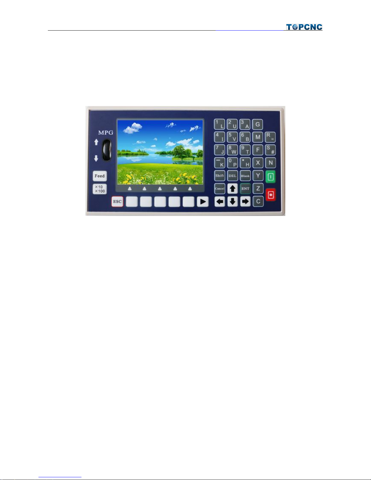
TC55H is an upgrading version of TC55. It can control 4 feeding axis, 1 analog spindle. It is equipped with 16
input port and 8 output port, supporting importing files from USB stick.
2. Technical Specifications
Minimum data unit 0.001 mm
Maximum data size ± 99999.999mm
Maximum Speed: 9000mm/min (pulse is 0.001mm)
Maximum pulse output frequency 150KHz
Axis 1-4 (X,Y, Z,C)
X,Y,Z,C axis can conduct linear interpolation, X,Y can do circular interpolation.
Electric Gear: numerator :1-99999 denominator: 1-99999
USB: Importing program and boot picture
Isolated I/O port
Maximum Program Line: 5000
Maximum Program: 100
RAM: 128M
External Manual Operation: motor clockwise and counter clockwise spinning, start, pause, alert and stop
G code and M code
One panel MPG
3.5 inch color LCD, pixel 320*240
Analog Spindle Output: 1 0-10v analog spindle
Definition of external Switch
jiafengqi.xtf@hotmail.com
3
Operation
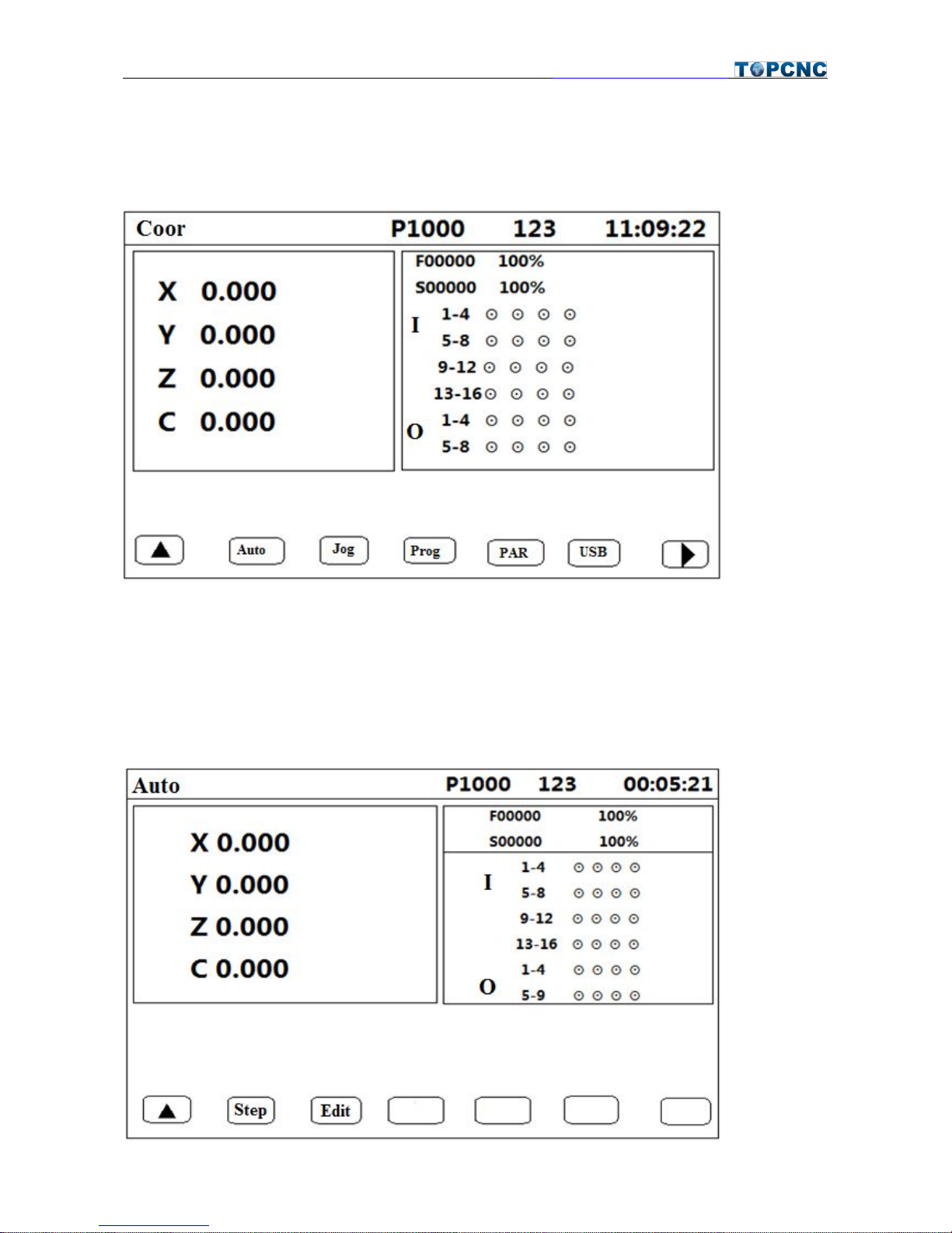
1. Main Interface
This is the interface showing after booting without boot picture. It shows the coordinates of each axis, F
speed and rate, S speed and rate, as well as condition of input and output port. P1000 means the program
currently running; 123 means the input method. You can get into the AUTO, JOG, PROG, PAR, USB as well
as password interface from here.
2.Auto
jiafengqi.xtf@hotmail.com
4
In Auto Interface, Press start to run the last read program, Press Pause to Stop.
2.1 Step
Positive display means consecutive operation. Negative display means operate command by command.
When it is negative display, press Start once, one program line will be executed.
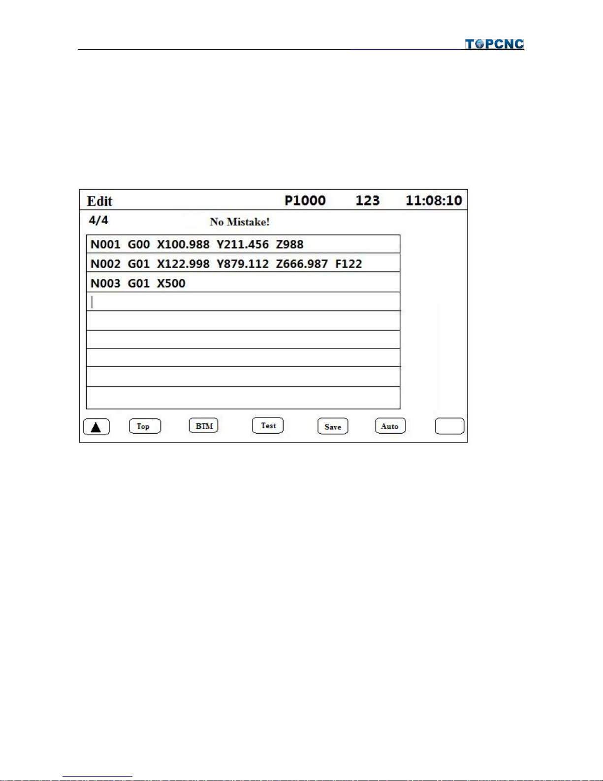
3.4.2 Edit
● Press Enter to insert new line.
● Long press DEL to delete a line.
● Press←→↑↓to move the cursor
● Top: To the fist line
● BTM: to the last line
● Test: See if there are any mistake
● Save: Save program
● Auto: Into Auto Interface.
jiafengqi.xtf@hotmail.com
5
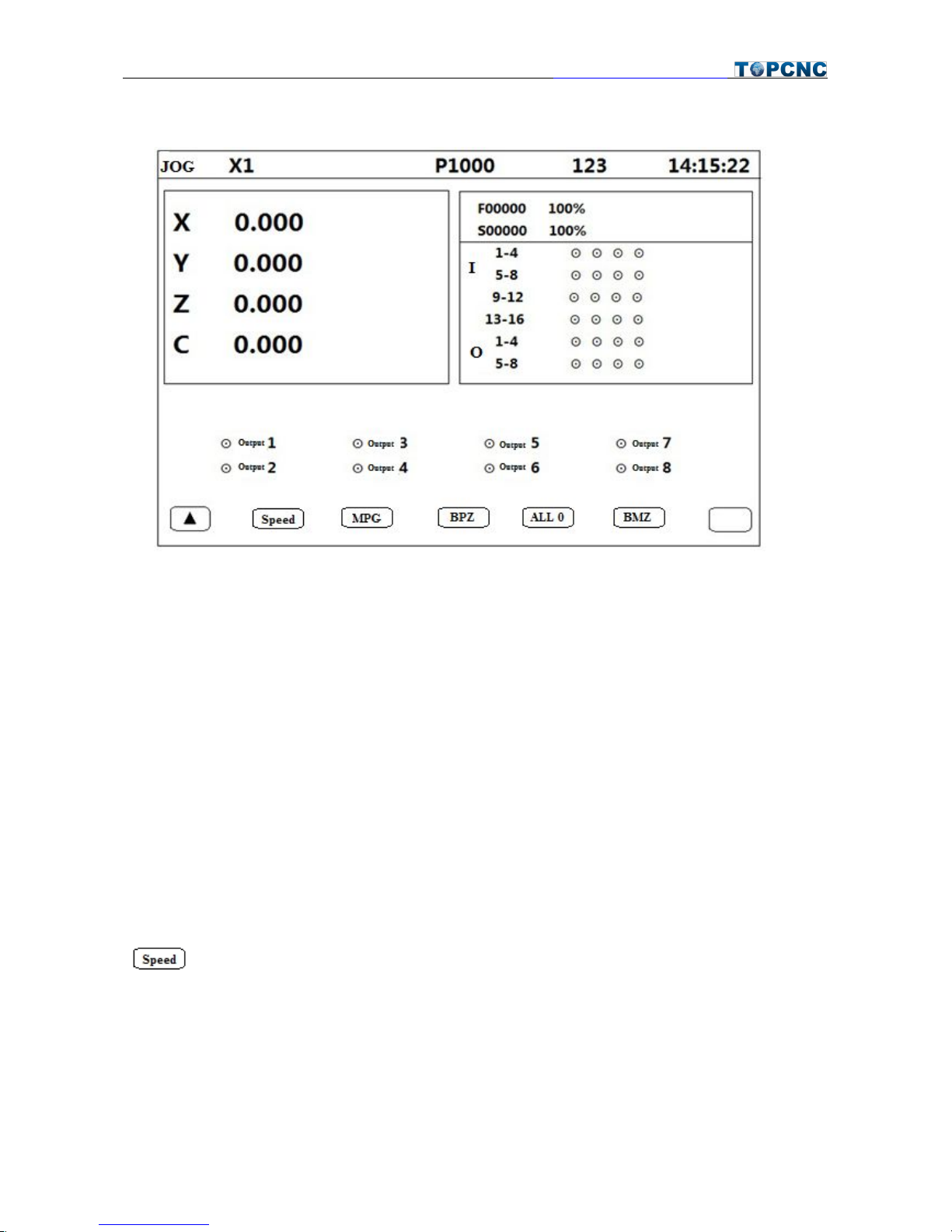
3. Jog
● Press X, Y, Z and C to choose relevant axis.
● S for feeding rate gaining, N for feeding rate decreasing. (10%-150%)
● G for spindle rate gaining, M for spindle rate decreasing. (10%-150%)
● Press Shift to change output port, press Enter to change from ON or OFF.
● Press ← and → for consecutive running.
● Press ↑ and ↓ for jogging, define the jog distance in PAR-Ctrl-Jog+Distance; define jog speed in
PAR-Speed-Jog.
3.1 Speed
: Negative display means manual high speed, positive display means manual low speed. Press ←
and → for consecutive running.

jiafengqi.xtf@hotmail.com
6
3.2 MPG
Press MPG, then move the wheel up, the axis chosen move positively, move the wheel down, the chosen
axis move negatively. Press X10X100 to change the cardinal number which shown on the top of the screen.
Status
Cardinal Number
X1
0.001mm
X10
0.01mm
X100
0.1mm
3.3 BPZ
Press this key the chosen axis go back to reference point at highest speed. Define the highest speed in
Parameters-Speed.
3.4 All 0
Press this key the chosen axis go back to reference point at highest speed. Define the highest speed in
Parameters-Speed. F is the combination speed of all axis.
3.5 BMZ
Return to machine zero. The chosen axis will move at BMZ High Speed to go back to machine zero, then
touch the switch and move at BMZ Low Speed, finally stop on the switch. In order to use this function, the X
0/Y 0/Z 0/C 0 has to be set as “On” in Parameters-Ctrl; Set BMZ High and BMZ Low in Parameters-Speed;
Set the direction in Parameters-Ctrl-X BMZ Dir
4. PAR
4.1 Ctrl
Control parameters setting area, Long press ↑ and ↓ to change page.
X/Y/Z/C Numerator: Electric gear ratio (1-99999)
X/Y/Z/C Denominator: Electric gear ratio(1-99999)
X/Y/Z/C Reference:In manual operation, long press X/Y/Z/C to clear the coordinates and show this
value; or in machine zero, after hit the switch, it will show this value.
X/Y/Z/C Backlash: Backlash to make it more precise
X/Y/Z/C Boot Zero: 0 means the axis will not go back to machine zero after booting; 1 means the axis
will go back to machine zero after booting
X/Y/Z/C BMZ Dir: 0 means the axis go back to machine zero towards negative direction; 1 means the
axis go back to machine zero towards positive direction

jiafengqi.xtf@hotmail.com
7
Speed+Time(ms): time use for motor to reach F speed
Jog+Distance: in manual operation, increment for jogging. Unit of it is depended on electric gear ratio.
Language: English (0)or Chinese(1)
4.1.1 Setting of Electronic Gear Ratio
Setting the electronic gear is to set different data unit for different machines. Different axis of the same
machine can be set based on different unit. For example, axis A can be set as mm, axis B can be set as angle,
and axis C can be set as round.
How to set the numerator and denominator of electronic gear ratio:
Pulse needed for the motor to turn one round to the same direction
Distance moved when the motor turn one round to the same direction(μm)
Numerator and denominator both should be integer between 1 and 99999.
Ex. 1 Screw Transmission
Stepper motor stepping is 5000, or servo motor 5000 pulse/round, screw pitch is 6mm, reduction ratio is 1:1,
then,
5000 → 5
6*1000*1.0 → 6
Ex. 2 Rack and Pinion
Stepper motor stepping is 6000, or servo motor 6000 pulse/round, gear teeth number is 20, m=p/π=2, then
6000 → 1 → 107 → 107
1000*20*2*3.14159265 → 20.943951 → 2241.00276 → 2241
Ex. 3 Rotary Angle
Stepper motor stepping is 5000, or servo motor 5000 pulse/round, reduction ratio is 1:30, then,
5000*30 → 5
360*1000 → 12
4.2 Speed
● X/Y/Z/C Highest: The highest speed of x axis motor. When the system is operating, speed will not
exceed this number no matter what F you set.
● Start(mm/min)Speed during Spd+Time
● Man High: Manual high speed
● Man Low: Manual low speed
 Loading...