

Topcnc TC5510, TC5522, TC5530, TC5530R, TC5522R User Manual
TC5510/TC5522/TC5530/TC5522R/TC5530R
TC5510/TC5522/TC5530/TC5522R/TC5530R
TC5510/TC5522/TC5530/TC5522R/TC5530R
TC5510/TC5522/TC5530/TC5522R/TC5530R
Motion
Motion
Motion
Motion Controller
Controller
Controller
Controller (Stepping
(Stepping
(Stepping
(Stepping Motor
Motor
Motor
Motor Controller)
Controller)
Controller)
Controller) Manual
Manual
Manual
Manual
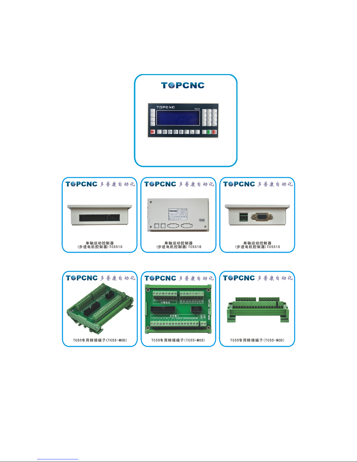
Full figure
Left View Back view Right View
TC55 Breakout Board (TC55-MOD)

Note:
Note:
Note:
Note: The
The
The
The TC55
TC55
TC55
TC55 series
series
series
series are
are
are
are exactly
exactly
exactly
exactly the
the
the
the same
same
same
same panel
panel
panel
panel size
size
size
size and
and
and
and shell
shell
shell
shell film.
film.
film.
film.
TC55-MOD
TC55-MOD
TC55-MOD
TC55-MOD is
is
is
is an
an
an
an optional
optional
optional
optional product.
product.
product.
product.
1. Outline .................................................................................................................................................................... 3
2. Connection .............................................................................................................................................................. 6
3. Operation ................................................................................................................................................................ 9
3.1 AutoExec(Automatically execute) .............................................................................................................. 14
3.1.1 Actl Run(Actual running) ................................................................................................................ 14
3.1.2 Mt Run(Empty running) .................................................................................................................. 15
3.1.3 SS Mo(Single-step execution) ......................................................................................................... 16
3.1.4 TrmtProg(Terminate program) ......................................................................................................... 16
3.2 Man Op(Manual operation) ........................................................................................................................ 17
3.2.1 Man HSpd(Manual high speed) ....................................................................................................... 17
3.2.2 Jog Op(Jog operation) ..................................................................................................................... 18
3.2.3 BkTProg0(Back to program zero) ................................................................................................... 19
3.2.4 BkTMech0(Back to mechanical zero) ............................................................................................. 19
3.3 ProgMgmt(Program Management) ............................................................................................................. 22
3.3.1 Ed Prog(Edit program) .................................................................................................................... 22
3.3.2 Prog RI(Program read-in) ................................................................................................................ 26
3.3.3 Del Prog(Delete program) ............................................................................................................... 26
3.3.4 Sv Prog(Save program) ................................................................................................................... 27
3.4 Pars Set(Parameters settings) ...................................................................................................................... 28
3.4.1 Sys Pars(System parameters) ........................................................................................................... 29
3.4.2 Sys SC(System self-check) .............................................................................................................. 33
3.4.3 IO Set(IO settings) ........................................................................................................................... 38
3.4.4 Usr Mgmt(User management) ......................................................................................................... 42
4. Programming ........................................................................................................................................................ 44
5. Appendix .............................................................................................................................................................. 70
6. Acronyms and Abbreviations ................................................................................................................................ 73

1.
1.
1.
1. Outline
Outline
Outline
Outline
The TC55 panel-type motion controller (CNC system) uses high-performance
32-bit CPU. The drive device adopts subdivision stepping motor or AC servo motor.
It is equipped with LCD monitor and fully enclosed touch-type operating keyboard.
The system has high reliability, high precision, low noise, easy to operate etc. This
controller can control 1-3 motor motion and realize Point to Point, linear interpolation,
circular interpolation and other operations. It has loop, jump and simple PLC
functions etc. Simple and clear parameters bring you convenient and fast operation.
Input/output setting functions are convenient for your to use and maintain
,
and
applicable to all kinds of 1-3 axis motion device.
Product
Product
Product
Product features:
features:
features:
features:
The boot screen can be modified
Controller or upper computer dual-mode programming
Independent 24V power supply reverse connection protection
IO optically-coupled isolation
Output short circuit protection
Manual positive or reverse rotation can be controlled by the external switches
synchronously
Simple PLC logic
The parameter area password can be set

Applicable product type:
l CNC drilling machine system, CNC lathe system, CNC milling machine system,
CNC grinding machine system
l cutting machine control system, welding control system, dispenser control system,
feeding control system
l displacement platform, one-dimensional control platform, two-dimensional
control platform, three-dimensional control platform
l threading machine control system, screwdriving machine control system
l spraying production line control system, assembly production line control system,
the meter counter control system
Technical
Technical
Technical
Technical characteristics:
characteristics:
characteristics:
characteristics:
�
Automatically execute
:
Actual running, Empty running, Single-step execution,
Terminate program, Start and Pause function
�
Manual operation
:
Manual high speed, Manual low speed, Jog operation, Back to
program zero, Back to mechanical zero
�
Program management
:
Edit program, Program read-in, Delete program, Save
program
�
Parameter settings
:
Set various control parameters of processing and operation,
get the best status of processing effect
System
System
System
System parameters:
parameters:
parameters:
parameters:

High-performance, high-speed 32-bit CPU
High-grade black and white double color LCD monitor (resolution: 192 × 64)
Special motion control chip (signal output: 5V TTL)
Universal customizable input / output (16 photoelectric isolated 24V inputs, 8 relay
outputs)
User processing program memory (can store 20 programs)
Minimum data unit 0.001 mm
Maximum data size ± 99999.999mm
Maximum pulse output frequency 150KHz
System main functions are automatic, manual, program editing, system parameters,
self-check, settings, etc.
Installation:
Installation:
Installation:
Installation:
panel type installation structure
dimension 172 x 94 x 30, installing size 164 x 86
Power supply requirements
≥ DC 24V/40W
Environmental requirements
working temperature: 0 ~ 60
℃
relative humidity: 5 ~ 90% no condensation
2.
2.
2.
2. Connection
Connection
Connection
Connection
2.1
2.1
2.1
2.1 Pulse
Pulse
Pulse
Pulse interfaces
interfaces
interfaces
interfaces and
and
and
and drives
drives
drives
drives wiring
wiring
wiring
wiring diagram
diagram
diagram
diagram
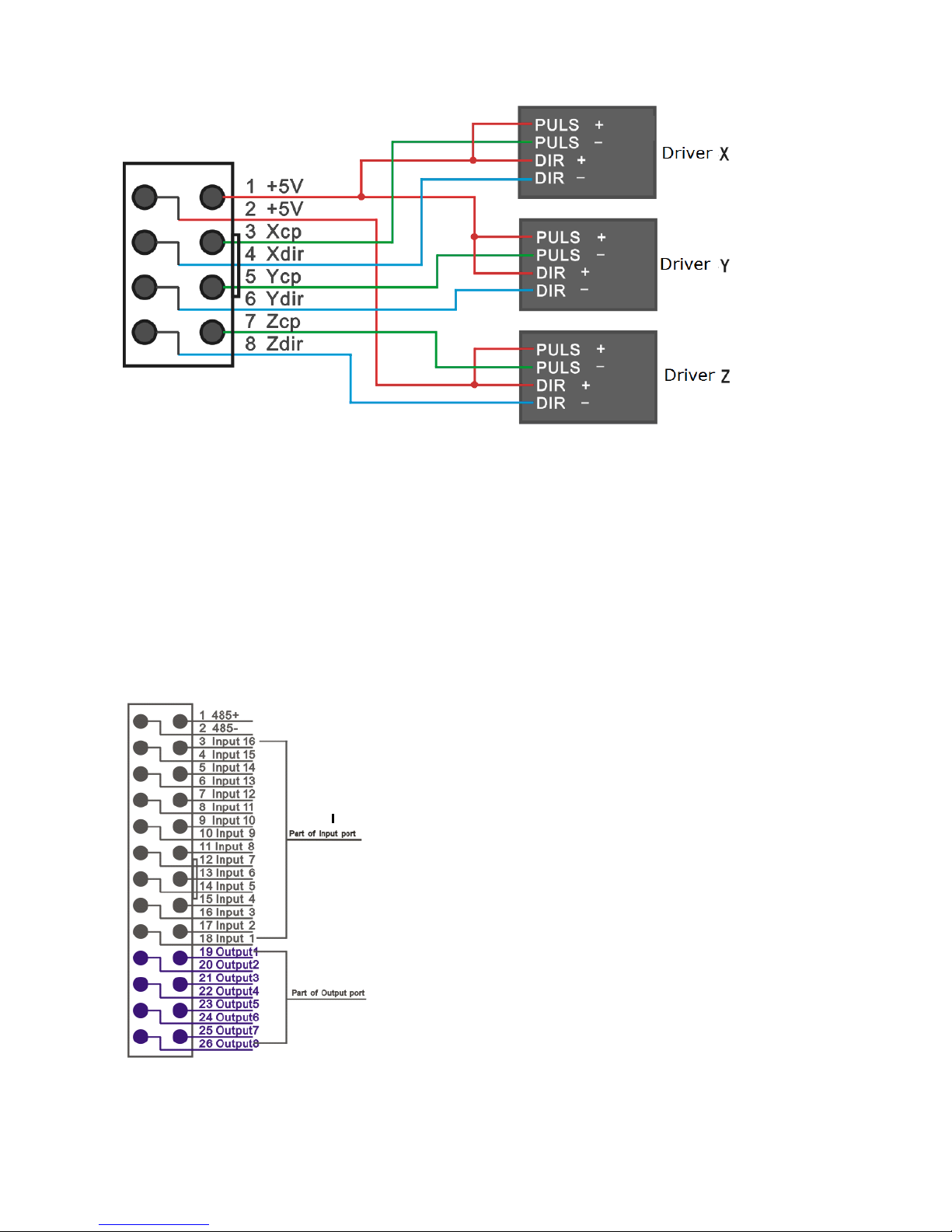
Note:
Note:
Note:
Note: the
the
the
the red
red
red
red line
line
line
line is
is
is
is No.1
No.1
No.1
No.1 pin
pin
pin
pin
TC5510
TC5510
TC5510
TC5510 only
only
only
only take
take
take
take the
the
the
the first
first
first
first 4
4
4
4 wires
wires
wires
wires or
or
or
or terminals
terminals
terminals
terminals of
of
of
of
8P.
8P.
8P.
8P.
Similarly
Similarly
Similarly
Similarly TC5522
TC5522
TC5522
TC5522 or
or
or
or
TC5522R
TC5522R
TC5522R
TC5522R only
only
only
only take
take
take
take the
the
the
the first
first
first
first 6
6
6
6 wires
wires
wires
wires or
or
or
or terminals
terminals
terminals
terminals of
of
of
of
8P.
8P.
8P.
8P.
2.2
2.2
2.2
2.2 Input/output
Input/output
Input/output
Input/output and
and
and
and switches
switches
switches
switches and
and
and
and relays
relays
relays
relays wiring
wiring
wiring
wiring diagram.
diagram.
diagram.
diagram.
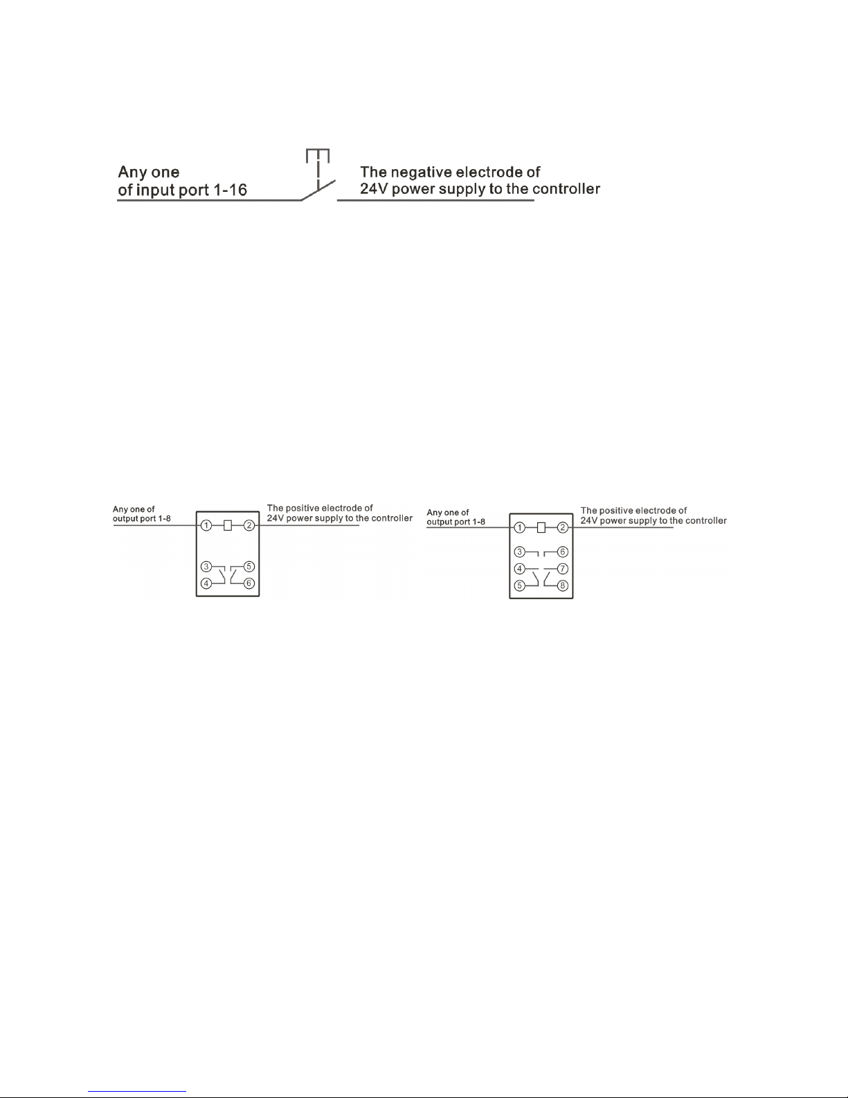
2.2.1
2.2.1
2.2.1
2.2.1 Input
Input
Input
Input wiring
wiring
wiring
wiring diagram
diagram
diagram
diagram
Any
Any
Any
Any one
one
one
one of
of
of
of input
input
input
input port
port
port
port 1-16
1-16
1-16
1-16
The
The
The
The negative
negative
negative
negative electrode
electrode
electrode
electrode of
of
of
of 24V
24V
24V
24V power
power
power
power supply
supply
supply
supply to
to
to
to the
the
the
the controller
controller
controller
controller
The picture shows the two-wire standard mechanical switch and photoelectric
switch connection method. One end of the switch is connected to the selected and
defined input line. The other end of the switch must be connected to the negative
electrode of 24V power supply to the controller.
Note: the photoelectric switch must be NPN type.
2.2.2
2.2.2
2.2.2
2.2.2 Output
Output
Output
Output line
line
line
line wiring
wiring
wiring
wiring diagram
diagram
diagram
diagram
Any
Any
Any
Any one
one
one
one of
of
of
of output
output
output
output port
port
port
port 1-8
1-8
1-8
1-8
The
The
The
The positive
positive
positive
positive electrode
electrode
electrode
electrode of
of
of
of 24V
24V
24V
24V power
power
power
power supply
supply
supply
supply to
to
to
to the
the
the
the controller
controller
controller
controller
As shown in figure, contacts 1 and 2 are the coil contacts of relay.
Output line is connected to one end of the relay coil. The other end of the coil is
connected to the positive electrode of 24V power supply to the controller.
Note
Note
Note
Note 1:
1:
1:
1: If
If
If
If the
the
the
the connected
connected
connected
connected relay
relay
relay
relay or
or
or
or other
other
other
other electrical
electrical
electrical
electrical component
component
component
component is
is
is
is required
required
required
required for
for
for
for
power
power
power
power supply
supply
supply
supply positive
positive
positive
positive or
or
or
or negative
negative
negative
negative access,
access,
access,
access, then
then
then
then wire
wire
wire
wire according
according
according
according to
to
to
to the
the
the
the electrical
electrical
electrical
electrical
diagram
diagram
diagram
diagram of
of
of
of the
the
the
the relay
relay
relay
relay or
or
or
or the
the
the
the electrical
electrical
electrical
electrical component.
component.
component.
component.
Note
Note
Note
Note 2:
2:
2:
2: the
the
the
the red
red
red
red line
line
line
line is
is
is
is No.1
No.1
No.1
No.1 pin
pin
pin
pin
Any
Any
Any
Any one
one
one
one of
of
of
of input
input
input
input port
port
port
port 1-16
1-16
1-16
1-16 can
can
can
can be
be
be
be connected
connected
connected
connected to
to
to
to one
one
one
one end
end
end
end of
of
of
of the
the
the
the switch.
switch.
switch.
switch. The
The
The
The
specific
specific
specific
specific switch
switch
switch
switch definition
definition
definition
definition depends
depends
depends
depends on
on
on
on the
the
the
the input
input
input
input parameter
parameter
parameter
parameter values
values
values
values of
of
of
of IO
IO
IO
IO settings
settings
settings
settings of
of
of
of
the
the
the
the controller
controller
controller
controller parameters
parameters
parameters
parameters area.
area.
area.
area. The
The
The
The other
other
other
other end
end
end
end of
of
of
of the
the
the
the switch
switch
switch
switch must
must
must
must be
be
be
be connected
connected
connected
connected to
to
to
to
the
the
the
the negative
negative
negative
negative electrode
electrode
electrode
electrode of
of
of
of 24V
24V
24V
24V power
power
power
power supply
supply
supply
supply to
to
to
to the
the
the
the controller.
controller.
controller.
controller.
Any
Any
Any
Any one
one
one
one of
of
of
of output
output
output
output port
port
port
port 1-8
1-8
1-8
1-8 can
can
can
can be
be
be
be connected
connected
connected
connected to
to
to
to one
one
one
one end
end
end
end of
of
of
of the
the
the
the relay
relay
relay
relay coil.
coil.
coil.
coil.
The
The
The
The specific
specific
specific
specific output
output
output
output port
port
port
port definition
definition
definition
definition depends
depends
depends
depends on
on
on
on the
the
the
the output
output
output
output parameter
parameter
parameter
parameter values
values
values
values of
of
of
of
IO
IO
IO
IO settings
settings
settings
settings of
of
of
of the
the
the
the controller
controller
controller
controller parameters
parameters
parameters
parameters area.
area.
area.
area. The
The
The
The other
other
other
other end
end
end
end of
of
of
of the
the
the
the relay
relay
relay
relay coil
coil
coil
coil
must
must
must
must be
be
be
be connected
connected
connected
connected to
to
to
to the
the
the
the positive
positive
positive
positive electrode
electrode
electrode
electrode of
of
of
of 24V
24V
24V
24V power
power
power
power supply
supply
supply
supply to
to
to
to the
the
the
the
controller.
controller.
controller.
controller.
Controller
Controller
Controller
Controller power
power
power
power supply
supply
supply
supply interface
interface
interface
interface definition
definition
definition
definition is
is
is
is on
on
on
on the
the
the
the back
back
back
back of
of
of
of the
the
the
the controller
controller
controller
controller
shell.
shell.
shell.
shell. Please
Please
Please
Please wire
wire
wire
wire according
according
according
according to
to
to
to the
the
the
the mark
mark
mark
mark on
on
on
on the
the
the
the back.
back.
back.
back. The
The
The
The power
power
power
power supply
supply
supply
supply is
is
is
is 24V
24V
24V
24V
DC.
DC.
DC.
DC. Power
Power
Power
Power is
is
is
is not
not
not
not less
less
less
less than
than
than
than 40W.
40W.
40W.
40W.
3.
3.
3.
3. Operation
Operation
Operation
Operation
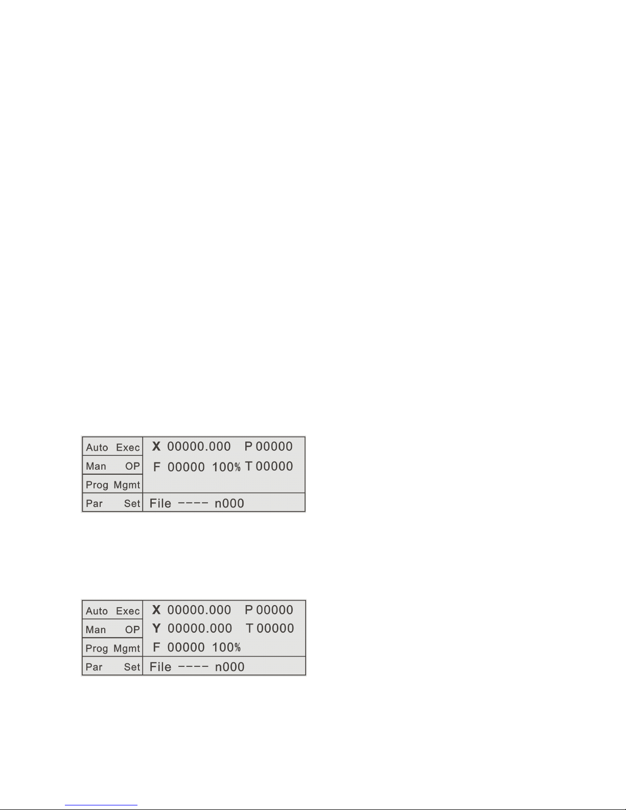
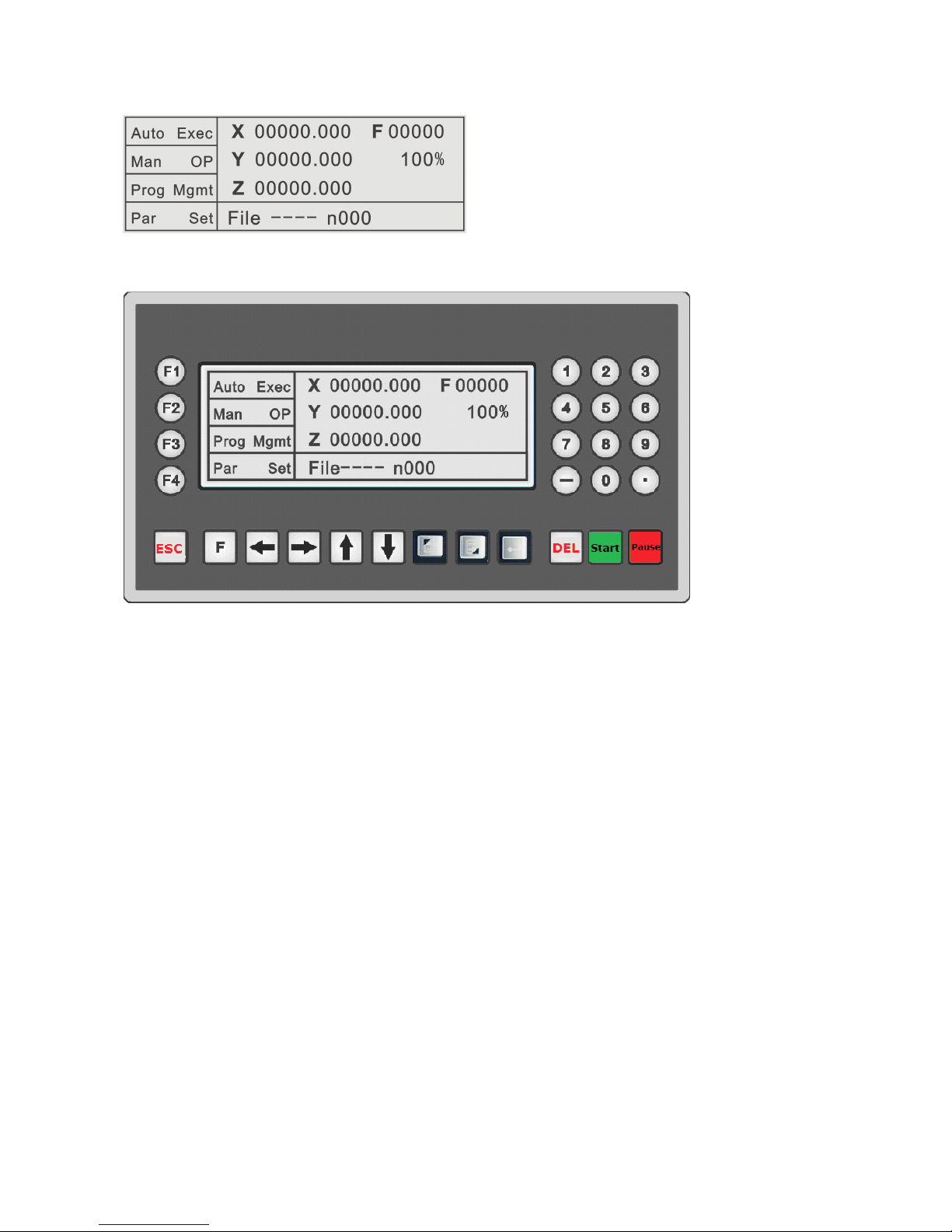
Boot and enter into the main operation interface after showing the boot screen
AutoExec Automatically execute
Man OP Manual operation
ProgMgmt Program management
File
Pars Set Parameter settings
The picture shows the main interface of TC5510 after boot.
The picture shows the main interface of TC5522 or TC5522R after boot.
The picture shows the main interface of TC5530 or TC5530R after boot.
1.
1.
1.
1. The
The
The
The screen
screen
screen
screen area
area
area
area
AutoExec
:
Automatically execute. Click to enter the program execution interface,
including the default Actl Run(Actual running), Mt Run (Empty running),
SS Mo(Single-step mode running), TrmtProg(Terminate program).
Man OP: Manual operation. Click to enter the manual operation interface, including
the default Man LSpd(Manual low speed), Man HSpd(Manual high
speed), Jog Op(Jog operation), BkTProg0(Back to program zero),
BkTMech0(Back to mechanical zero).
ProgMgmt: Program management. Click to enter the program editing interface,
including Ed Prog(Edit program), Prog RI(Program read-in), Del
Prog(Delete program), Sv Prog(Save program).

Pars Set: Parameters settings. Click to enter the parameter setting interface, including
Sys Pars(System parameters), Sys SC(System self-check), IO Set(IO
settings), Usr Mgmt(User management).
X
X
X
X
:
The current coordinate position
Y
Y
Y
Y
:
The current coordinate position
Z
Z
Z
Z
:
The current coordinate position
F
F
F
F
:
The current running speed
Unit: subject to the selected electronic gear calculation formula. When electronic gear
default is 1:1, the unit default is the pulse number.
100%
100%
100%
100%
:
the speed percentage (rate) of the current F value
P
P
P
P
:
the countdown of loops
T
T
T
T
:
the countdown of delay time
2.
2.
2.
2. The
The
The
The Key
Key
Key
Key area
area
area
area
F1
F1
F1
F1
:
In the current state, the function key corresponding to the F1 key position, is
valid in the current state.
F2
F2
F2
F2
:
In the current state, the function key corresponding to the F2 key position, is
valid in the current state.
F3
F3
F3
F3
:
In the current state, the function key corresponding to the F3 key position, is
valid in the current state.
F4
F4
F4
F4
:
In the current state, the function key corresponding to the F4 key position, is
valid in the current state.

0-9
0-9
0-9
0-9
:
Valid in the Ed Prog(Edit program) state or Pars Set(Parameters settings) state.
(
0
、
1
、
2
、
3
、
4
、
5
、
6
、
7
、
8
、
9
)
1-3
1-3
1-3
1-3
:
In the Man Op(Manual operation) state, long press 1 key for three seconds, you
can modify the X-axis coordinate to "X-axis mechanical reference point value",
which is set in the Sys Pars(System parameters) area of Pars Set (Parameters
settings) area. In the Man Op(Manual operation) state, long press 2 key for
three seconds, you can modify the Y-axis coordinate to "Y -axis mechanical
reference point value", which is set in the Sys Pars(System parameters) area of
Pars Set (Parameters settings) area. In the Man Op(Manual operation) state,
long press 3 key for three seconds, you can modify the Z-axis coordinate to
"Z-axis mechanical reference point value", which is set in the Sys Pars(System
parameters) area of Pars Set (Parameters settings) area. The three values
defaults are 0.
“
“
“
“ -
-
-
- ”
”
”
”
:
In the Ed Prog(Edit program) state, it is used to distinguish between movement
direction. In the Man Op(Manual operation) state, it is used to operate the
Z-axis reverse rotation.
“
“
“
“ .
.
.
. ”
”
”
”
:
In the Ed Prog(Edit program) state, it is used to distinguish between numerical
accuracy. In the Man Op(Manual operation) state, it is used to operate the
Z-axis forward rotation.
Exit
Exit
Exit
Exit : Invalid in the program running process and valid in the rest of the state. It is
used to return to previous operation interface.
“←”
“←”
“←”
“←”
:
In the Man Op(Manual operation) state, X-axis is reverse rotation. It is valid in

the ProgMgmt(Program management) state or Pars Set(Parameters settings)
state and used to move the cursor.
“→”
“→”
“→”
“→”
:
In the Man Op(Manual operation) state, X-axis is forward rotation. It is valid in
the ProgMgmt(Program management) state or Pars Set(Parameters settings)
state and used to move the cursor.
“↑”
“↑”
“↑”
“↑”
:
In the Man Op(Manual operation) state, Y -axis is forward rotation. It is valid in
the ProgMgmt(Program management) state or Pars Set(Parameters settings)
state and used to move the cursor.
“↓”
“↓”
“↓”
“↓”
:
In the Man Op(Manual operation) state, Y-axis is reverse rotation. It is valid in
the ProgMgmt(Program management) state or Pars Set(Parameters settings)
state and used to move the cursor.
PgUp
PgUp
PgUp
PgUp : PageUp. In the main interface, AutoExec(Automatically execute) or Man
Op(Manual operation) state
,
it is the rate+ key of the speed F value and used to
increase rate of the current speed F value, maximum to 150%. In the
ProgMgmt(Program management) state or Pars Set(Parameters settings) state,
it is used to page up the current page.
PgDn
PgDn
PgDn
PgDn : PageDown. In the main interface, AutoExec(Automatically execute) or Man
Op(Manual operation) state
,
it is the rate- key of the speed F value and used to
reduce rate of the current speed F value, minimum to 10%. In the
ProgMgmt(Program management) state or Pars Set(Parameters settings) state,
it is used to page down the current page.
Cfm:
Cfm:
Cfm:
Cfm: Confirm. Valid in the Pars Set(Parameters settings) state. When modifying
parameters or entering password for user login, press the Cfm(Confirm) key to
determine to modify parameters or user login successfully.
Spc: Space. It is valid in the Ed Prog(Edit program) state or Pars Set(Parameters
settings) state and used to clear(delete) the value of the current cursor position.
St: Start. It is valid in the AutoExec(Automatically execute) state and used to start the
execution of the current program file.
Paus: Pause. It is valid in the AutoExec(Automatically execute) state and used to
pause the execution of the current program file.
3.1
3.1
3.1
3.1 AutoExec(Automatically
AutoExec(Automatically
AutoExec(Automatically
AutoExec(Automatically execute)
execute)
execute)
execute)
(TC5530R is used as an example)
3.1.1
3.1.1
3.1.1
3.1.1 Actl
Actl
Actl
Actl Run(Actual
Run(Actual
Run(Actual
Run(Actual running)
running)
running)
running)
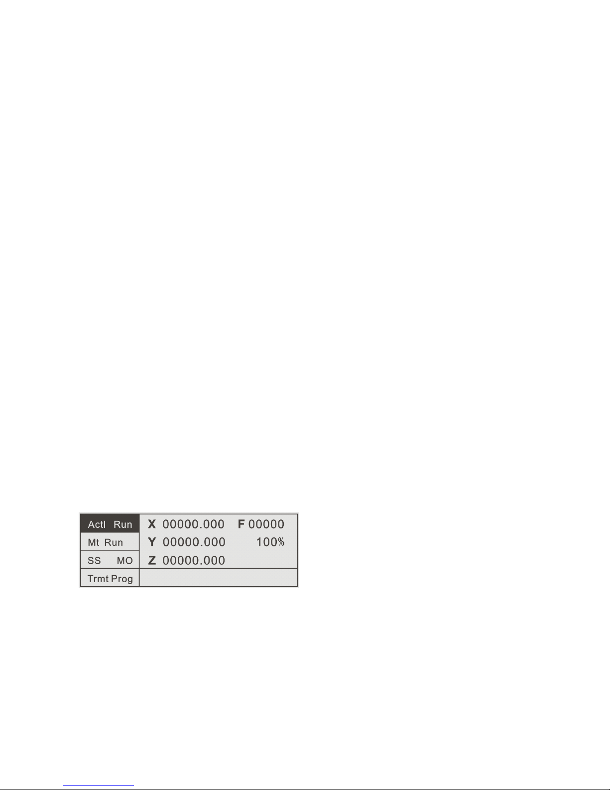
In the main interface, press the left F1 key to enter the AutoExec(Automatically
execute) interface. At this time, the Actl Run(Actual running) key color is negative
display, and the system default is in the Actl Run(Actual running) state in the
program continuous running mode.
Actl Run (Actual running)
Mt Run(Empty running)
SS Mo (Single-step mode)
TrmtProg (Terminate program)
In this state, by pressing the St(Start) key on the controller panel or the external
input line St(Start) key defined in the IO set(IO settings) area of Pars Set (Parameters
settings) area, the controller begins running with the default last read-in program file.
Press the Paus(Pause) key to pause the running program.
To
continue to execute the
paused program file, press the St(Start) key again.
To
exit the program and remain in
the AutoExec(Automatically execute) interface, press the TrmtProg(Terminate
program) key. If want to direct exit to the main interface, the program must be in the
Paus(Pause) or TrmtProg(Terminate program) state, then press the Exit key to return
to the main interface, or the Exit key is invalid.
3.1.2
3.1.2
3.1.2
3.1.2 Mt
Mt
Mt
Mt Run(Empty
Run(Empty
Run(Empty
Run(Empty running)
running)
running)
running)
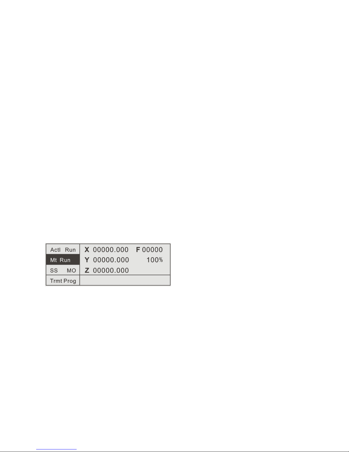
In the AutoExec(Automatically execute) interface, press the left F2 key to enter
the Mt Run(Empty running) state. At this time, the controller Mt Run(Empty running)
key color is negative display, and the system is in the Empty running state in the
program continuous running mode.
Cont Mo (Continuous mode)
In this state, press the St(Start) or Paus(Pause) key on the controller panel or the
external input line St(Start) or Paus(Pause) defined in the IO set(IO settings) area of
Pars Set (Parameters settings) area, to operate Empty running on program. At this
time, the controller program runs normally without any external action. It is often
used for simulation test after program editing and before actual running.
3.1.3
3.1.3
3.1.3
3.1.3 Single-step
Single-step
Single-step
Single-step execution
execution
execution
execution
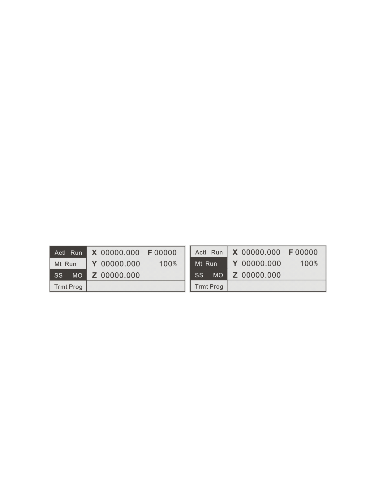
In the Actl Run(Actual running) or Mt Run(Empty running) state, if SS
Mo(Single-step mode) is not chosen, the system default is in the program continuous
running mode and the SS Mo(Single-step mode) key color is not negative display. If
press the left F3 key corresponding to SS Mo(Single-step mode), the SS
Mo(Single-step mode) key color is negative display and in the Actl Run(Actual
running) or Mt Run(Empty running) state, program runs with Single-step mode. Each
step of the program running is controlled by the St(Start) key on the controller panel
or the external input line St(Start) defined in the IO set(IO settings) area of Pars Set
(Parameters settings) area. Press the key, the current file executes a line of program,
press again, then continues to execute next line of program.
3.1.4
3.1.4
3.1.4
3.1.4 TrmtProg(T erminate
TrmtProg(T erminate
TrmtProg(T erminate
TrmtProg(T erminate program)
program)
program)
program)
In the program pause or running state, by pressing this key, the program stops
and jumps to the first line of the program in the AutoExec(Automatically execute)
interface.
3.2
3.2
3.2
3.2 Man
Man
Man
Man Op(Manual
Op(Manual
Op(Manual
Op(Manual operation)
operation)
operation)
operation)
In the main interface, press the left F2 key to enter the Man Op
(
Manual
operation
)
interface.
Man HSpd(Manual high speed)
Jog Op(Jog operation)
BkTProg0(Back to program zero)
BkTMech0(Back to mechanical zero)
At this time, the default is Man LSpd(Manual low speed). The speed parameter
is set in the Spd Pars(Speed parameters) area of the Pars Set(Parameters settings)
area, and is the fixed mode(the rate key is valid ).
Through the keys
(
‘←’‘→’‘↑’‘↓’‘ - ’‘ . ’
)
on the controller panel or the direction
keys of external IO settings, the forward or reverse rotation of the motor can be
controlled.
3.2.1
3.2.1
3.2.1
3.2.1 Man
Man
Man
Man HSpd(Manual
HSpd(Manual
HSpd(Manual
HSpd(Manual high
high
high
high speed)
speed)
speed)
speed)
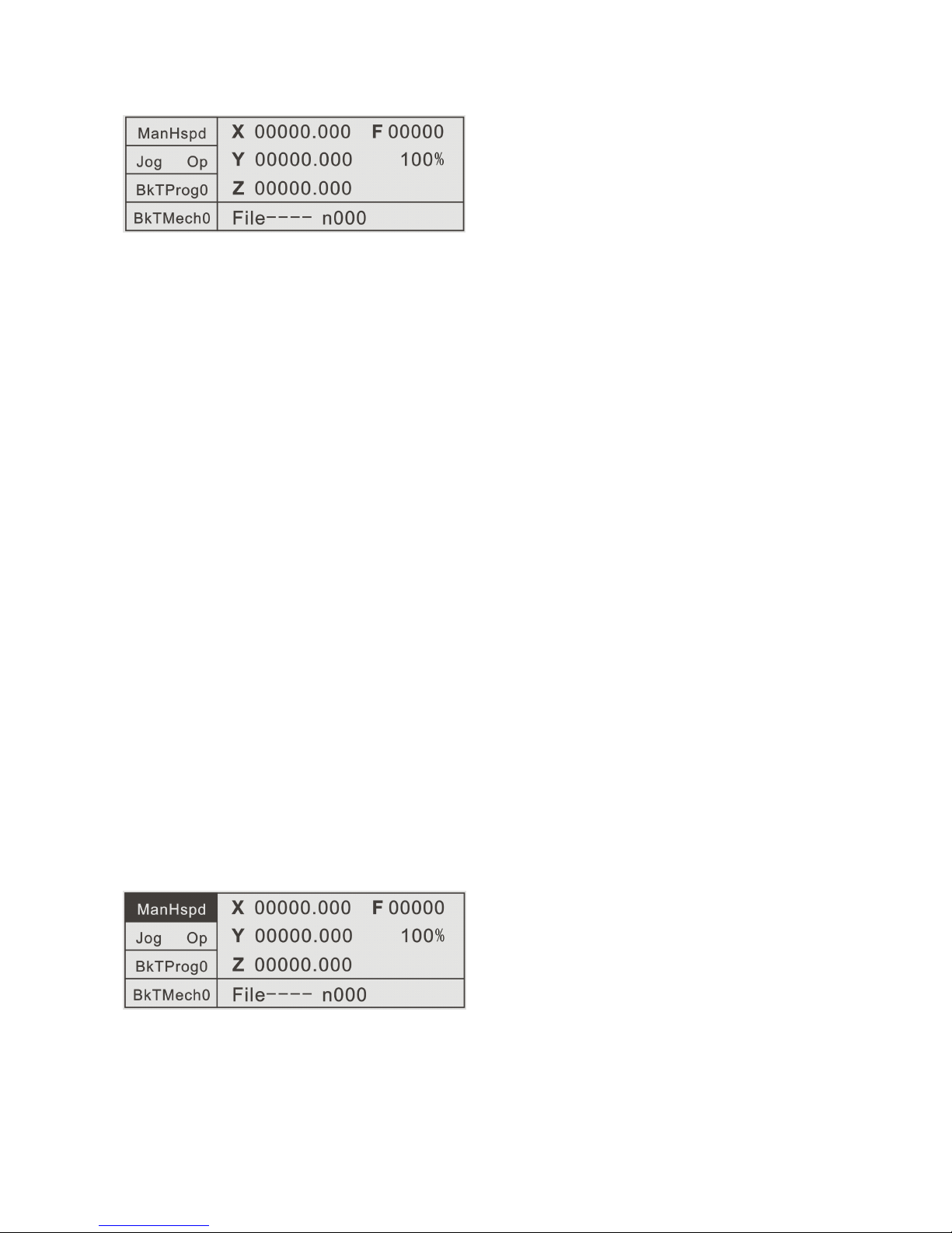
In the Man Op(Manual operation) interface, press the left F1 key to enter the
Man HSpd(Manual high speed) interface. At this time, the Man HSpd(Manual high
speed) key color is negative display, and the system is in the Manual high speed state.
The speed parameter is set in the Spd Pars(Speed parameters) area of the Pars
Set(Parameters settings) area, and is the fixed mode(the rate key is valid ).
Through the keys
(
‘←’‘→’‘↑’‘↓’‘ - ’‘ . ’)on the controller panel or the keys of external
IO settings, the forward or reverse rotation of the motor can be controlled.
3.2.2
3.2.2
3.2.2
3.2.2 Jog
Jog
Jog
Jog Op(Jog
Op(Jog
Op(Jog
Op(Jog operation)
operation)
operation)
operation)
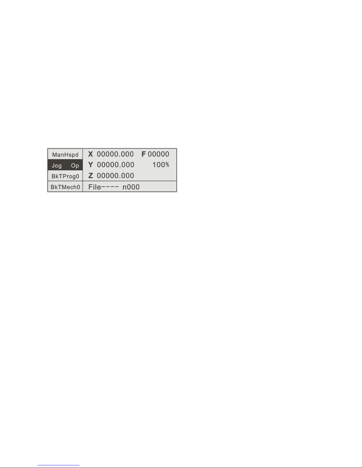
In the Man Op(Manual operation) interface, press the left F2 key to enter the Jog
Op(Jog operation) interface. At this time, the Jog Op(Jog operation) key color is
negative display, and the system is in the Jog operation state. The Jog increment
parameter is set in the CtrlPars(Control parameters) area of the Pars Set(Parameters
settings) area, and is the fixed mode.
Through the keys
(
‘←’‘→’‘↑’‘↓’‘ - ’‘ . ’
)
on the controller panel or the keys of
external IO settings, the forward or reverse rotation of the motor can be controlled
with the already set displacement increment.
3.2.3
3.2.3
3.2.3
3.2.3 BkTProg0(Back
BkTProg0(Back
BkTProg0(Back
BkTProg0(Back to
to
to
to program
program
program
program zero)
zero)
zero)
zero)
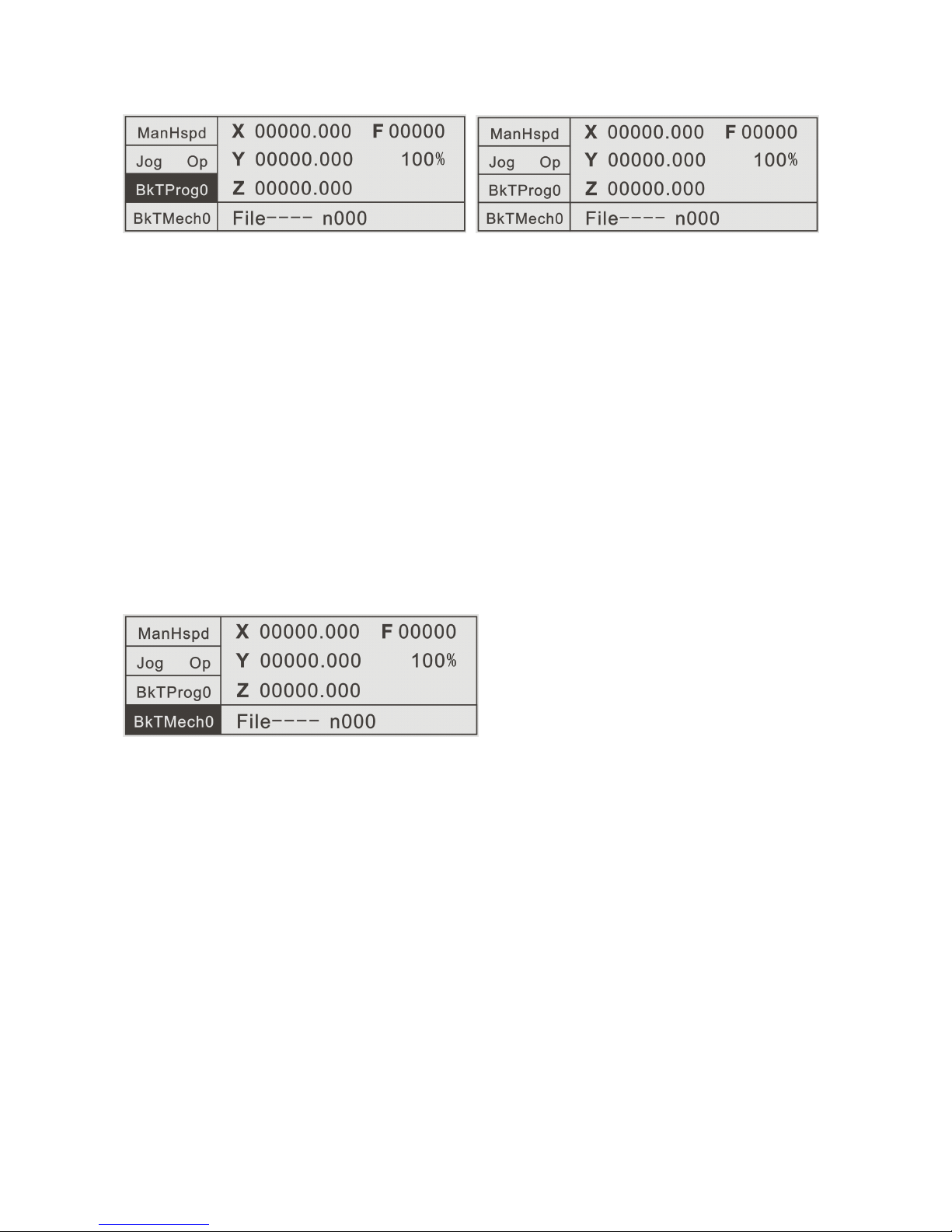
In the Man Op(Manual operation) interface, press the left F3 key to enter the
BkTProg0(Back to program zero) interface. At this time, the BkTProg0(Back to
program zero) key color is negative display, and the system is in the BkTProg0(Back
to program zero) state. The speed parameter is set in the Spd Pars(Speed
parameters) area of the Pars Set(Parameters settings) area, and is the resultant
speed of the system high speed. That is, returning back to the program coordinates
zero in linear interpolation (start at the same time, stop at the same time) mode. At
this time, only Pause is valid. After returning back to the coordinates zero, the key
color negative display is back to the normal status.
3.2.4
3.2.4
3.2.4
3.2.4 BkTMech0(Back
BkTMech0(Back
BkTMech0(Back
BkTMech0(Back to
to
to
to mechanical
mechanical
mechanical
mechanical zero(mechanical
zero(mechanical
zero(mechanical
zero(mechanical reference
reference
reference
reference point))
point))
point))
point))
In the Man Op(Manual operation) interface, press the left F4 key to enter the
BkTMech0(Back to mechanical zero) interface. At this time, the BkTMech0(Back to
mechanical zero) key color is negative display, and the system is in the
BkTMech0(Back to mechanical zero) state. The Bk0 HSpd(Back to zero high speed)
or Bk0 LSpd(Back to zero low speed) speed parameter of Back to mechanical
zero (
(
(
( reference point )
)
)
) is set in the Spd Pars(Speed parameters) area of the Pars
Set(Parameters settings) area, and is the fixed mode(the rate key is valid ).
Through the keys
(
‘←’‘→’‘↑’‘↓’‘ - ’‘ . ’
)
on the controller panel or the direction
keys of external IO settings, the single direction Back to mechanical zero(mechanical
reference point) operation of the motor can be controlled. Before completing the
BkTMech0(Back to mechanical zero) operation, only the Paus(Pause) key is valid.
Back to mechanical zero is a set of combined actions. The premise is first to set
a set of zero point switches(both mechanical and photoelectric switches are allowed),
assuming that the switches are in the N.O.(Normally open) state.
1
)
.Firstly move to the pressed key direction (or the direction specified by the
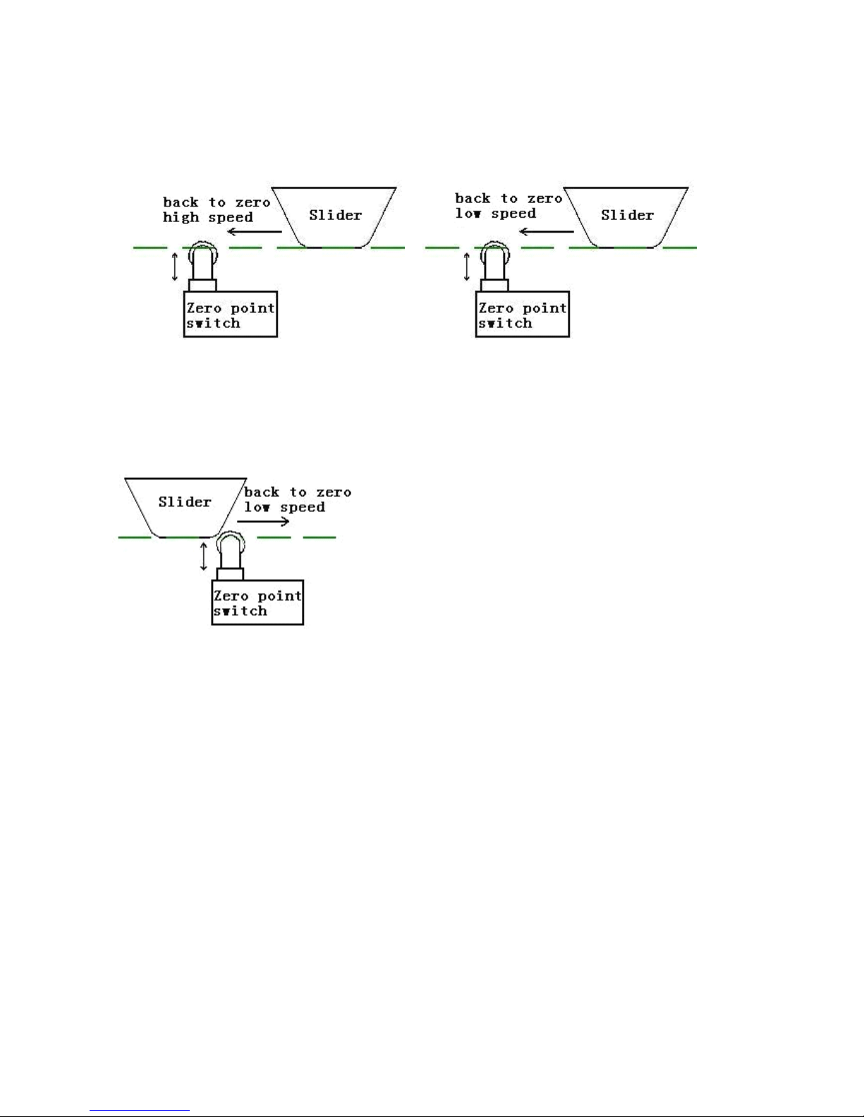
program instructions) with Bk0 HSpd(Back to zero high speed), until touch the zero
point switch of the axis and the switch status changes from Open to Closed.
2
)
.After touching the zero point switch, move with the speed quickly reduced to Bk0
LSpd(Back to zero low speed), until pass the switch and the switch status changes
from Closed to Open.
3
)
. After the switch status changes to Open, the axis will automatically continue to
reverse move with Bk0 LSpd
(
Back to zero low speed
)
, until press the switch again
and the switch changes from Open to Closed secondly. At this time, stop instantly, the
action of Back to mechanical zero is completed and the axis coordinate on the
controller interface changes to the axis reference point value. The axis reference point
value is set in the CtrlPars (Control parameters) area of the Pars Set(Parameters
settings) area.
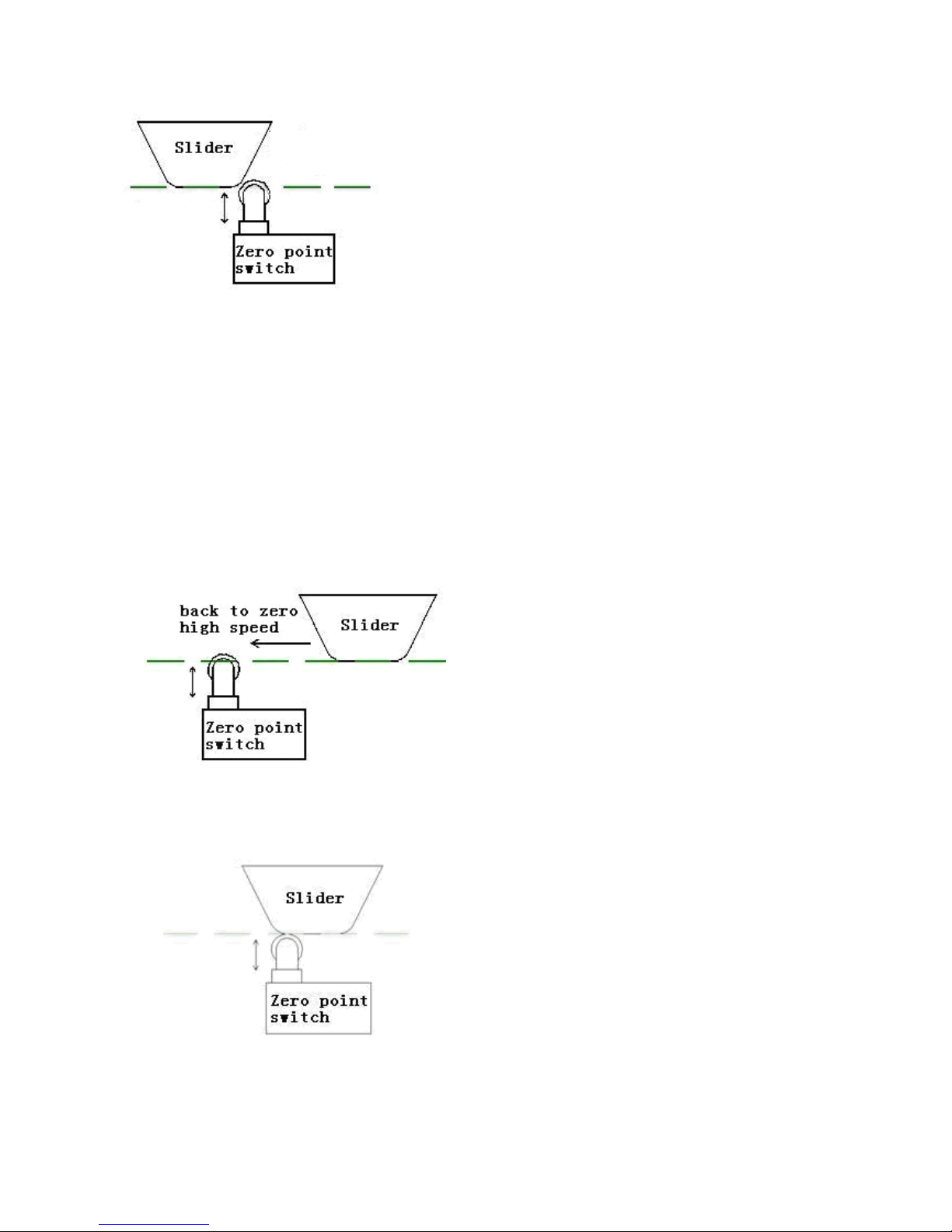
Note: The machine tool limit switch is used as an example in the above figures. Also
the photoelectric switch can be used as the zero point switch, similarly.
Back to zero mode II:
1). Firstly move to the pressed key direction(or the direction specified by the program
instructions) with Bk0 HSpd(Back to zero high speed), until touch the zero point
switch of the axis and the switch status changes from Open to Closed.
2). After the zero point switch is touched, the speed is quickly reduced to zero.
3). Automatically reverse move with Bk0 LSpd
(
Back to zero low speed
)
, until the
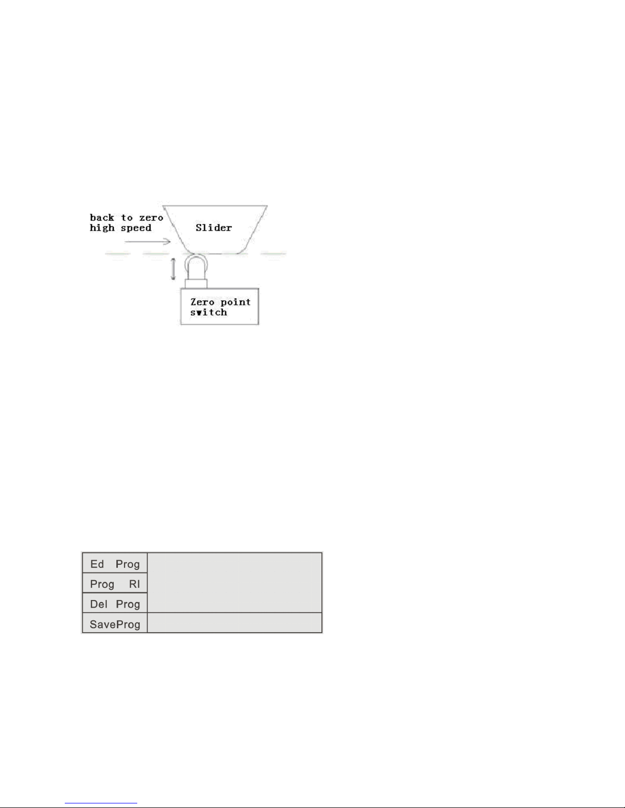
switch changes from Closed to Open. At this time, stop instantly, the action of Back
to mechanical zero is completed and the axis coordinate on the controller interface
changes to the axis reference point value. The axis reference point value is set in the
CtrlPars (Control parameters) area of the Pars Set(Parameters settings) area.
Note: Back to zero mode II has some risk. If adopting this mode, propose that Bk0
HSpd(Back to zero high speed) is set smaller to avoid the slider exceed the zero point
switch when back to zero.
3.3
3.3
3.3
3.3 ProgMgmt(Program
ProgMgmt(Program
ProgMgmt(Program
ProgMgmt(Program Management)
Management)
Management)
Management)
In the main interface, press the left F3 key to enter the ProgMgmt(Program
Management) interface. In this interface, we can operate program to edit, read-in,
delete and save.
Ed Prog Edit program
Prog RI Program read-in
Del Prog Delete program
Sv Prog Save program
3.3.1
3.3.1
3.3.1
3.3.1 Ed
Ed
Ed
Ed Prog(Edit
Prog(Edit
Prog(Edit
Prog(Edit program)
program)
program)
program)
In the ProgMgmt(Program Management) interface, press the left F1 key to enter
the Ed Prog(Edit program) interface. In this interface, we can modify or rebuild the
read-in file or the last open file before the shutdown.
PgUpInst Page up instruction
PgDnInst Page down instruction
Ins 1Row Insert a row
Del 1Row Delete a row
Lin M Linear motion
Lbl Label
Abs M Absolute motion
PTP M Point to Point motion
End End
3.3.1.1
3.3.1.1
3.3.1.1
3.3.1.1 PgUpInst(Page
PgUpInst(Page
PgUpInst(Page
PgUpInst(Page up
up
up
up instruction):
instruction):
instruction):
instruction): In the current line number, through this key,
we can page up all Instruction Names controlled and applied by the controller.
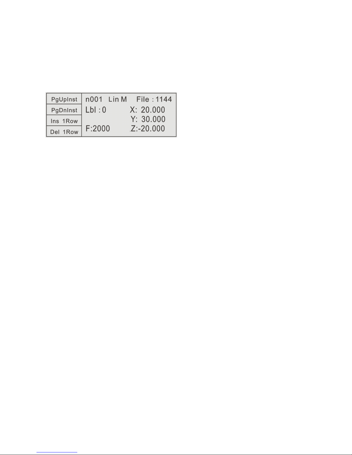
Example:
In the interface,
n001 Lin M File:1144
press PgUpInst once, then becomes
n001 Abs M File: 1144
That is, in the n001 line
,
modify the old Lin M(Linear motion) instruction to the Abs
M
(
Absolute motion
)
instruction, and new instruction parameter shows
simultaneously.
3.3.1.2
3.3.1.2
3.3.1.2
3.3.1.2 PgDnInst(Page
PgDnInst(Page
PgDnInst(Page
PgDnInst(Page down
down
down
down instruction):
instruction):
instruction):
instruction): In the current line number, through this
key, we can page down all Instruction Names controlled and applied by the controller.
 Loading...