

Page 1
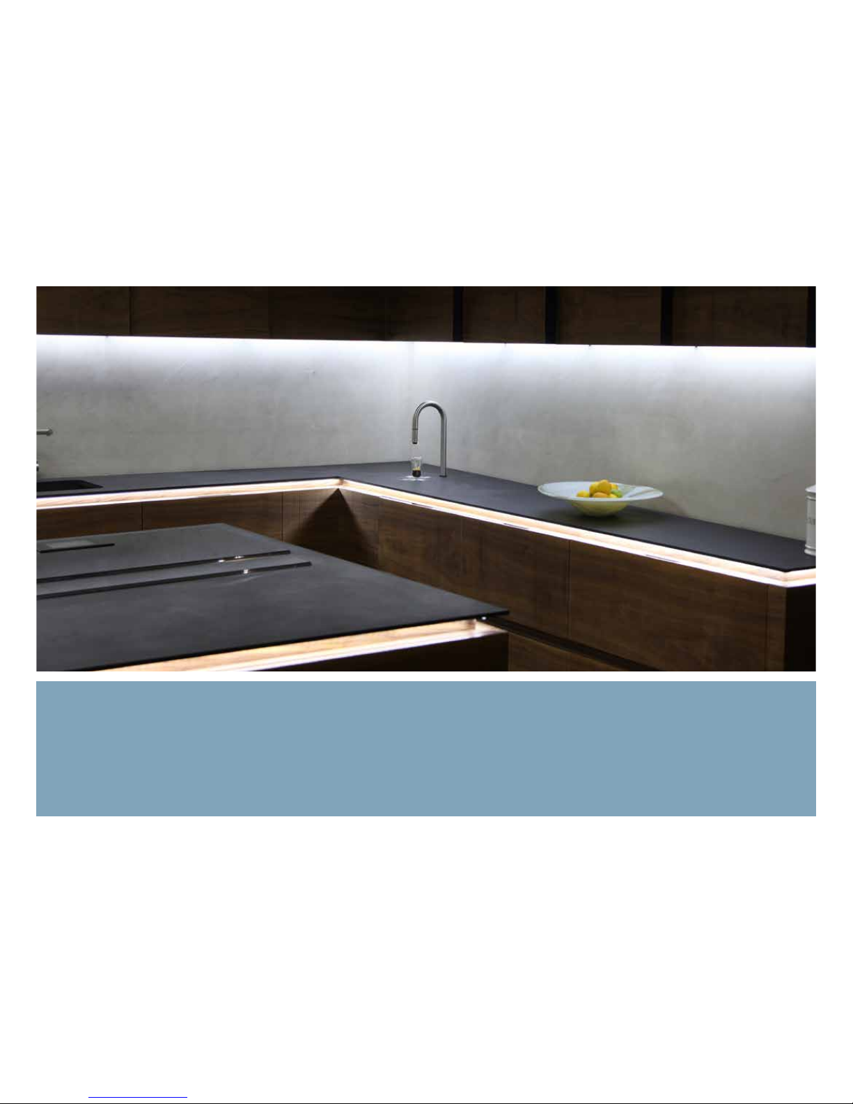
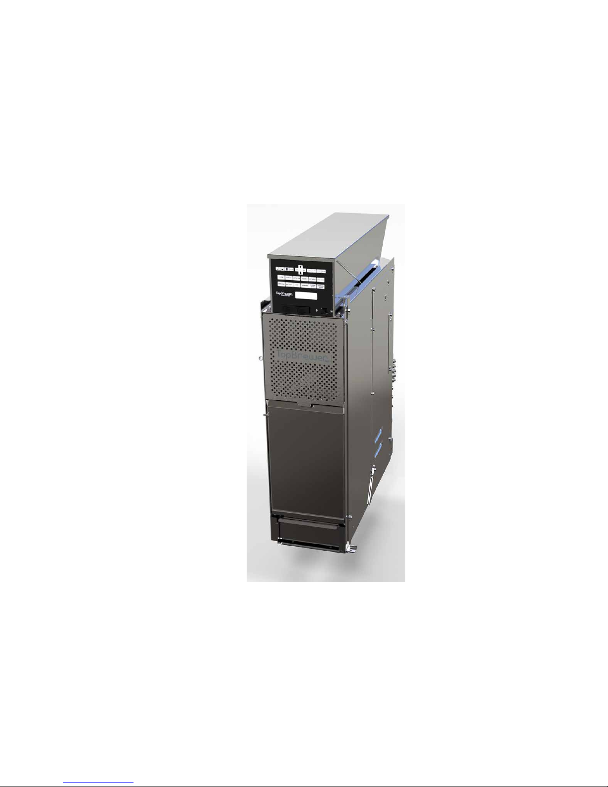
TopBrewer Compact Installation Guide
Aug 12, 2015 Ver. 1.1
Page 2
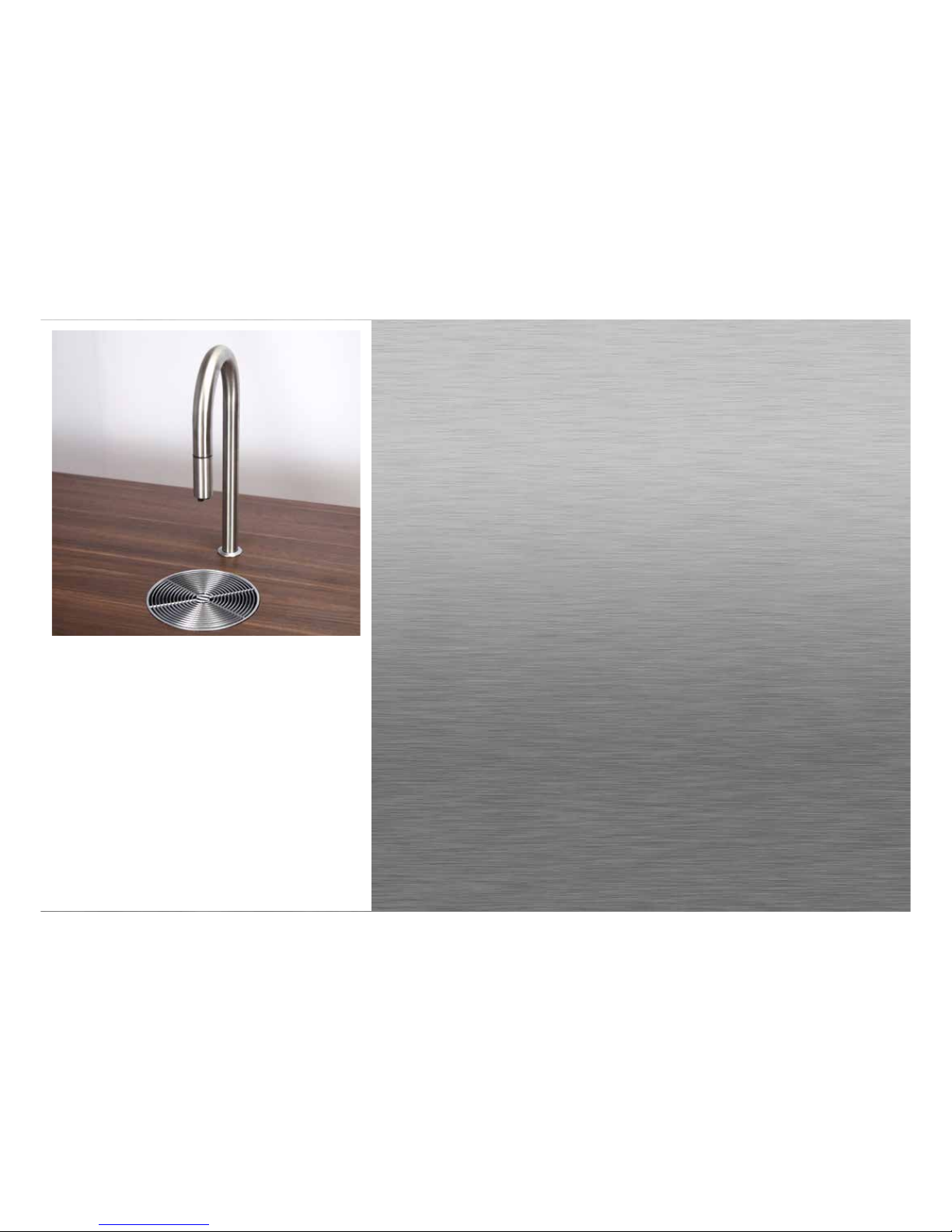
TopBrewer Compact Installation Manual.. Ver 1..0
Installing a TopBrewer can be a fulfilling experience. It’s
like any project, that are taking shape and once done, the
result is mesmerizing.
Still, with the TopBrewer there is a certain degree of unexpected pleasure, when you serve the first piping hot cup of
coee out of the graceful swan neck. The sensation when
the liquid flows and the joy brought to those controlling it
from their phone.
IIf you follow this guide carefully, it will fit beautifully into
your space.
We hope you will enjoy your TopBrewer Experience.
#unboxingmytopbrewer
Page 3

Kind Disclaimer
The TopBrewer is a precision piece of machinery, a fine work of engineering that
has been built to last. Due to the nature of it’s inner workings that are able to
produce a second-to-none drink, installation must be done in line with factory
recommendations in this manual.
We also strongly discourage you from using parts, tubing, fittings and items of
that nature, that are not supplied by TopBrewer.
We also recommend only using TopBrewer certified consumables, such as Coffee (so that we may help you adjust your machine), Water Filters, Co2 bottles
and Cleaning tablets.
Only this way we can ensure that your machine works to the best of it’s ability.
Page 4
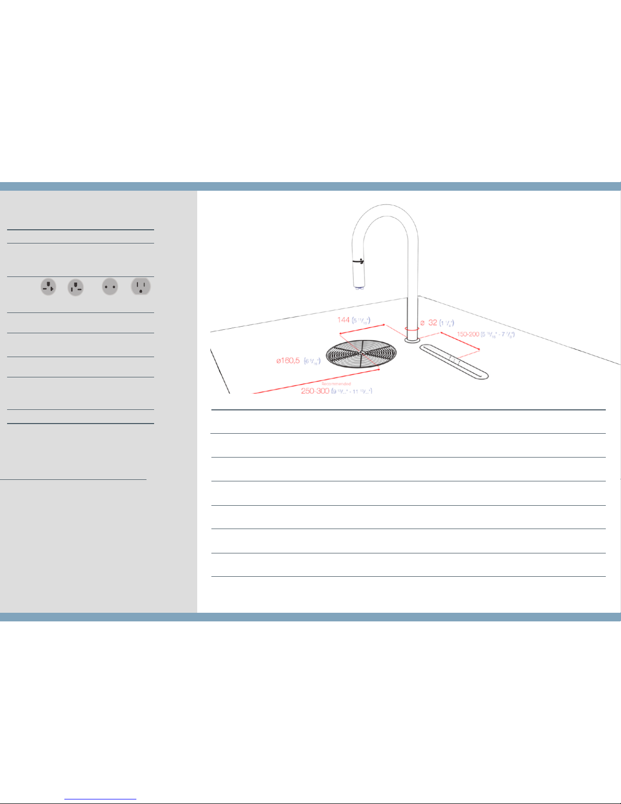
UNIT DETAILS
Installation Dimensions (WxDxH)
Packing Dimensions (WxDxH)
Weight, gross.
Weight, net.
Hopper Capacity
Milk carton size capcitiy (EU/US)
Dreg capacitiy
183 x 510 x 670
7
3
/16” x 20 1/16” x 26 3/8”
300 x 630 x 780
11
13
/16” x 24 13/16” x 30 11/16”
41.0
90.4
39.0
85.9
1.5
3.3
-
60
TopBrewer
Machine
137 x 130 x 267
5
3
/8” x 5 1/8” x 10 1/2”
379 x 284 x 165
14
15
/16” x 11 3/16” x 6 1/2”
3.7
8.15
-
-
-
-
Filter Kit
236 x 560 x 430
9 5/16” x 22 1/16” x 16 15/16”
300 x 615 x 490
11
13
/16” x 24 3/16” x 19 5/16”
27
59.5
25
55,1
-
2 l.
Half Gallon
-
ICE-bank Fridge
* cm / kg / liter - inches / pounds / gallon
TopBrewer Machine
•
TopBrewer, Faucet, mounting bracket, recessed driptray
with grate, quick start guide, cleaning brush, cleaning
tablets
ICE-bank Fridge
•
ICE-bank Fridge, Milk pump system, connections to
TopBrewer, MilkSpear, Co2 Double manometer
Filter Kit
•
2 x TopBrewer Pure 50 filter, 1 x ActiveCoal 10000,
tubes, all fittings and connections, one way safety valve,
mounting diagram.
WHAT’S IN THE BOX?
ACCESSORIES
•
High-Gloss Stainless tap
• Brass tap, polished
• Cobber / Patina tap
• iPad in-counter
• Tabletop
Driptray
• Driptray w/lip
• Active fan kit
* Optional recessed iPad mount
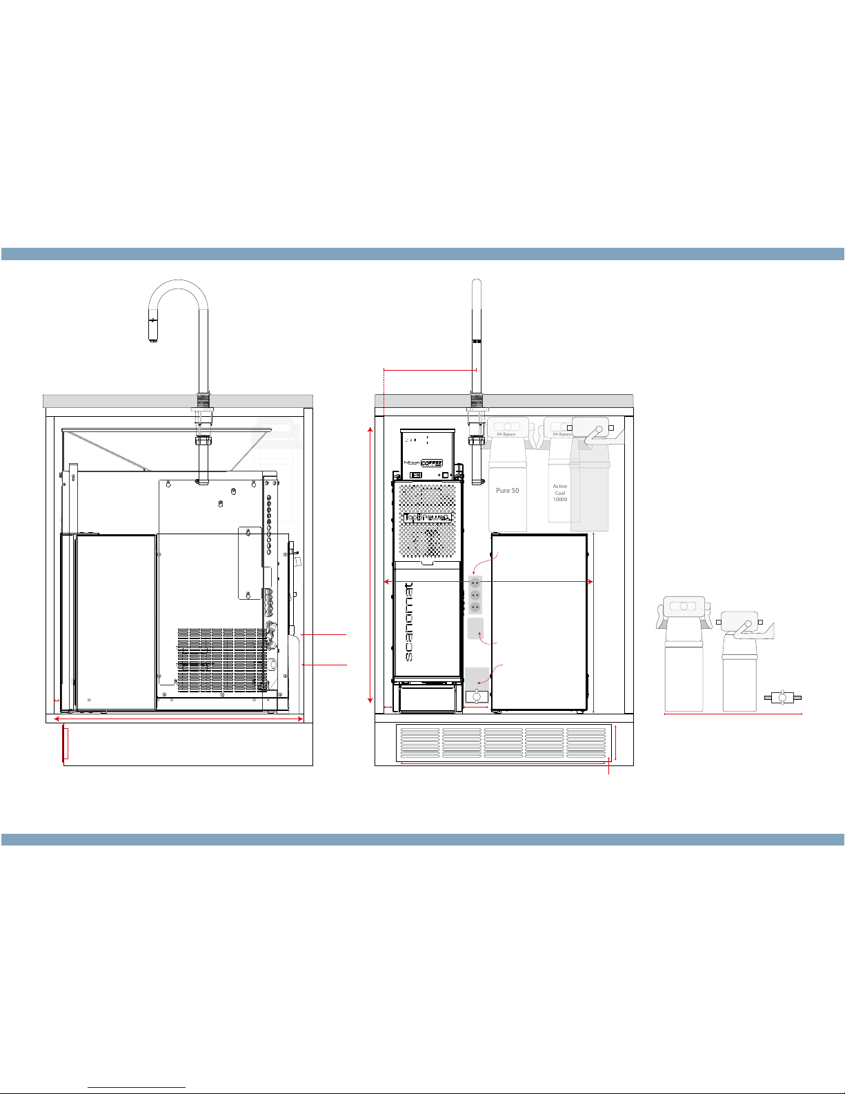
SPACE REQUIREMENTS
Faucet and driptray placement
(per filter, installed)
Plugtype
EU: Local 230V
US: 6-20R / 6-20P
EU: Local 230V
US: Local 110V
Direct Water Connection. Water pressure:
200kPa (2 Bar) - 600 kPa (6 Bar)
Filtration
TopBrewer Pure Filtration kit provides the best
water quality and easy installation
Ventilation
Machine and fridge produces heat,
which needs to be able to exit as per
installation instructions.
See ventilation requirements page 5
Power
208-240V AC,
10/20 Amp 1 phase,
2,3 / 4,6 kW,
50/60hz
TopBrewer
220/110V AC, 4
Amp,
50/60hz
ICE-bank Fridge
Drainage
1 x Waste U-pipe
-
INSTALLATION REQUIREMENTS
Water
*Bold marked items are prefered for installation
Page 5
0% Bypass
Pure 50
Ventilation for air inlet 12 / in (80cm)
25(1”)
10 (
3
/8”)
60 (
2 /” )
Water inlet
Electricity
472(18 /”)
71 (
2 /)
0% Bypass
STRONG YES NO MILD CLEAN STOPON/OFF
COFFEE ESPRESSO CAPPUCCINO COLD MILK HOT WATER
AMERICANO MACCHIATO LATTE WARM MILK
STEAMING
WATER
COLD WATER
SPARKLING
WATER
670 (26
3
/
8
")
Ideal 690 (27
3
/
16
")
238 (9
3
/8")
Shuto valve
Waste U-Pipe
430
(
16 15/16")
AC Power
Hardwired or plugpoint
see specications
560 (22
1
/16")
509 (
201/16")
Alternative placement of shuto valve next to lters
Filters can be mounted in an adjacent cabinet
Active
Coal
10000
Pure 50
0% Bypass
30% Bypass
ICE-Bank Fridge
AC Power
220V Hardwired/Plugpoint
for machine, see spec.
30% Bypass
Pure 50
Active
Coal
10000
Page 6
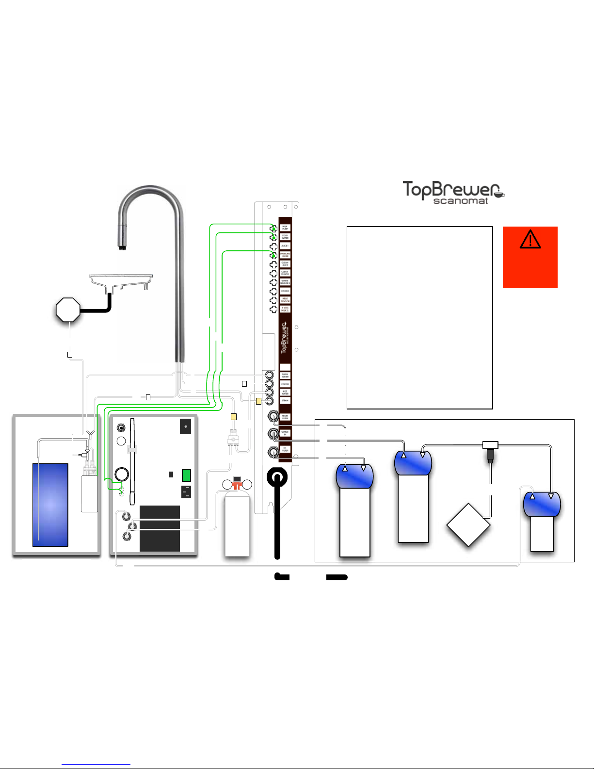
Connection panel
of TopBrewer
Pure
Water
50
0%
2
Pure
Water
50
30%
208-240V AC, 20 amp. (10 amp min.)
1,6 m. / 63" cord length
MAIN
POWER
Compact
3
8
7
9
1
0
12
1
0
4
Hose Connections
1. Flush Water (connected from fridge)
2. Coffee
3. Steam
4. Hot Water
5. Cold / Carbonated Water
6. Milk line (connected from faucet)
7. Steam water out
(going to filter)
8. Main Water inlet
9. Steam water in (coming from filter)
10. Water Inlet (for ICE-bank)
11. Co2 connection hose
12. ICE-bank fill
13. Milk Flush Drain Line
Signal Cables
A. Milk Pump
B. Cold Water Valve
C. Sparkling Water Valve
AC
Filter
0%
5
10
Co2
Rear View
Main
Water
⅜" thread
Connection Diagram with ICE-bank Co2 Fridge
Thermostat
Max
position: 6
11
ICE-bank /
Refrigerator
MILK
6
1
B
A
C
Drain
ATTENTION
Fill ICE-Bank
before use
See Filter Diagram
13
Ver. 1.41, 05/10/14
C
S
W
M
D
Page 7
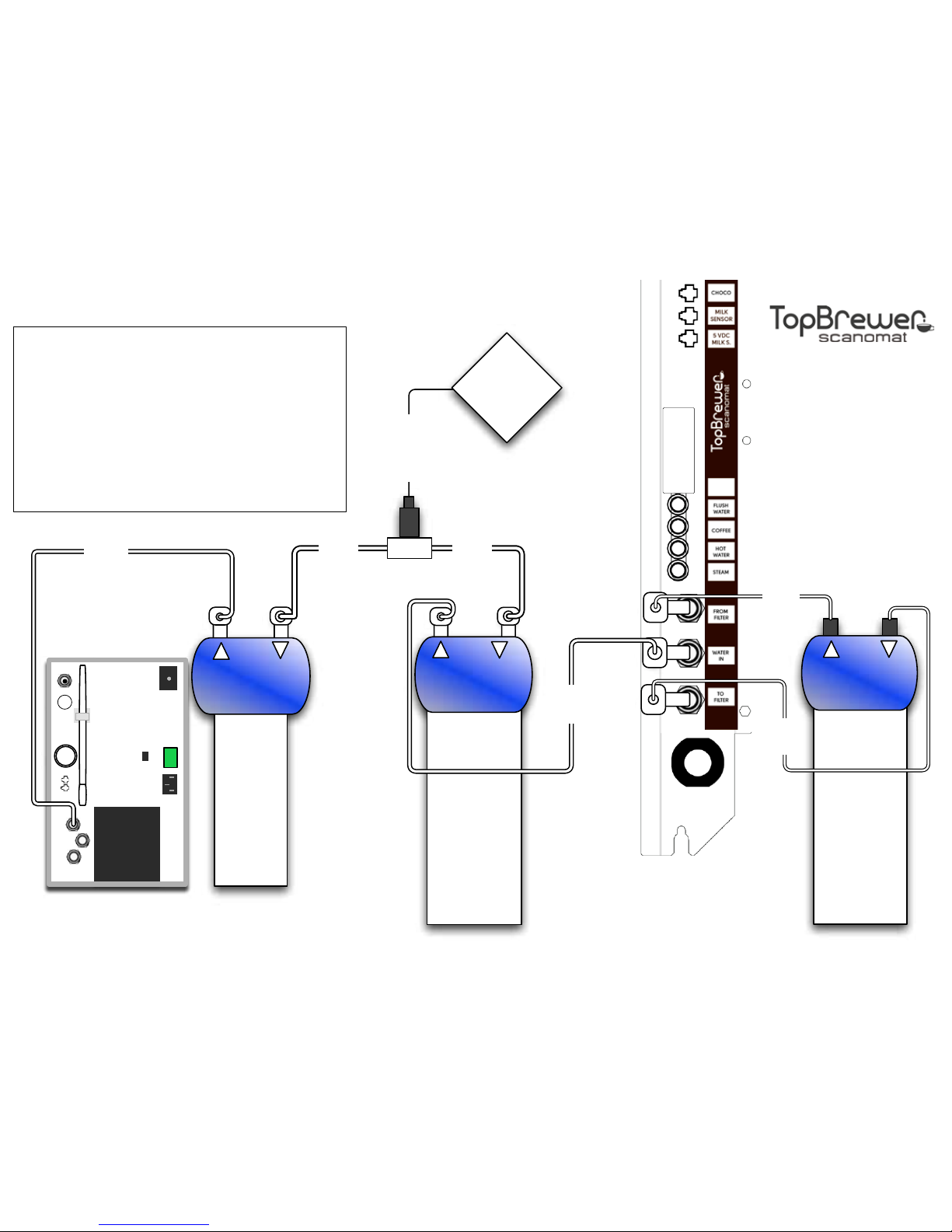
Connection panel of
TopBrewer
1
0
1
0
Pure50
30%
(for main inlet)
8x8
Angle
Fitting
(optional)
8x6
Angle
Fitting
Pure50
0%
(for steamer)
2x 8x4
Straight
Fitting
Main
Water
Hose with ⅜"
female
connector
(not included)
8mm
hose
Filter Starter Kit. Connection Diagram
2 x Pure50 Filters
1 x ActiveCoal 10.000 Filter
2 x 0% filter heads with brackets
1 x 30% filter heads with bracket
3 meter 6mm hose
2,5 meter 4mm hose
1 meter 8 mm hose
1 x Y-piece (6x6x6)
1 x One-way valve &
1 x T-piece (⅜"x8x8)
2 x 8x8 Angle Fitting
2 x 8x6 Angle Fitting
2 x 8x4 Straight Fitting
2 x 6x4 Angle Fitting
3x 6x6 Angle Fitting
Lock Clips
Contents of package
Active
Coal
10.000
0%
8x6 Angle Fitting
8x8
Angle
Fitting
(optional
8mm
hose
4mm
hose
6x6
Angle
Fitting
4mm
hose
6mm
hose
6mm
hose
6x4
Angle
Fitting
One-way valve
& T-Piece
6x4
Angle
Fitting
Compact
Ver. 1.1, 26/08/14
Page 8
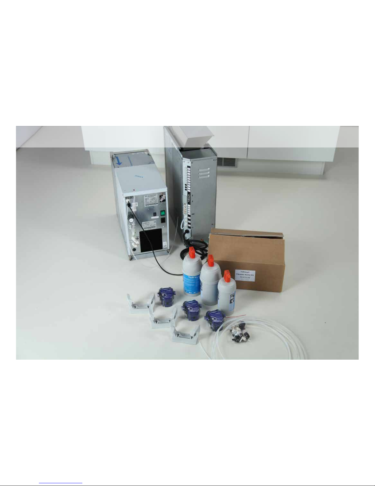
The Anatomy of the system
ICE-Bank Fridge TopBrewer
Filtration Starter Kit
Page 9
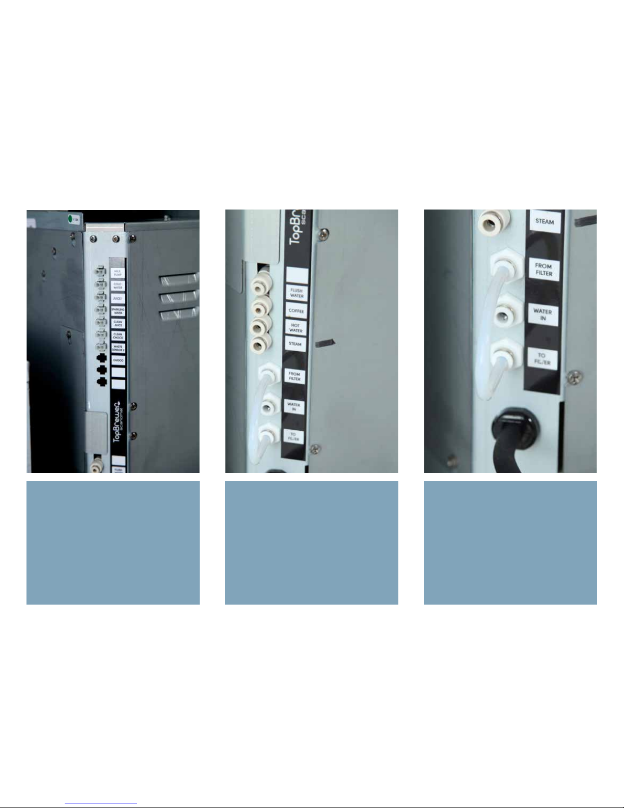
The top of the connection panel, which
you will find on the back of the TopBrewer, is the range of features modules that can be added to the machine
currently and in the feature. The TopBrewer system is clever and expandable. This manual concentrates only on
the “Milk Pump” coming from the fridge
and the sparkling and cold water valves.
A step further down is the quick-fit connections for the hoses. Three of these
goes directly into the faucet, with “Flush
Water” being the exception, going from
the machine into the fridge. (see diagram on page XXXXX)
Lowest on the panel is the Main “Water
In” (coming from the 30% bypass filter)
as well as two additional connections
going to a dedicated steam filter. This
to ensure a 100% filtration of the water
dedicated to the steamer, preventing
scale build.
Also here main AC Power cable.
Page 10
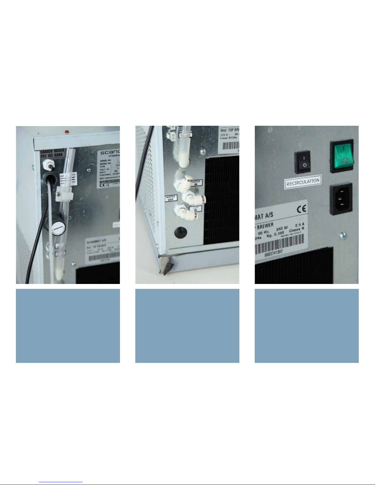
On the top left side you have an inlet to
fill the ICE-Bank with water. This must be
done prior to powering it up! The transparent tube reads the fill level.
The dial is a pressure regulator for the
inlet water, which should only be adjusted if the water is not flowing at a
speed, that fills the glass to the level
specified in the app.
The two Molex plugs are for Cold and
Sparkling water, plugged into the TopBrewer. These signal cables control the
valves inside the fridge individually.
The quick-fit connectors below are for
Main “Water In” from the AC Filter, Water out and CO2.
The main power switch (Green) as well
as the AC power.
The recirculation switch is to remain on
always, controlling the pump that circulates the cooling water that cools the
Fridge-space.
Page 11
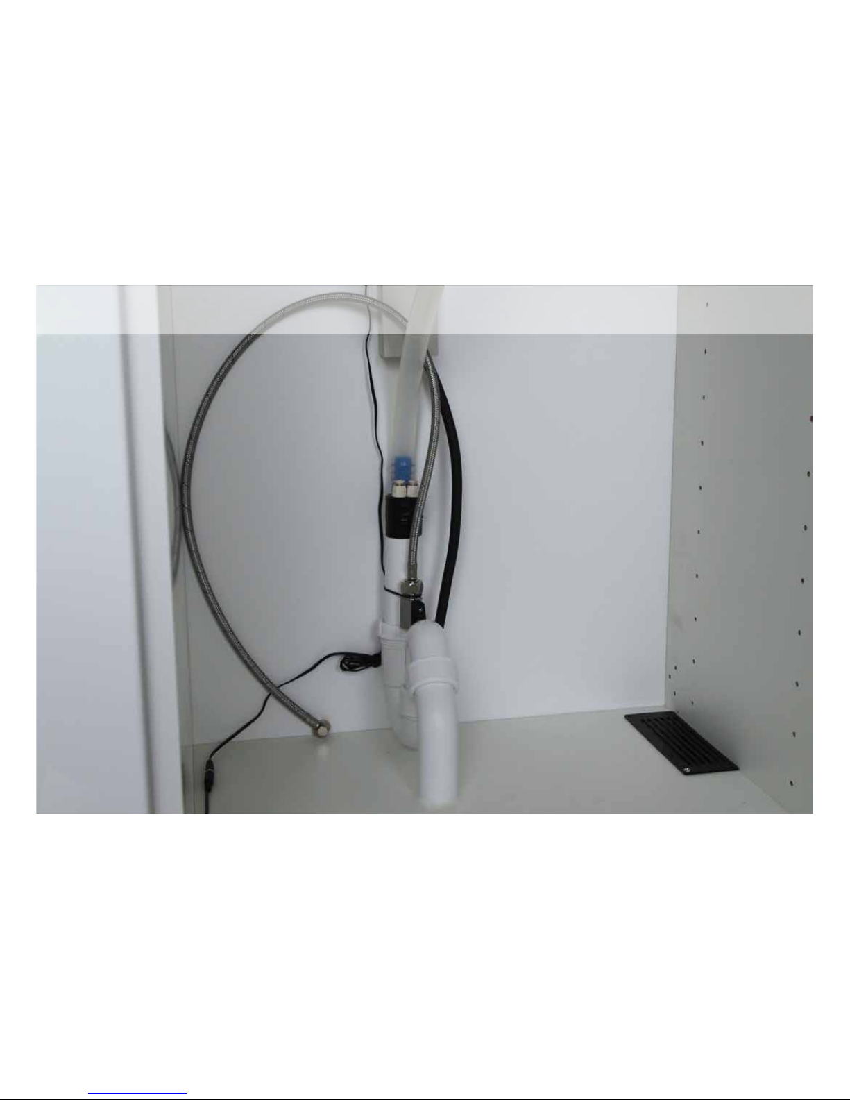
Preparing your space
Page 12

CARPENTER
Page 13
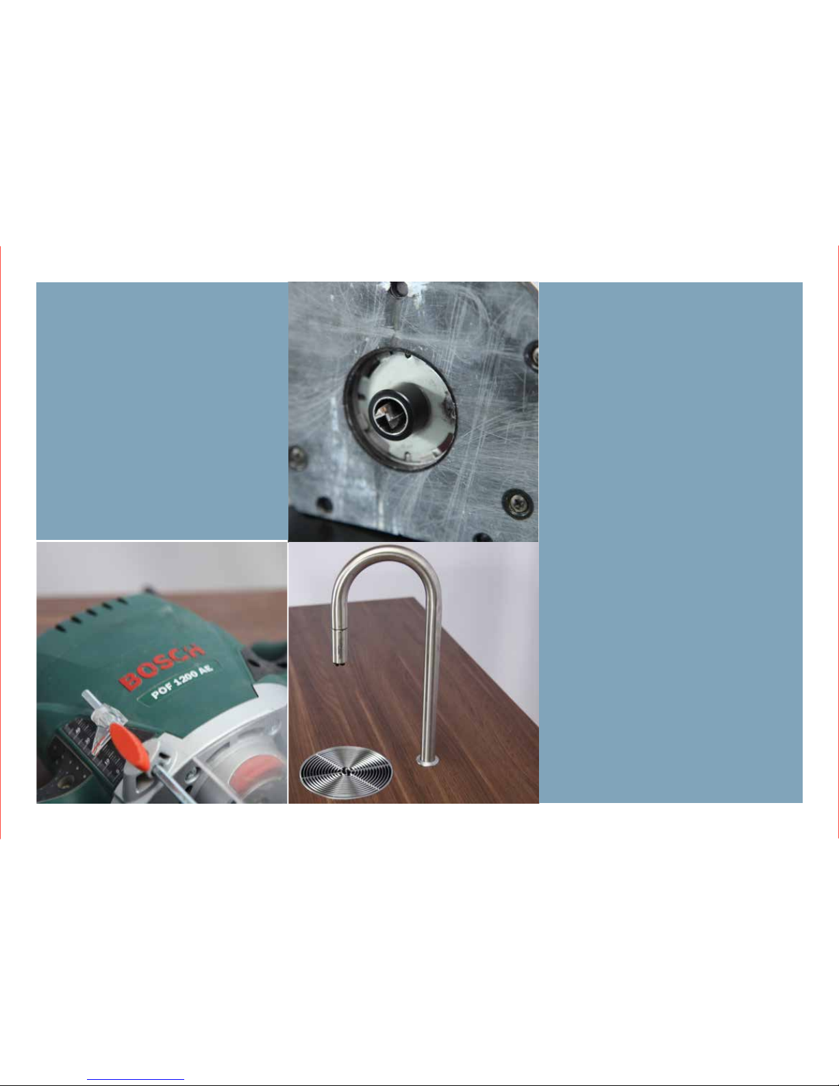
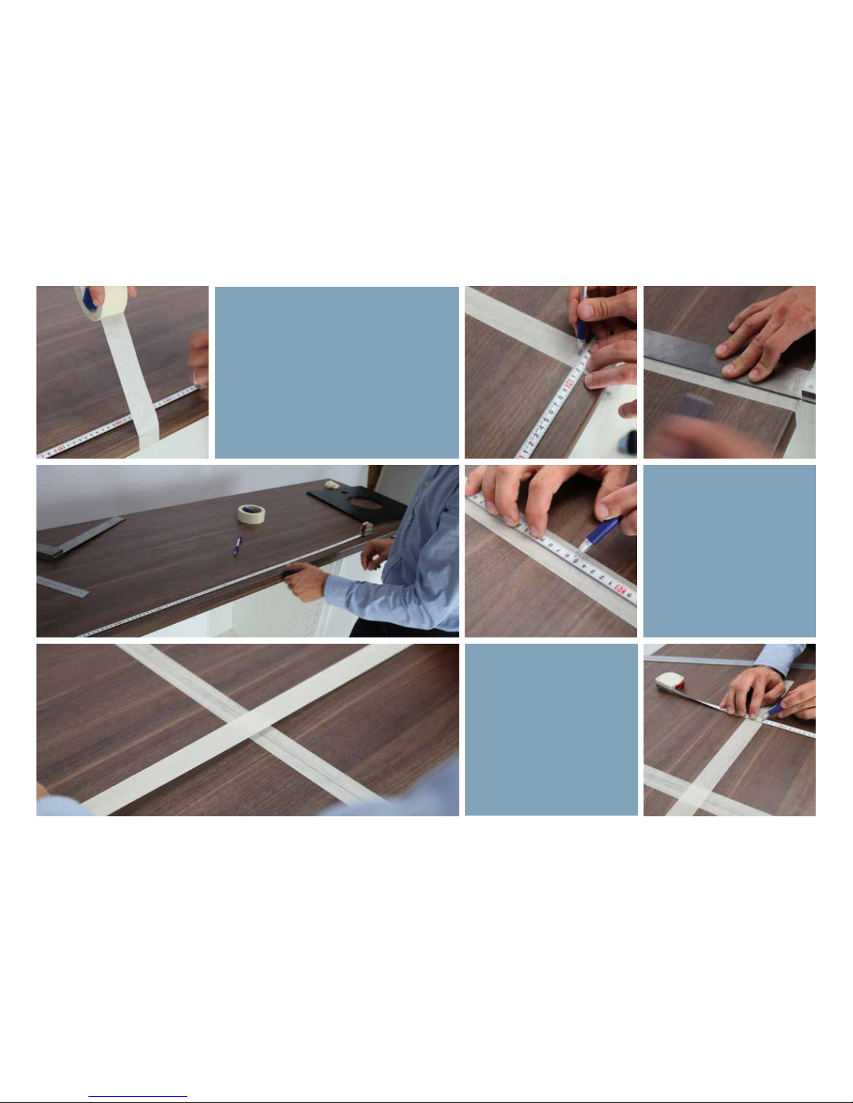
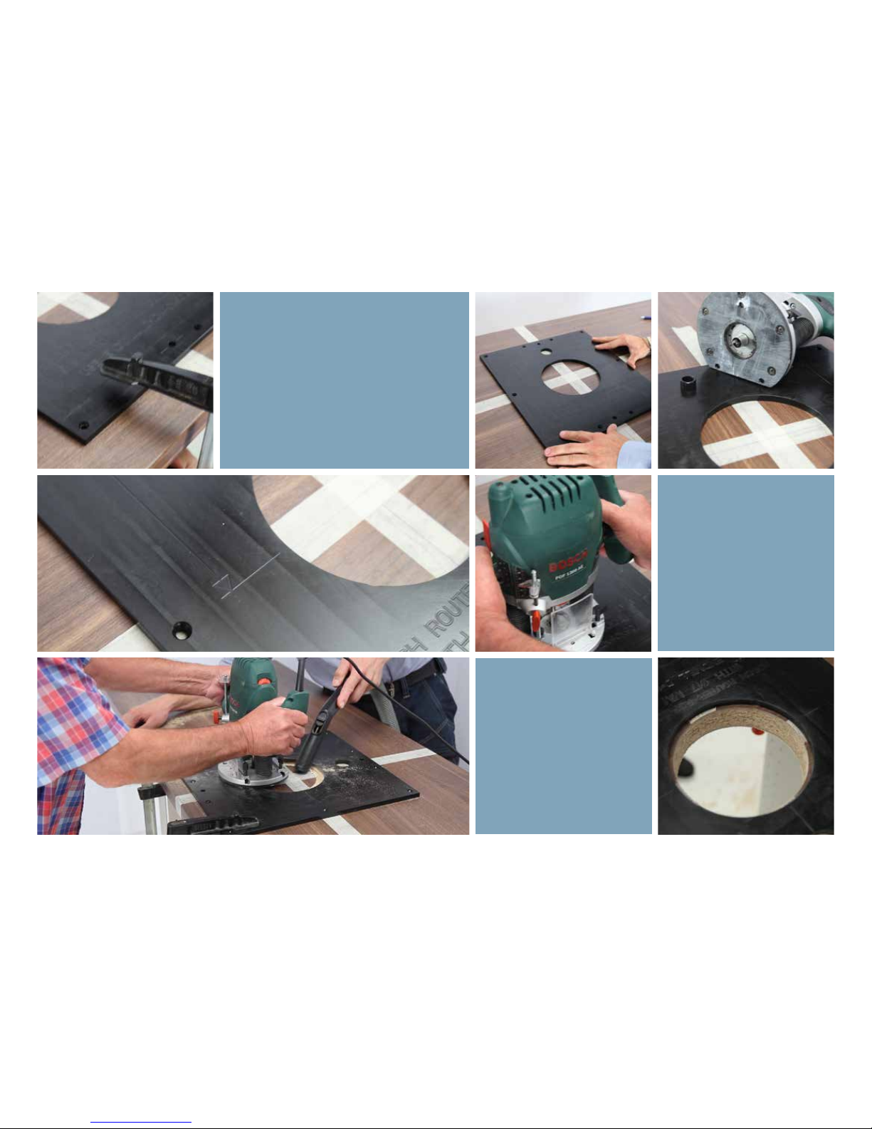
You will need:
- Cut out template
- Bosch PDF 1200 AE Router or similar
- Clamps
Readying your tabletop
Page 14
Page 15
Page 16
Page 17
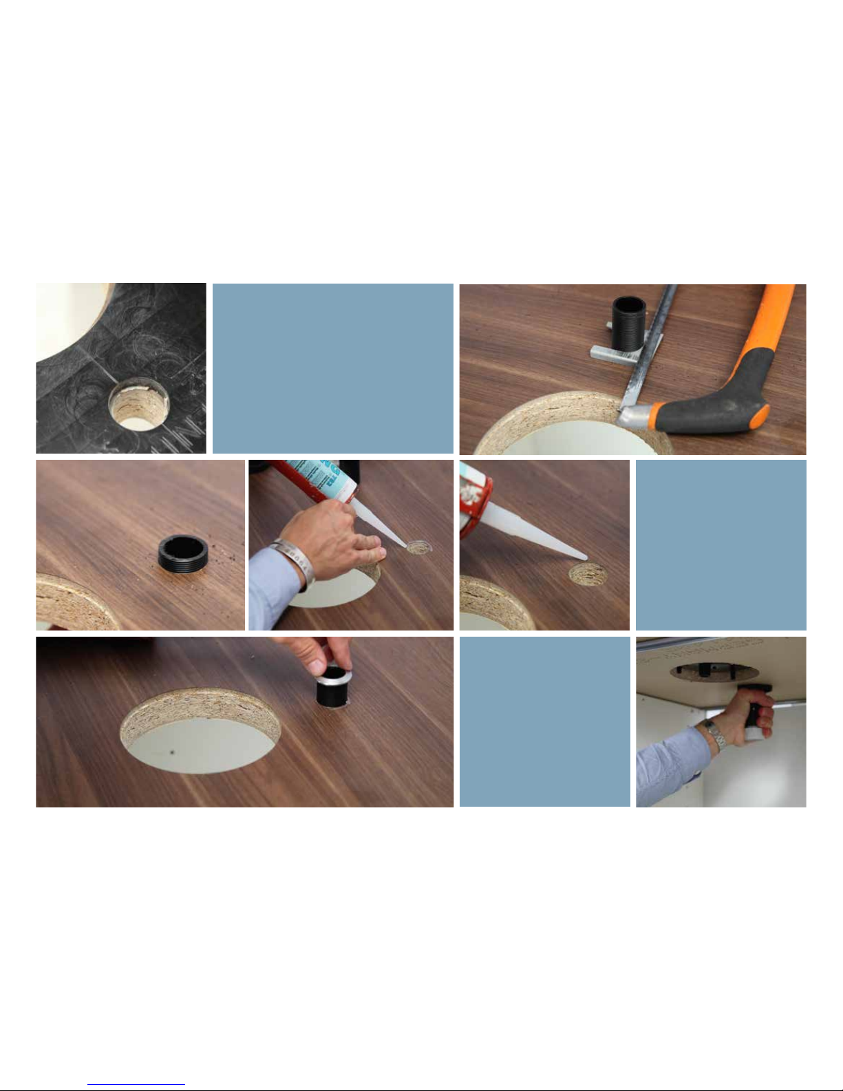
When the hole for the faucet is done,
the threaded sleeve is inserted from
the bottom, and using the accompanied guide, it’s cut to length to allow for
enough thread to pass through to reach
the bracket that holds the faucet.
Use a silicone adhesive to
make a proper seal. It’s recommend also to silicone open
pours in the wood.
The sleeve is now inserted
from the top as shown and
the bracket is fitted from
below. Make sure to tighten it
properly.
Page 18

Use a silicone adhesive to make a
proper seal. It’s recommend also to
silicone open pours in the wood.
Insert the drip tray so that the drain
outlet is aligned with the faucet
sleeve.
Page 19
0% Bypass
Pure 50
25(1”)
10 (
3
/8”)
60 (
2 /” )
Water inlet
Electricity
472(18 /”)
71 (
2 /)
0% Bypass
STRONG YES NO MILD CLEAN STOP ON/OFF
COFFEE ESPRESSO CAPPUCCINO COLD MILK HOT WATER
AMERICANO MACCHIATO LATTE WARM MILK
STEAMING
WATER
COLD WATER
SPARKLING
WATER
670 (26
3
/
8
")
Ideal 690 (27
3
/
16
")
238 (9
3
/8")
Shuto valve
Waste U-Pipe
430
(
16 15/16")
AC Power
Hardwired or plugpoint
see specications
560 (22
1
/16")
Alternative placement of shuto valve next to lters
Filters can be mounted in an adjacent cabinet
Active
Coal
10000
Pure 50
0% Bypass
30% Bypass
ICE-Bank Fridge
AC Power
220V Hardwired/Plugpoint
for machine, see spec.
30% Bypass
Pure 50
Active
Coal
10000
509 (20
1
/16") Total width
iPad
SPACE REQUIREMENTS
Page 20
Page 21
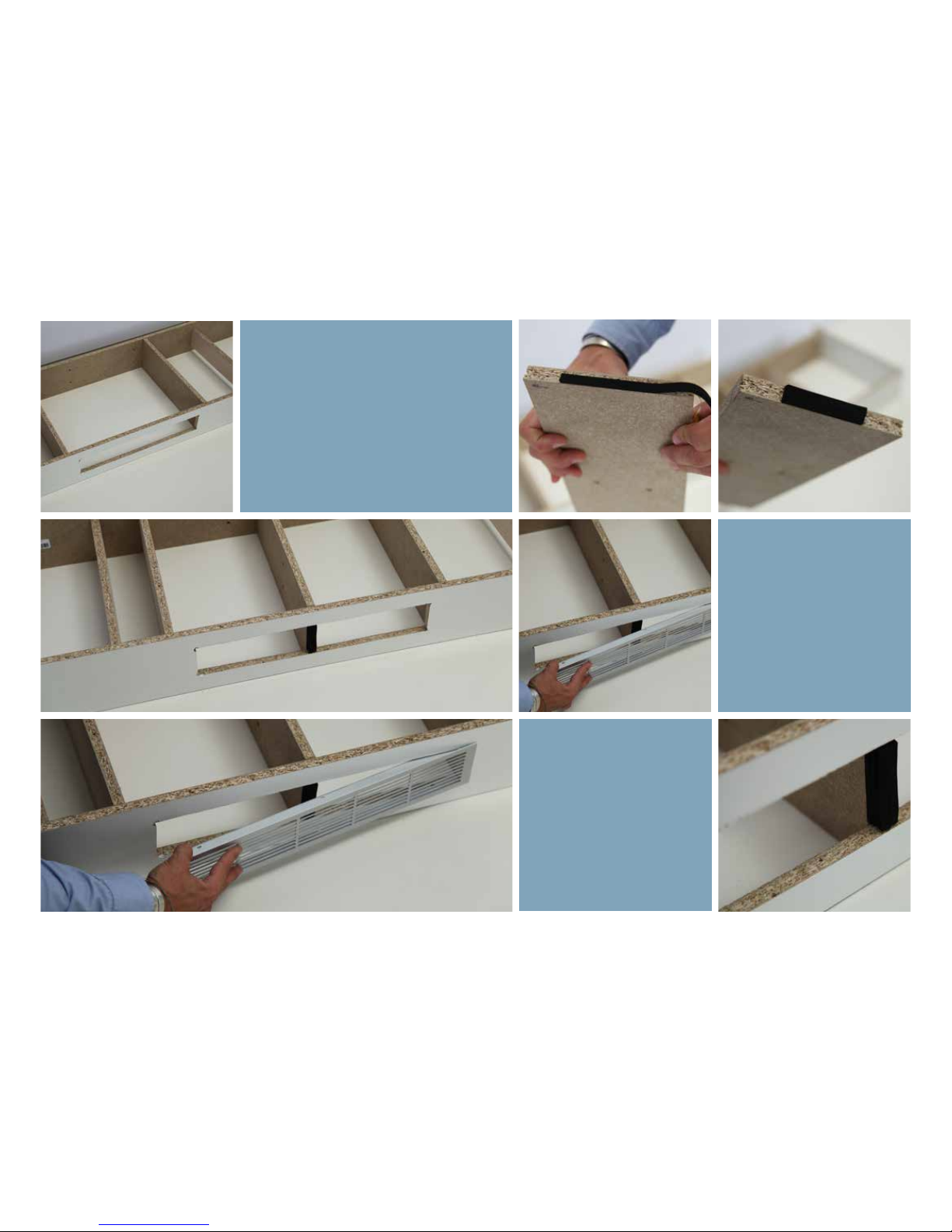
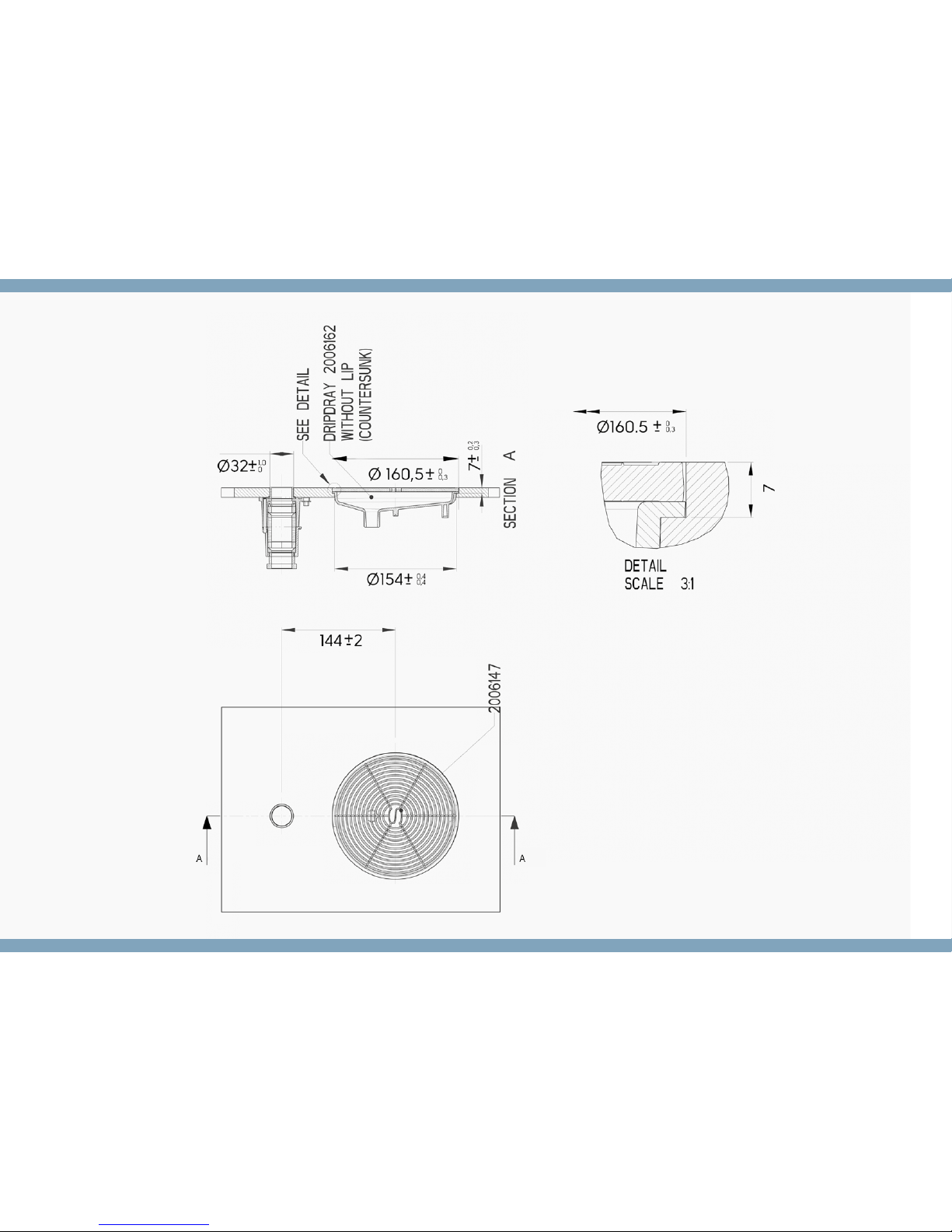
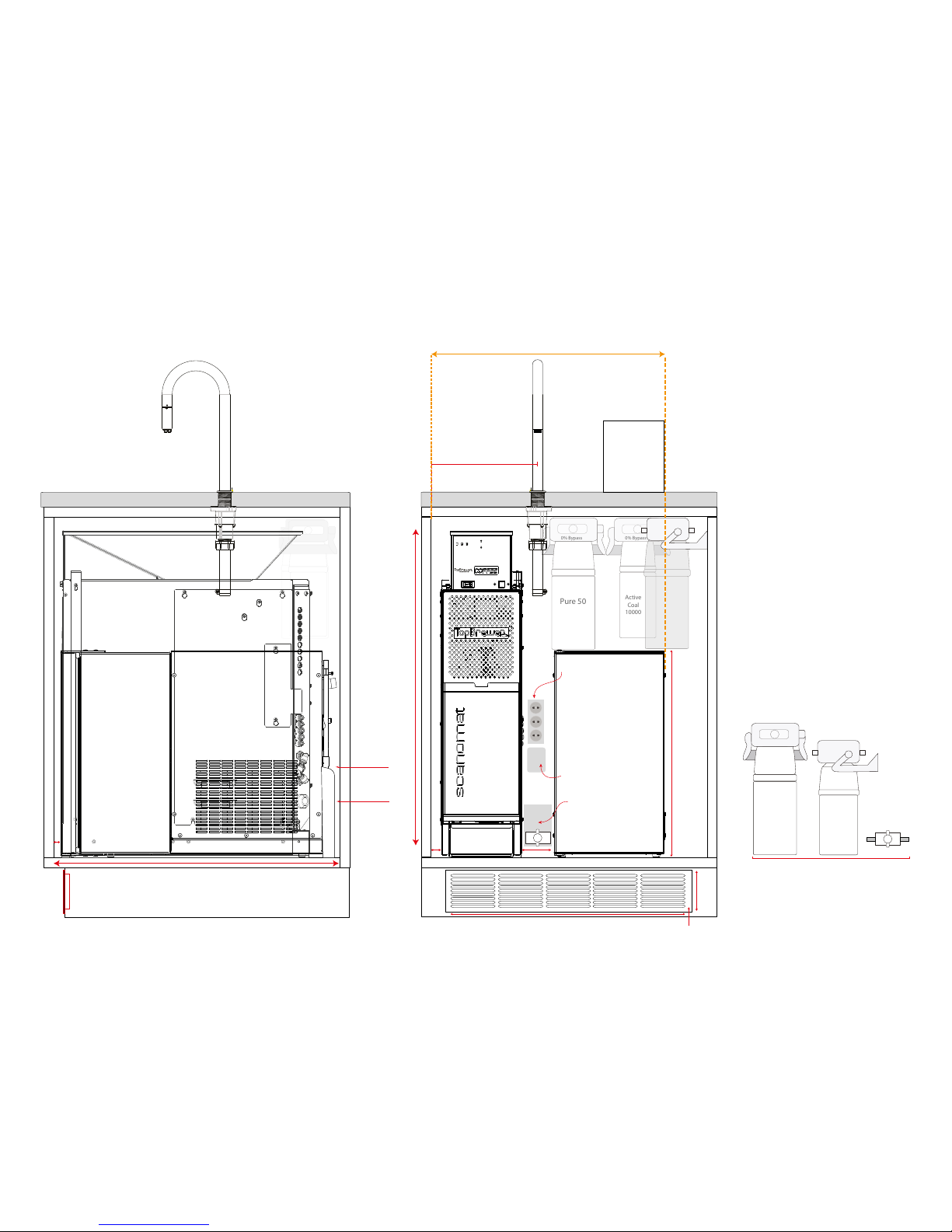
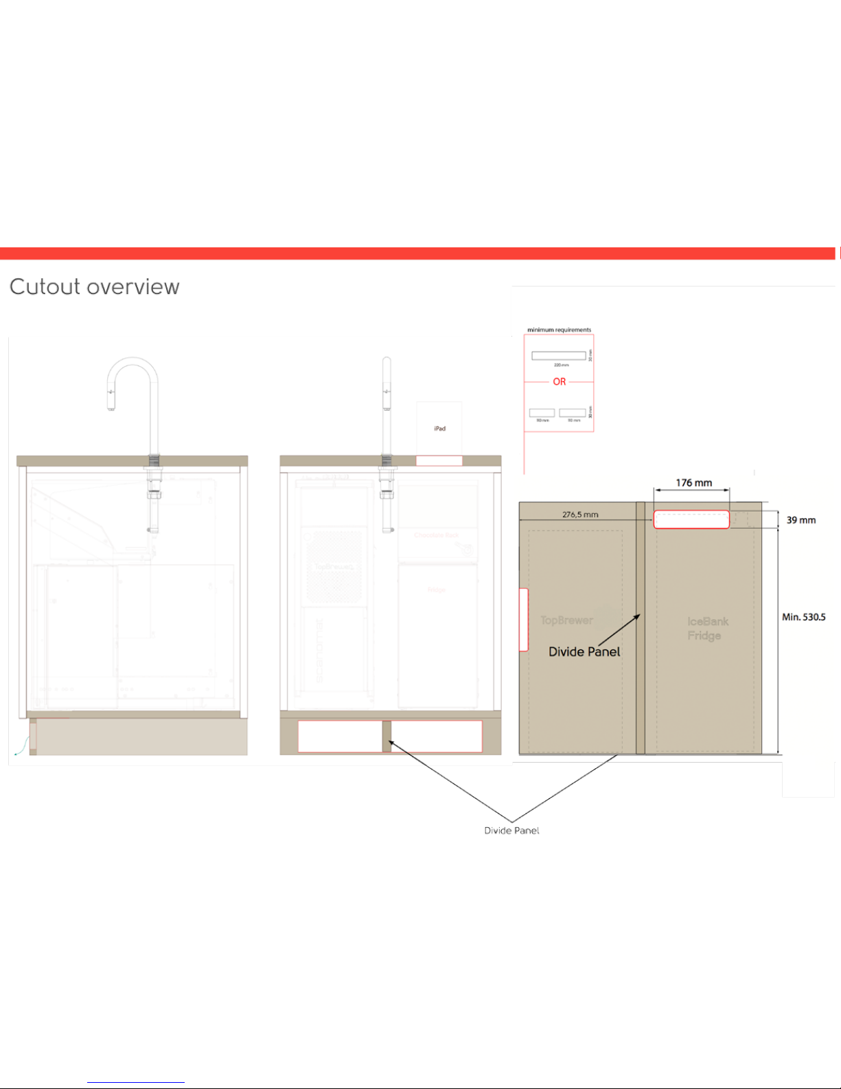
Do cut-outs as outlined in the drawing.
It’s import to follow exactly, as the the
base is used as a ventilation chamber to
allow fresh air in and hot exhaust air out.
Page 22
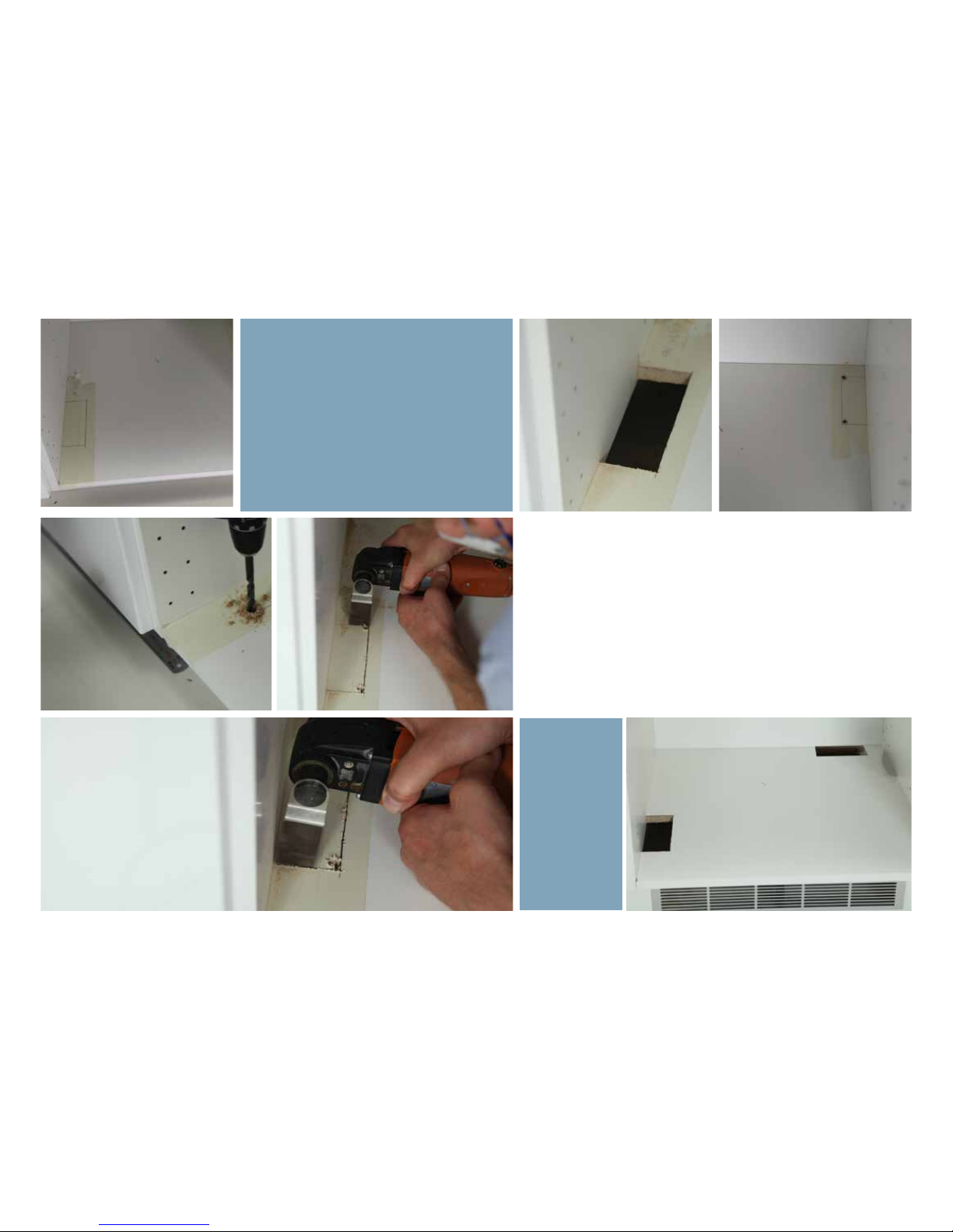
The hole in the far right of the cabinet is
for the fridge - so the placement of the
fridge is decided by this cut-out.
Use a
Fein-cutter or
similar
Page 23

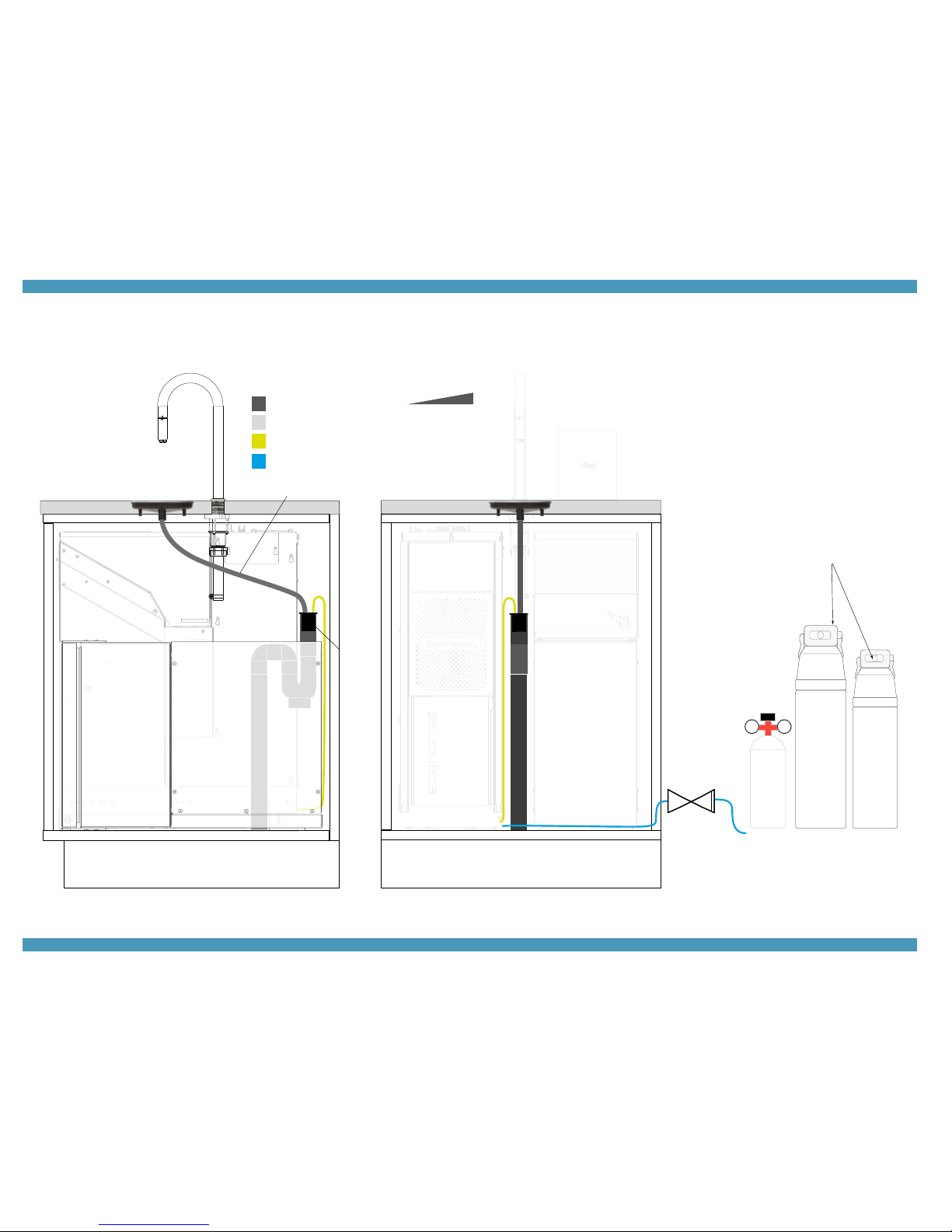
PLUMBING
Page 24
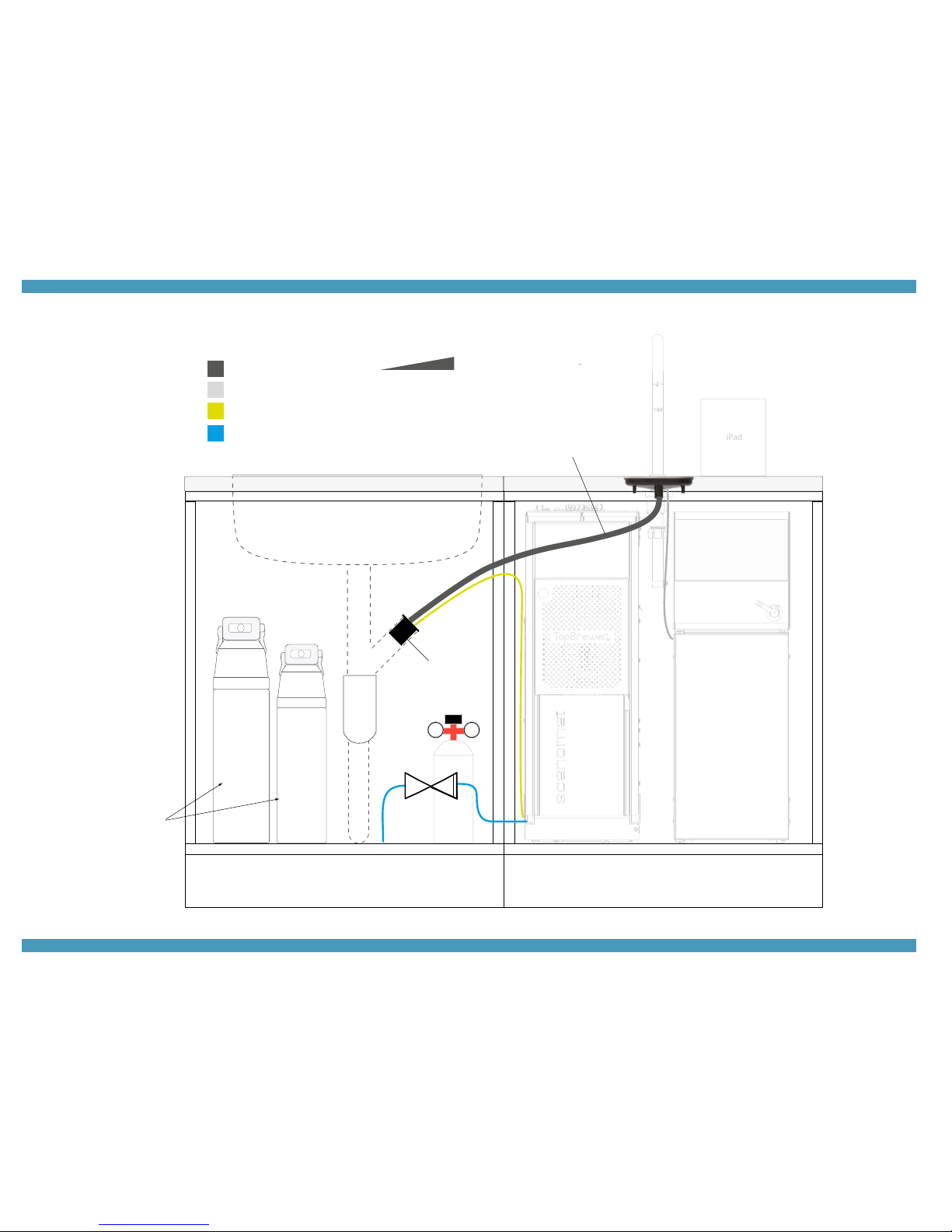
C150
C300
iPad
Drainline from driptray
Drainpump from machine
Fridge waste water
Main Water w/ shuto valve
Filters
Drain plug provided
Pipe size Ø40
Drainline Ø18mm
125 mm
464 mm
417 mm
119 mm
1 m
5 cm
CO2
Plumbing option 1
Optional Co2 bottle placement.
(if applicaple). Must be standing
upright, max pressure setting 3 bar.
Page 25
iPad
C150
C300
Filters
125 mm
464 mm
417 mm
119 mm
CO2
Drainline from driptray
Drainpump from machine
Fridge waste water
Main Water w/ shuto valve
1 m
5 cm
Drain plug provided
Pipe size Ø40
Drainline Ø18mm
Plumbing option 2
Filters can be placed in an adjacent cabinet. The
shuto valve is advised to be installed along the
filters, also obeying local rules and regulations. Co2
canister (is applicable) must be standing upright.
Page 26
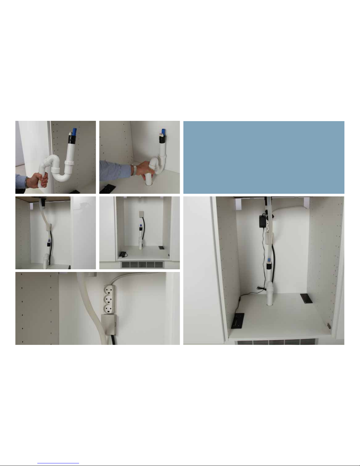
Drain can be positioned either like shown
in the center of the cabinet in between
the machine and fridge.
Electrics can also be mounted in the
top-right corner of the cabinet, when this
space is not reserved for filters.
Page 27
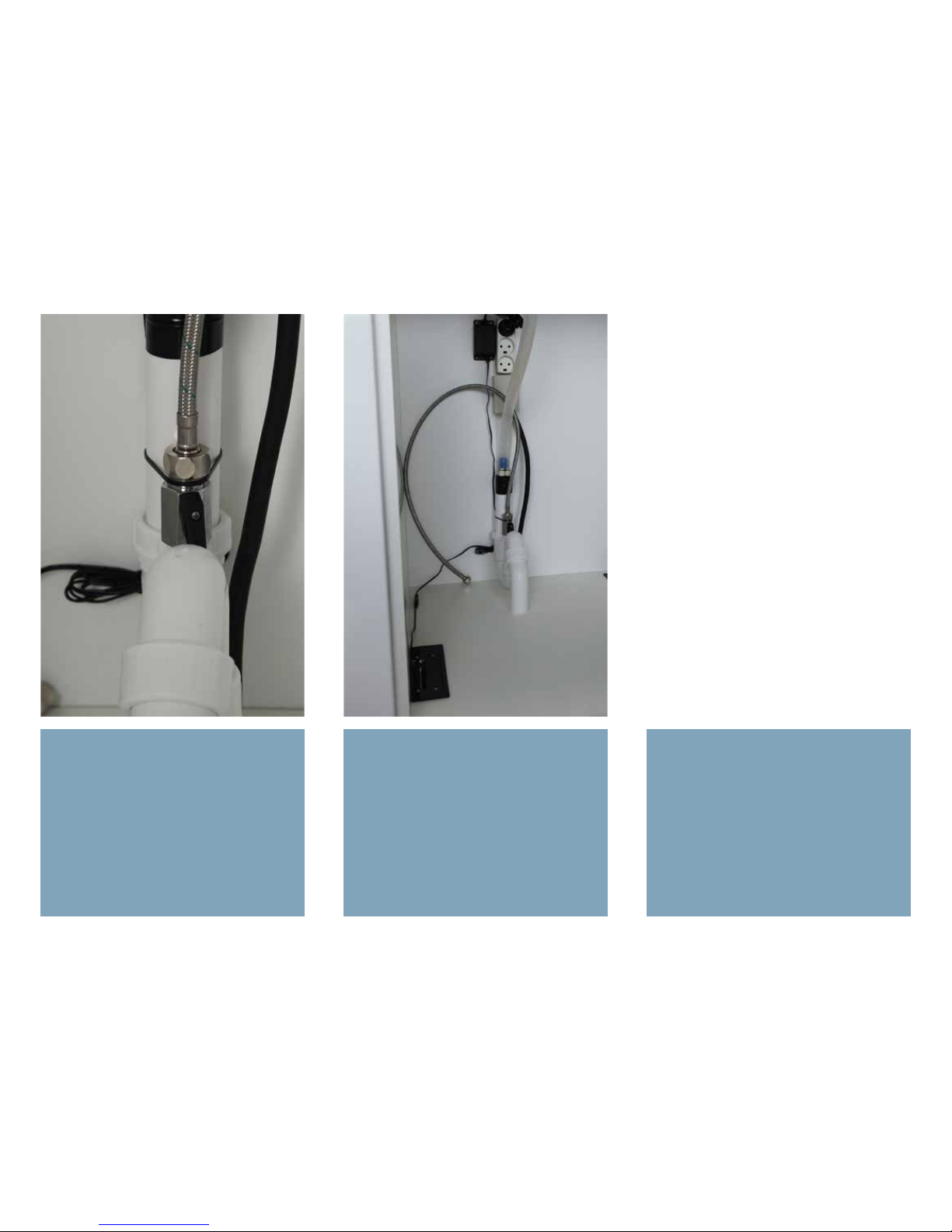
The machine is delivered with a 3/8
inch male check-valve. Not supplied is
a country specific connection hose and
shuto valve.
An overview on how the installation
could end up looking like.
Page 28
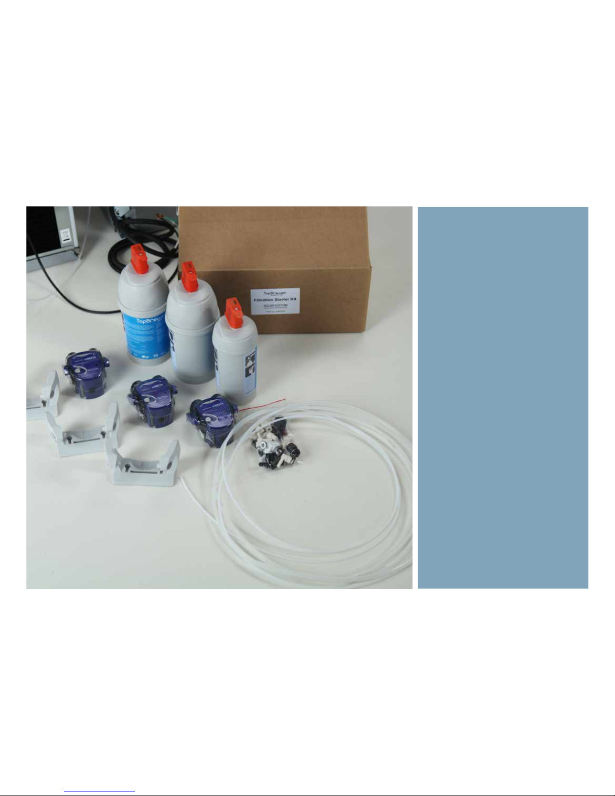
Filtration starter kit
The kit consists of:
2 x Pure50 Filters
1 x ActiveCoal 10.000 Filter
2 x 0% filter heads with brackets
1 x 30% filter heads with bracket
3 meter 6mm hose
2,5 meter 4mm hose
1 meter 8 mm hose
1 x Y-piece (6x6x6)
1 x One-way valve &
1 x T-piece (⅜”x8x8)
2 x 8x8 Angle Fitting
2 x 8x6 Angle Fitting
2 x 8x4 Straight Fitting
2 x 6x4 Angle Fitting
3x 6x6 Angle Fitting
Lock Clips
Note: This is a proposed setup. Installing
the filters in adjacent cabinets is also an
options, as long as supply lines are able
to move freely and not obstructing the
sliding motion of the machine. Leave
also lenth enough for the fridge to be
pulled out for service.
Page 29
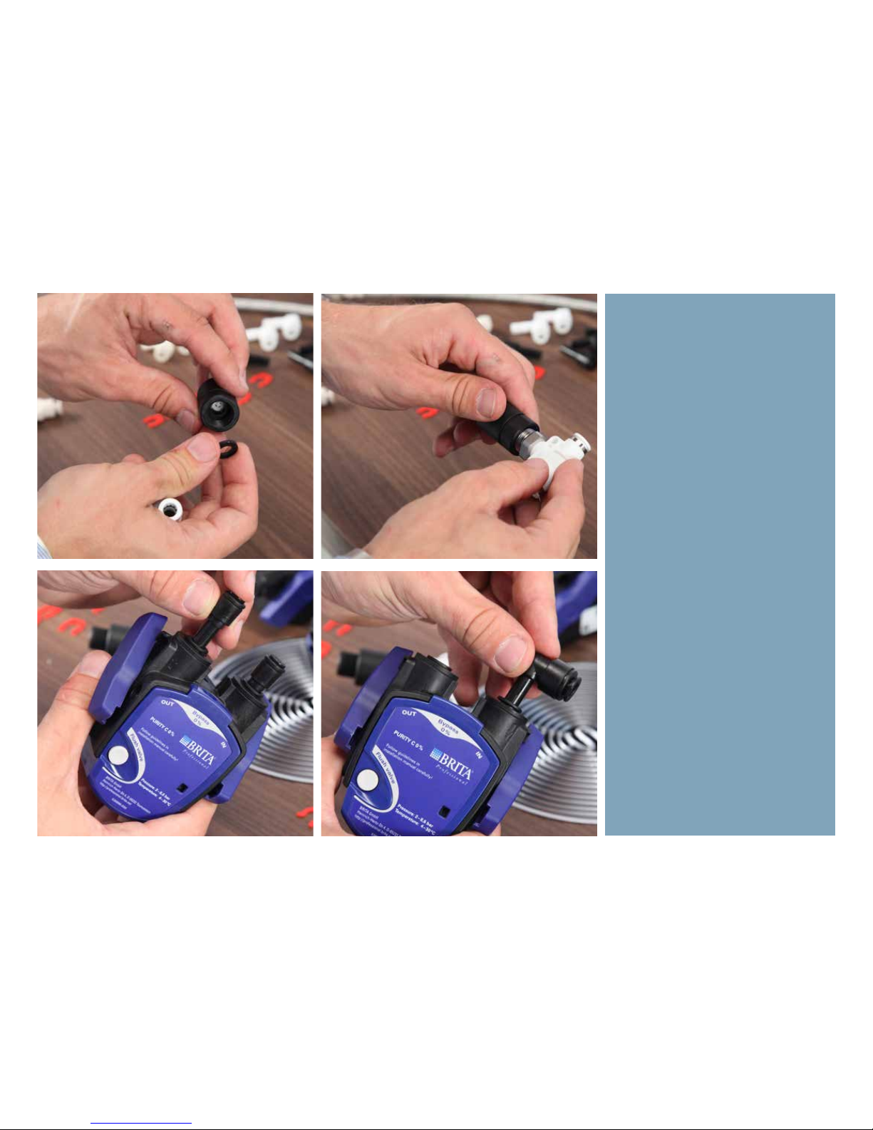
First, fit the O-ring as shown inthe
the checkvalve and insert the white
T-piece and tighten.
The first 0% head (see label on top)
is fitted with the two straight fittings
(4mm) as shown.
The second 0% head is fitted with first
a 8mm angle fitting on the “in” side as
shown.
Page 30
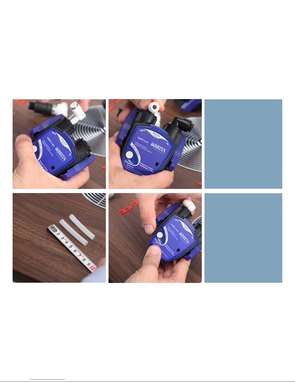
And next a 6mm angle fitting on the
“out” side.
Cut two pieces of 6mm hose to
length, at 6 cm
Page 31
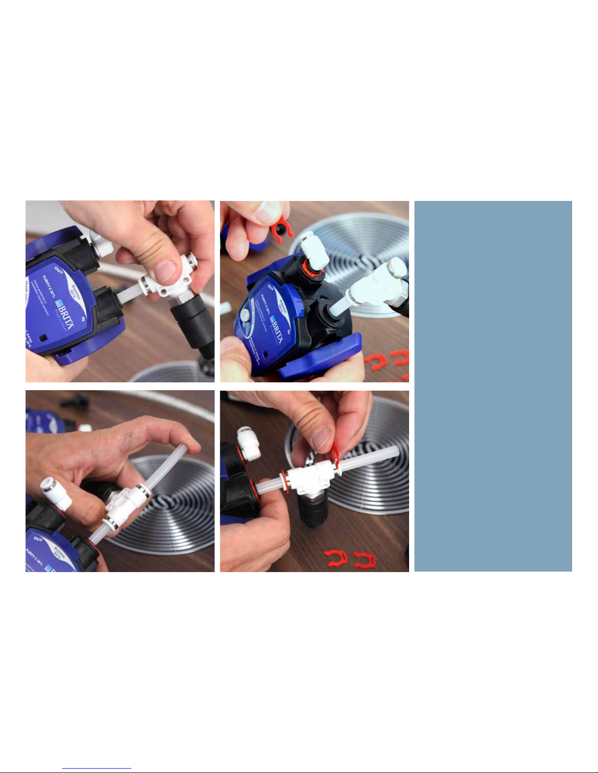
Fit the T-piece we assembled before
on the “in” side of the 30% head. The
T-piece is used to supply main water
to the machine (through the 30%
head) and also water to the fridge,
through the 0% head.
Fit the other piece of hose to the other side of the T-piece and secure with
lock clips.
Page 32

Fit the heads onto the filters. Ensure (above) to extract the small venthose as shown first.
30% head fits: Pure 50
0% head (with straight fittings) fits: Pure 50 filter
0% head (with angle fittings) fits: ActiveCoal 10.000 filter
As shown to the right here, a proposed configuration puts the 30% filter
and the 0% with the angle fittings next to eachother.
Page 33
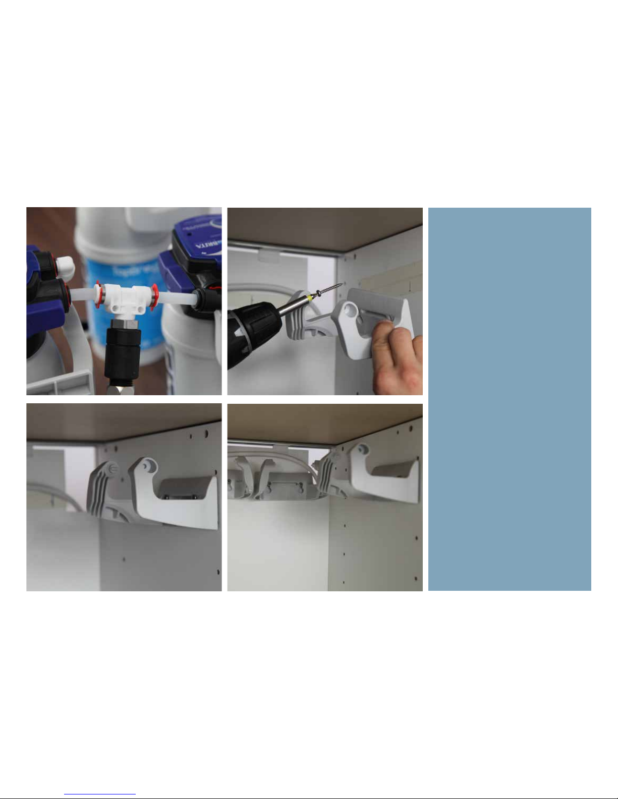
Conect the two filters like shown using the T-piece, so create a “corner”.
Next, place the brackets accordingly
inside the cabinet.
Page 34
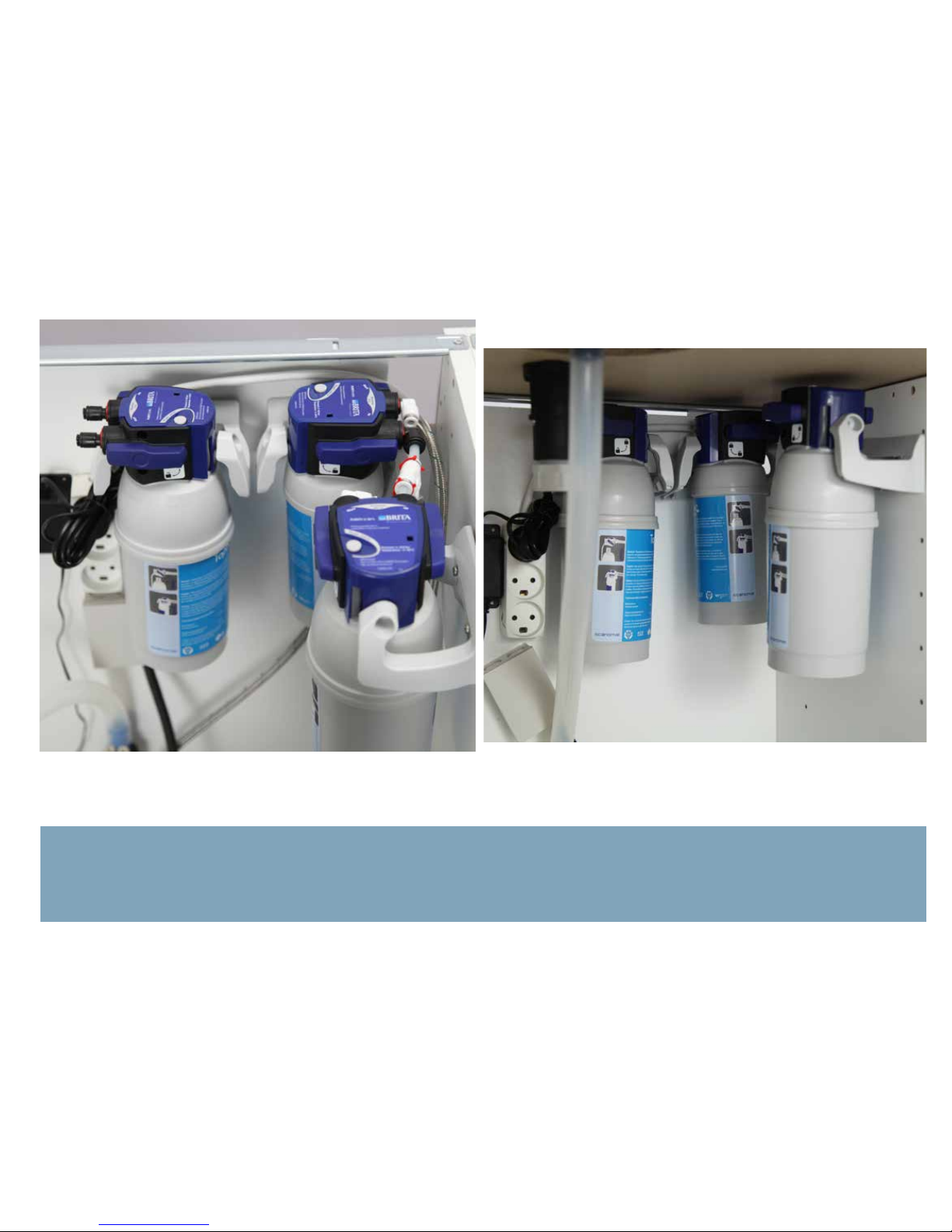
The last filter (with the straight fittings) shall always be placed fairly close to the machine, allowing the two 4mm hoses to move freely, when
pulling the machine in and out.
Page 35
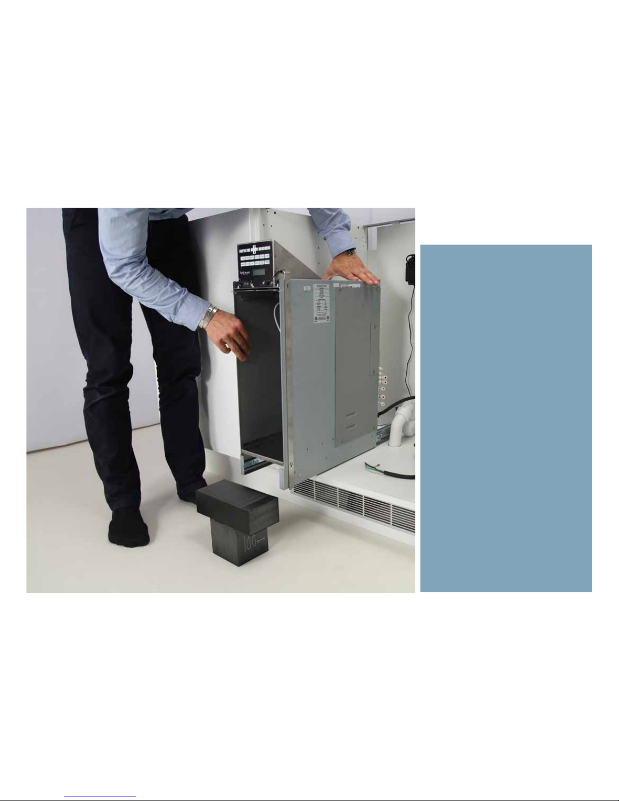
Installing the TopBrewer
Page 36
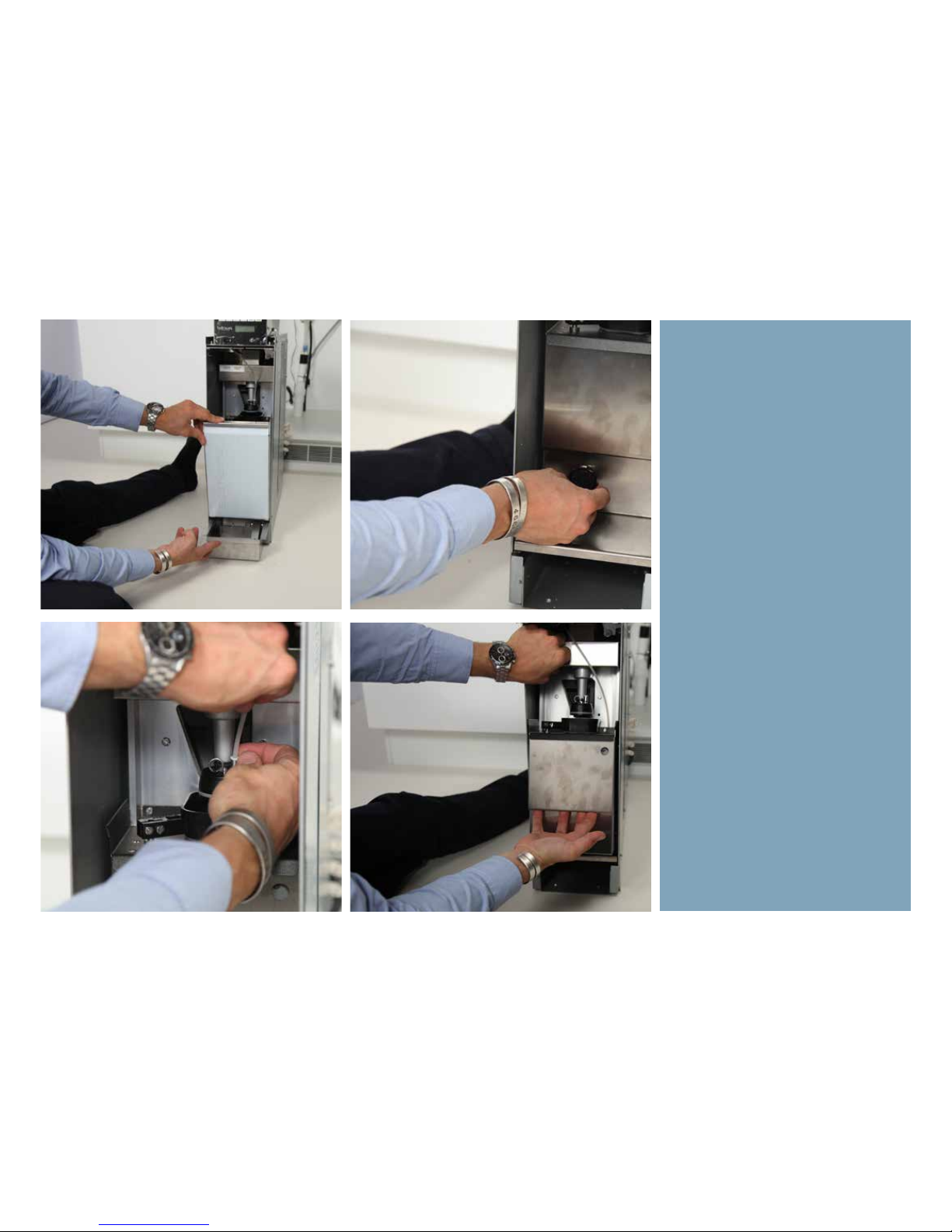
Remove excess wait like the dreg bin,
waste tray and brewer to easy handling.
Page 37
Remove also the bean canister.
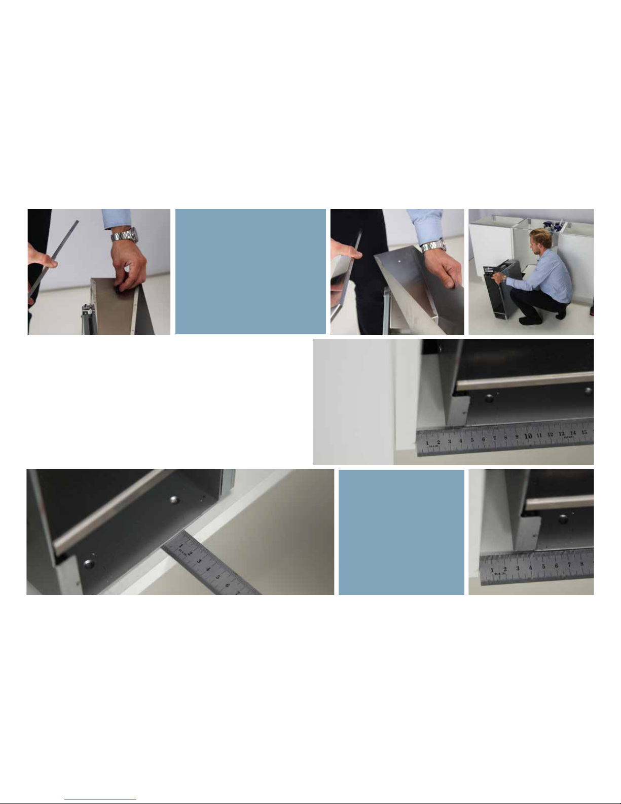
Allow for minimum 30 mm of
clearance on the left side of
the machine and 10 mm on
the front
Page 38
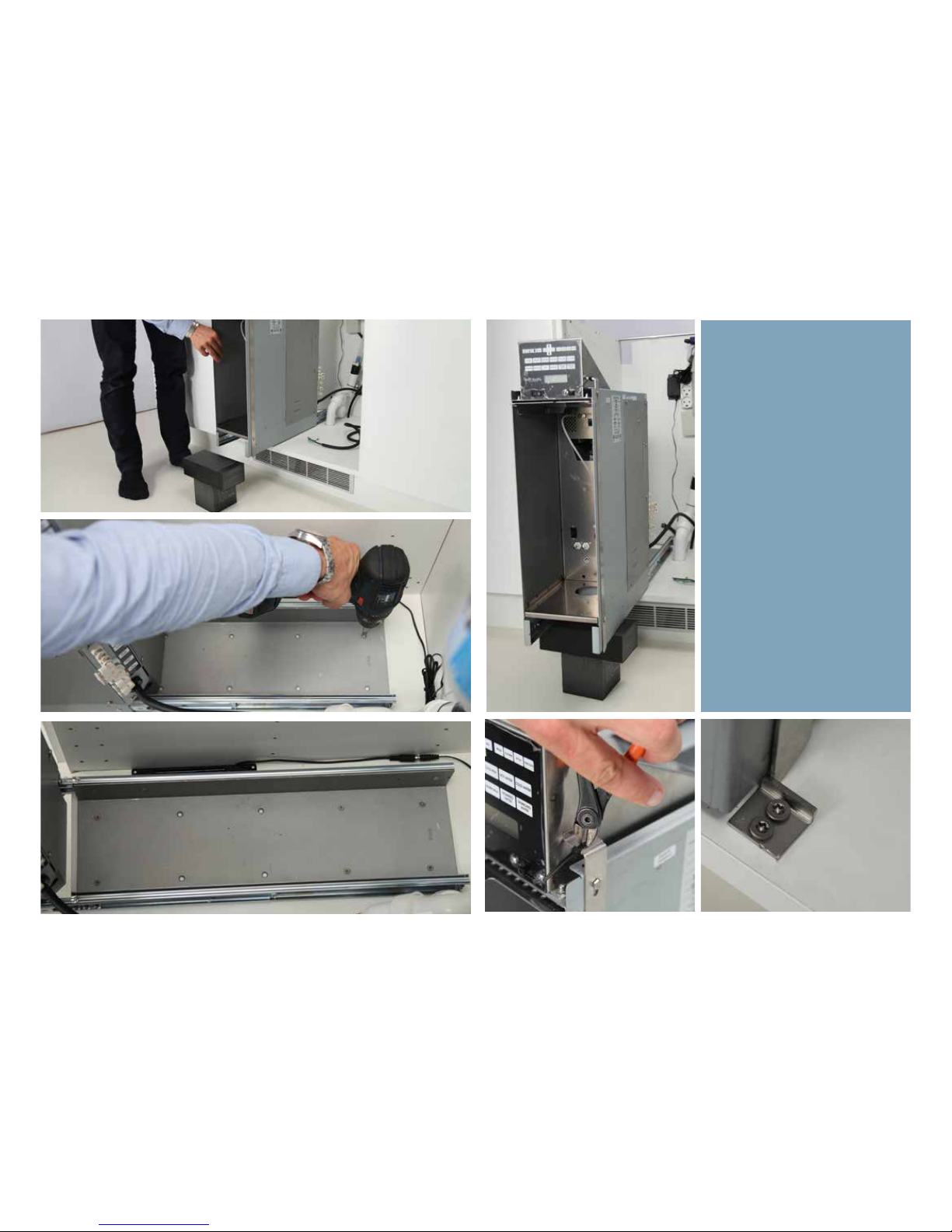
To ease installation, use a support while securing the machine
to the cabinet foor as shown.
Secure the machine with minimum 6 countersunk screws as
shown.
Mount the lock-hinge, preventing the machine from sliding out,
in the bottom of the cabinet.
Page 39
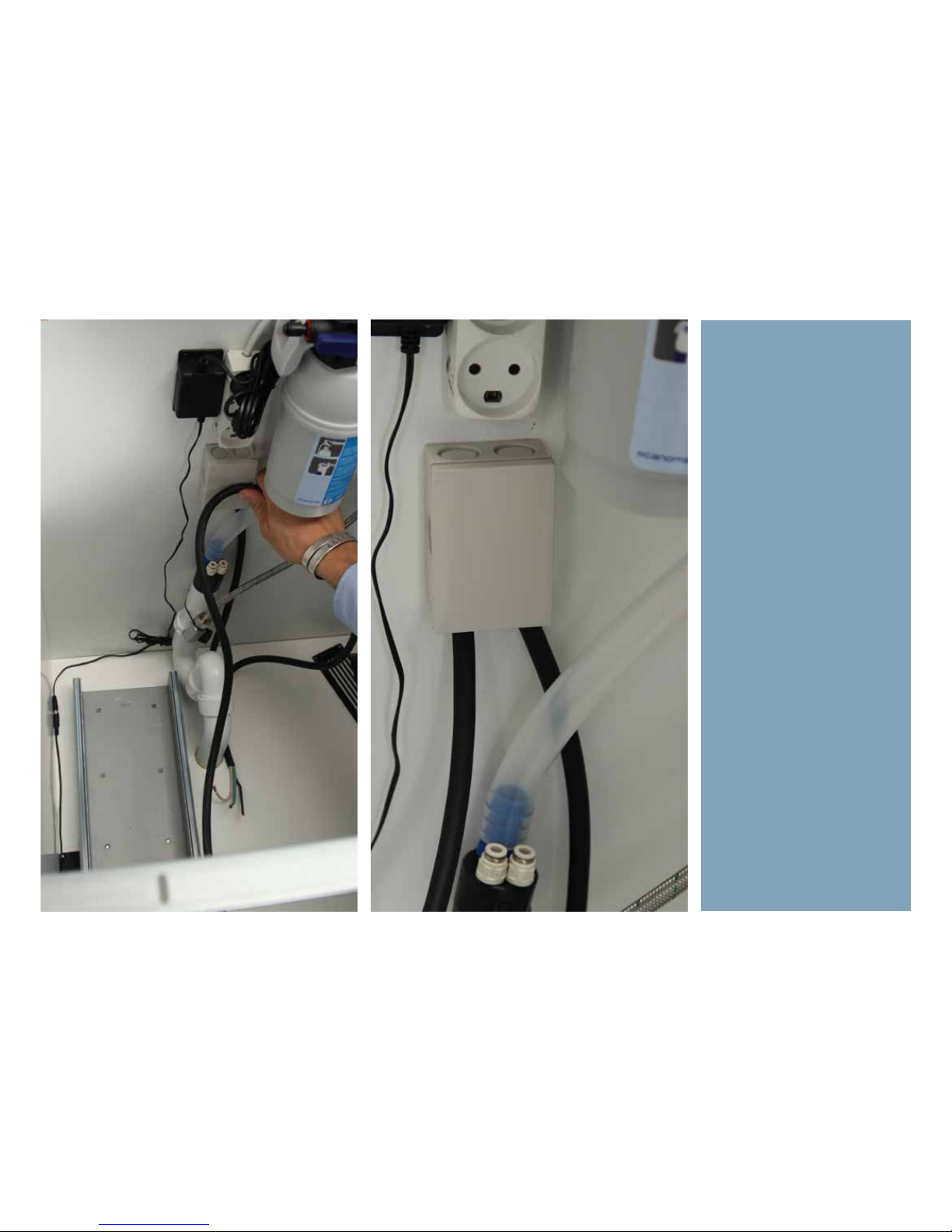
Connect electricity to the main.
Ensure enough lenght, and use
the machine at full extension to
measure the correct distance.
Page 40
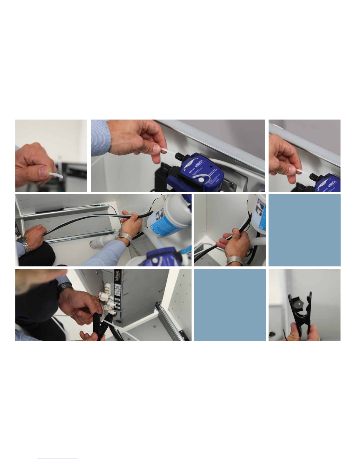
Connect the “From Filter” and
“To Filter” 4mm lines to the
filter we’ve prepared with 0%
bypass, to the female connecters. Ensure once again
the machine can be puled out
and cable-tie alongisde the
power line.
You will need:
A tube-cutter
Cable ties
Page 41
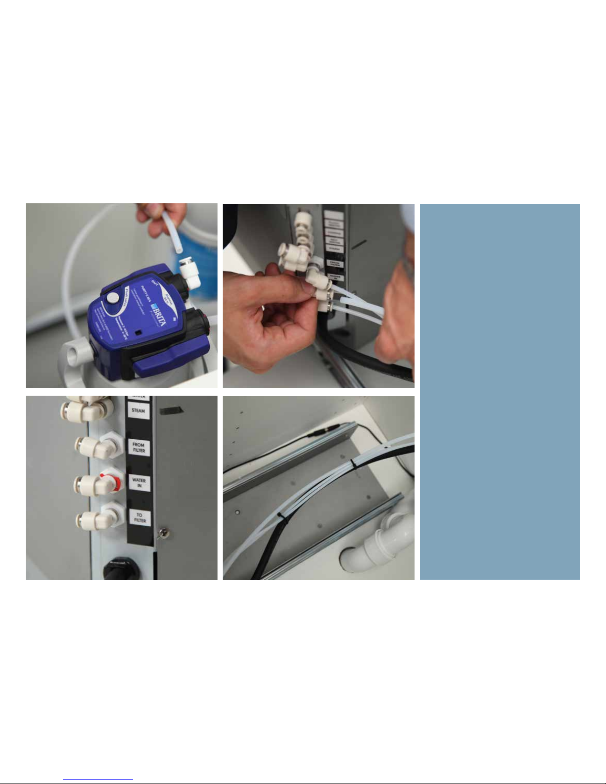
Connect next the main water inlet
to the 30% bypass filter on the “out”
side, using the 6mm line provided
and shorten accordingly. Cabletie
alongside the hoses as well.
Page 42
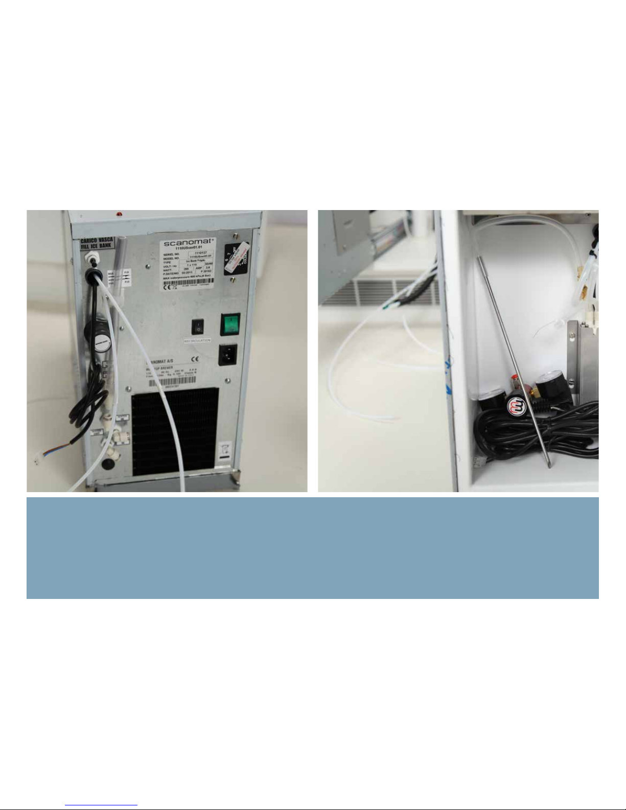
Installing the Fridge
Page 43
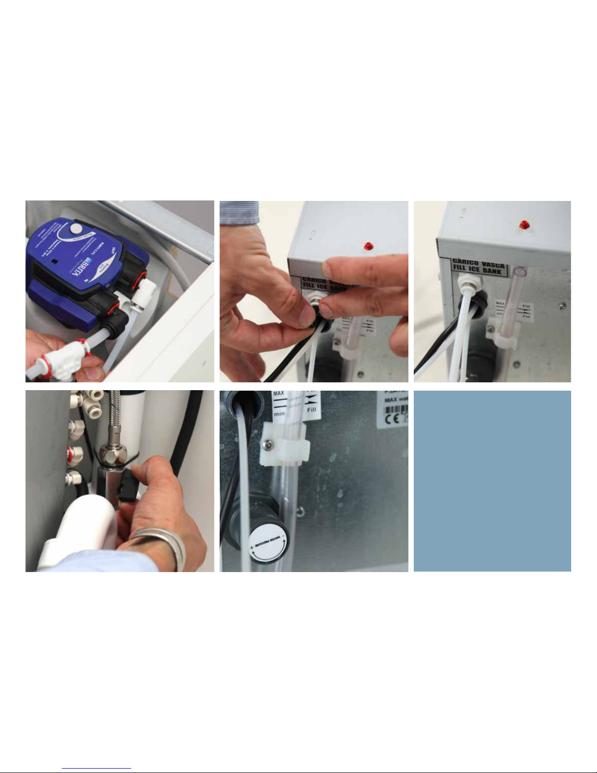
Start by filling the fridge with water,
using the supply line from the ActiveCoal 10.000 filter. Using the shut-o
valve, we can now fill the ICE-bank to
the fill level illustrated on the back of
the machine.
Once finished, ensure to refit the
plug.
Page 44
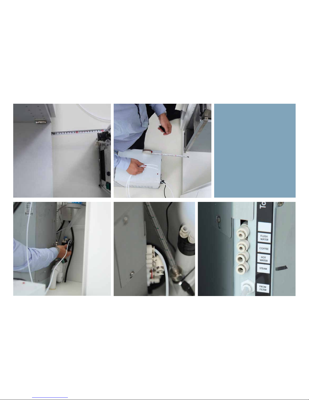
During the installation process, place
the fridge 20 cm from the front of the
cabinet. We’re going to use this distance as our guide in making hoses
and connections the right length.
Connect first the drain line (marked
D) to the drain. This is for the flush
water exiting the fridge. Next, connect the flush water hose, also coming out the back of the fridge, to the
“Flush Water” outlet on the back of
the machine as shown. You can use
an angle if this eases install.
Page 45
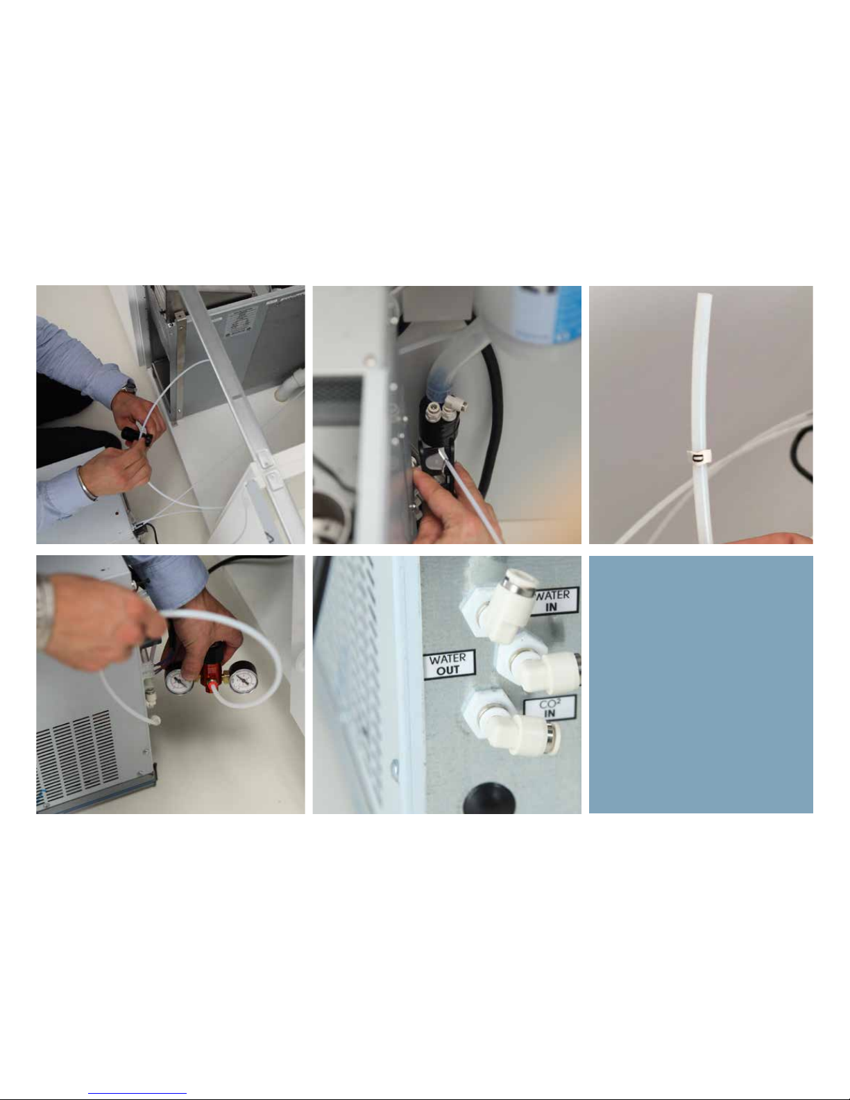
Odip eum am veriusc ipisci tat lut do
voloreratem zzriustrud et nonsequat,
veriusto odolorerit dolum alit vol
borem quat wissi. Ex ent ea faci ercipit
iriure.
Page 46

Installing the Fridge
Page 47
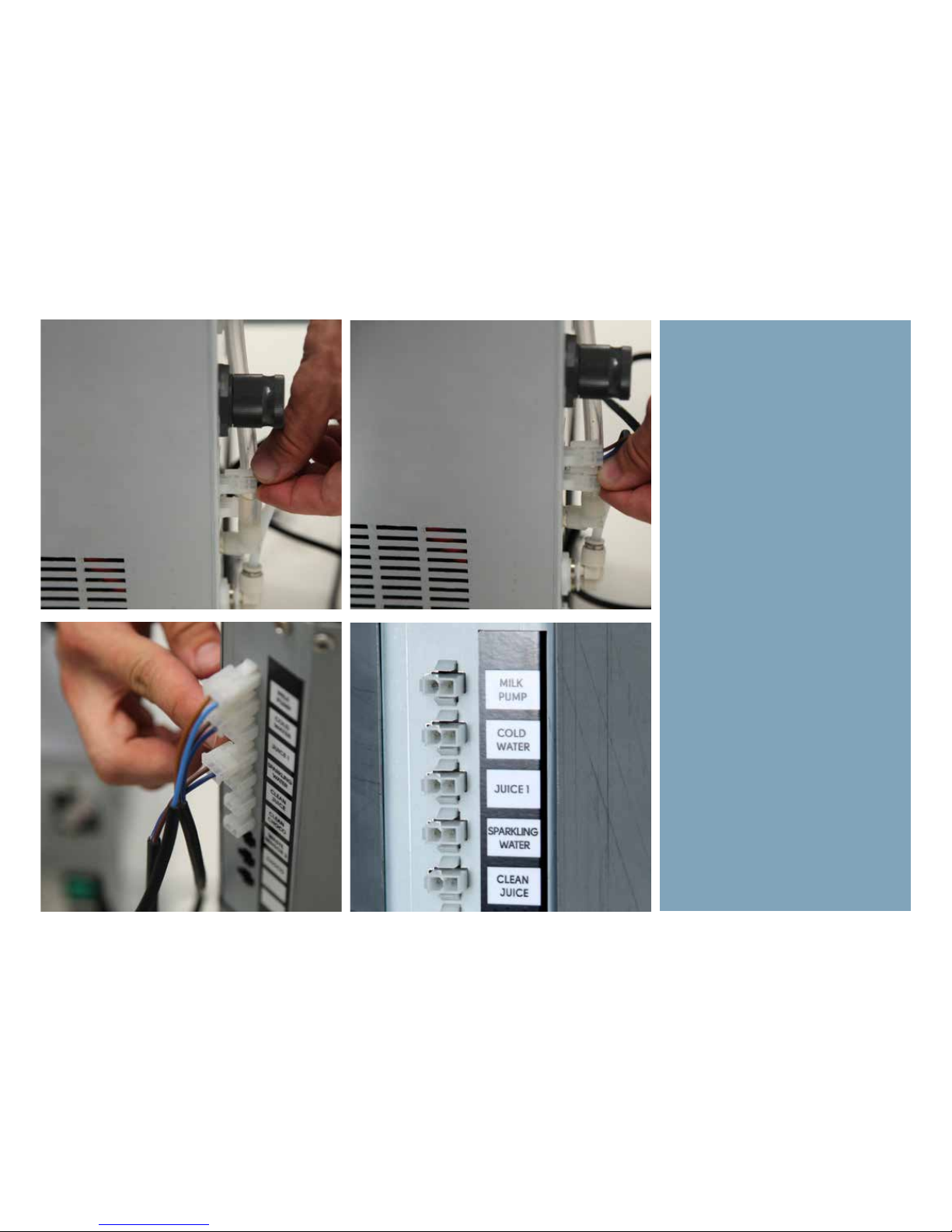
Connect both signal cables. One is
for sparkling water and one is for cold
water. Ensure to match up each end
with the correct plug from the back of
the fridge to the back of the TopBrewer.
Page 48
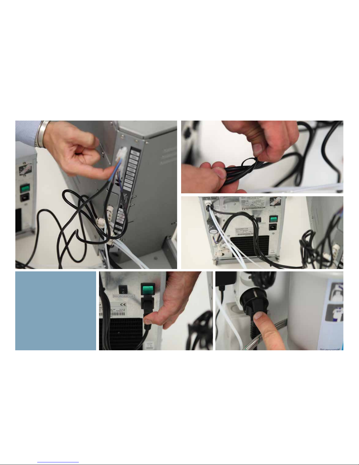
Shorten as much as allowed,
bundle the wires together with a
cable-tie as shown .
Next, fit the electricity cable to
the back of the fridge.
Please turn on the fridge, as it
will take approx 3-4 hours for
it to form ice and subsequently
start cooling. Engage recirculation switch.
Page 49
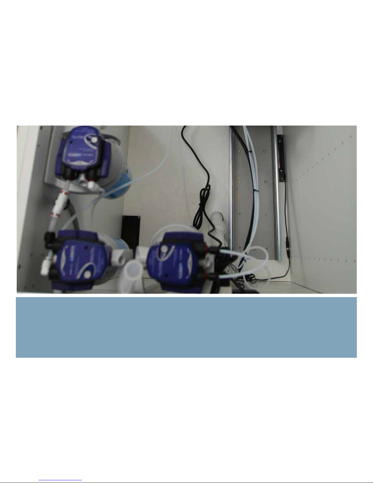
When correctly installed, here shown from the top, fitlers are placed neatly inside the cabint and all hoses and cables are neatly tied
together, creating a well arranged installation area.
Page 50
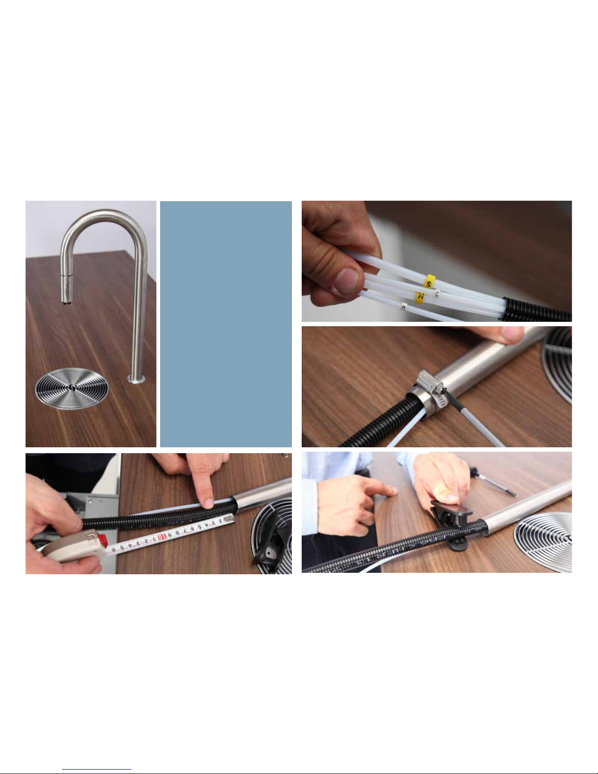
Installing the faucet requires
som preperation steps.
1. Remove the labels, noting with
a marker where they fit
2. Remove the clamp
3. 30 mm from the base, cut o
the insulating hose and save for
later
1
2
3
Page 51
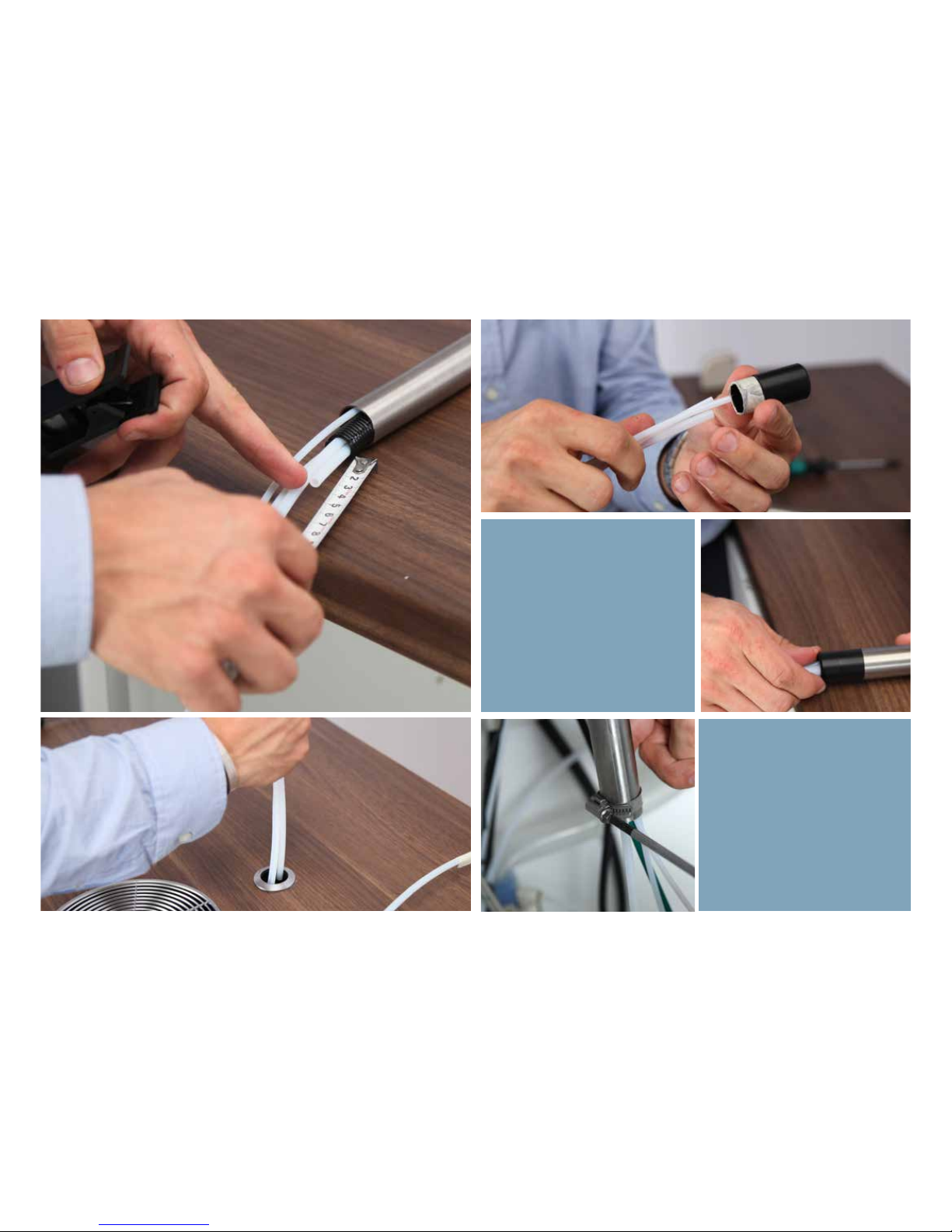
1: Shorten the “hot water” or “W”
hose to 40mm in length.
2. Insert the sleeve that helps the
faucet glide easier through like
shown
3. insert the faucet and secure
the clamp back in place, acting
as a stop.
3
1 2
Page 52
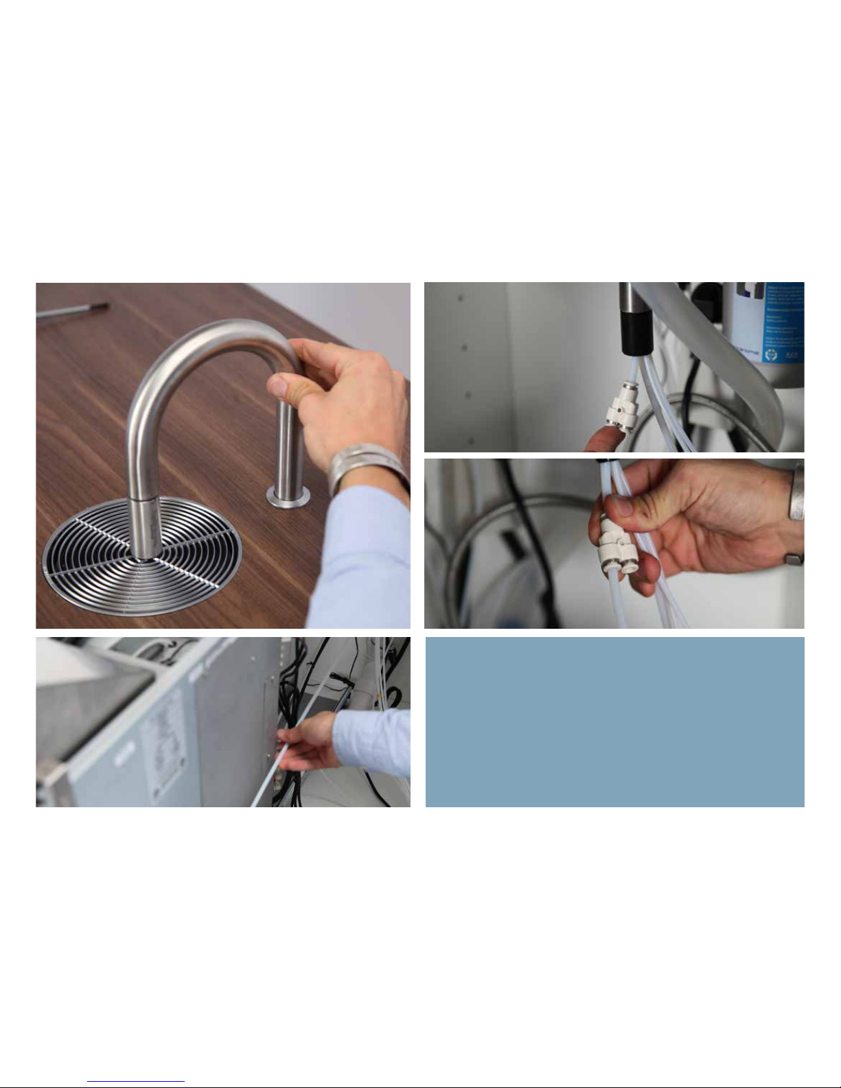
Lower the faucet down to it’s bottom position
Fit the Y-piece onto the “Water” or “W” line that we shortened earlier.
Fit a 6mm hose to one of the inlet of the Y-piece and use the machine, that is stilled pulled out fully, as a guide to making it the right
length.
Page 53
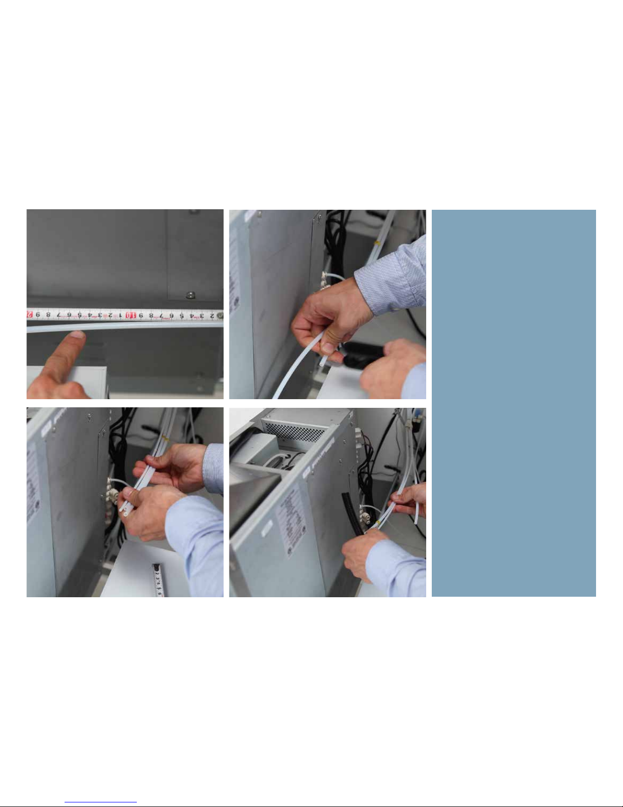
Measure from the back edge of the
machine and 15cm and use this as
your guide to cut the hose.
Use the Water line, that we just cut,
as a guide to shorten the remaining
lines coming out of the faucet.
IMPORTANT!: Do not cut the 4mm
hose, labeled with a “M” for milk.
Leave this aside for now!
Page 54
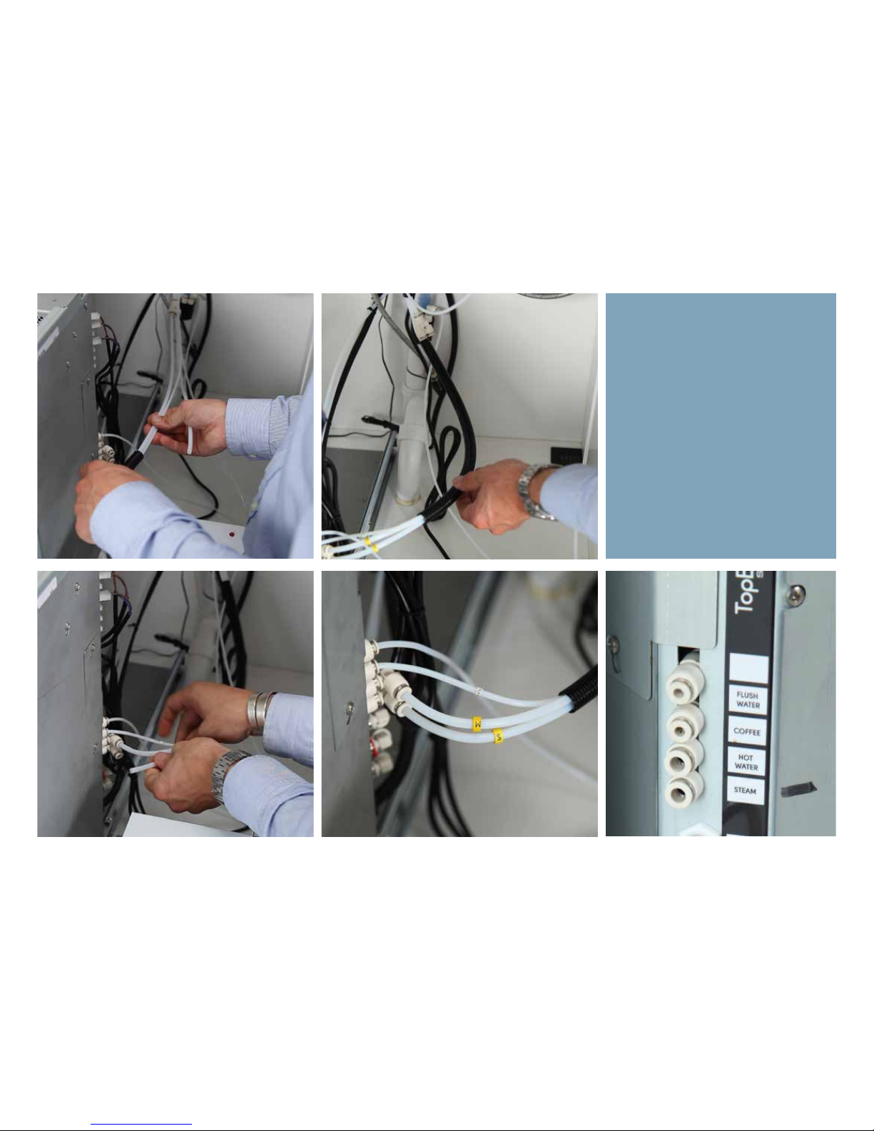
1. Mount the isolation hose. (exlcuding milk line)
2. Fit back labels to their original
place.
3. Connect the lines to the right outlets on the back of the machine.
(see diagram as well)
Use angles to ease the tension on the
lines.vvv
1
2
3
Page 55
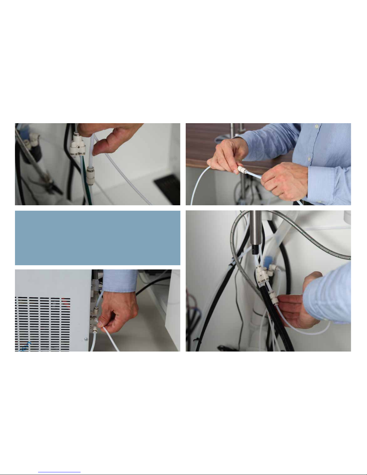
The other leg on the Y-piece is connected to the cold-water
outlet on the fridge. Cut a small length of 6mm hose and fit to a
double-female connector as shown.
Using the 4mm line, which is exactly 1 meter long, connect the
hose to the double-female connector on one end, and the fridge
water-out on the other end as shown
Page 56
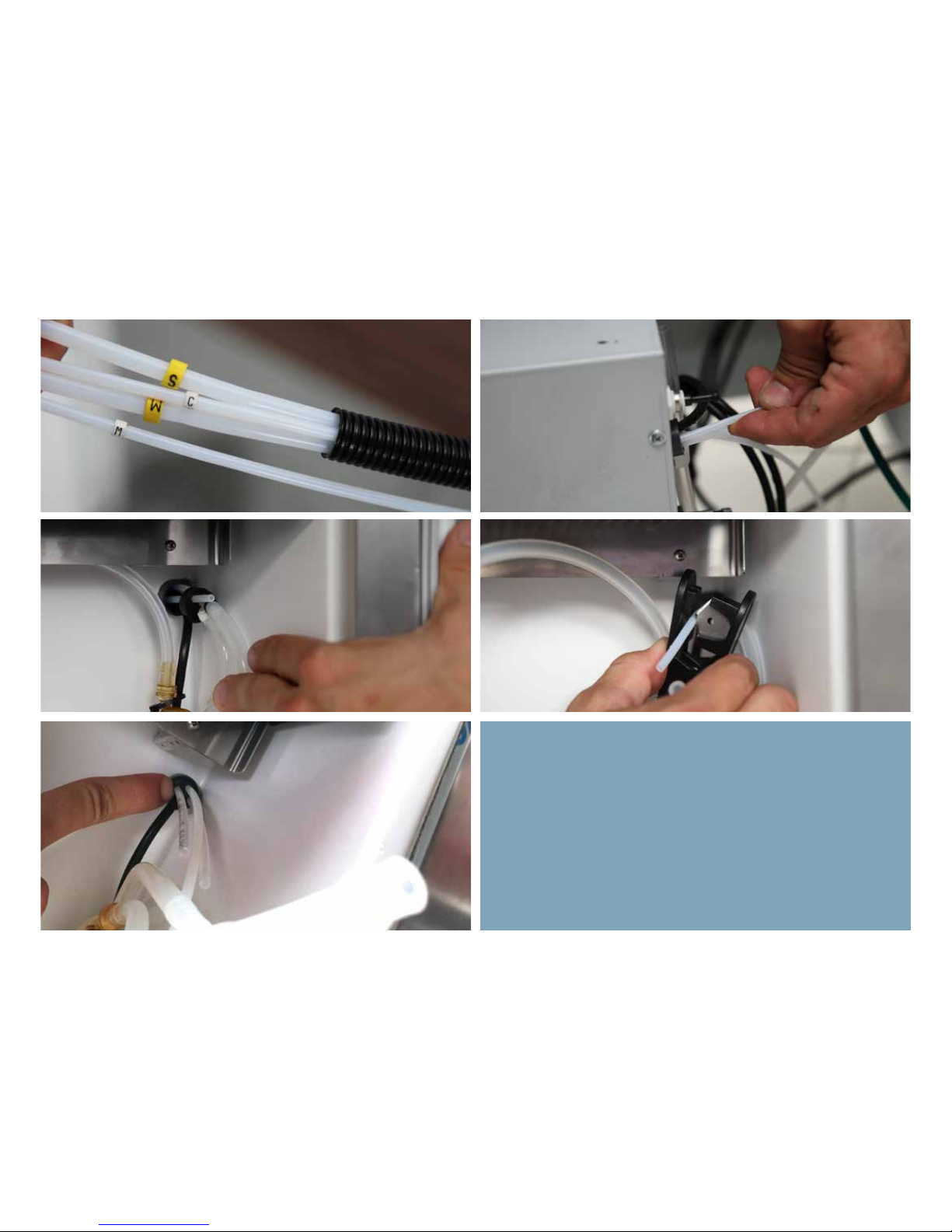
1. Next, locate the milk line that we put aside before.
2. Pertrude the milk line, coming frm the faucet, and into the back
of the fridge as shown above.
3. Poke the line through the rubber seal and pull through as far as it
extends
4. Cut of at an index fingers length.
5. Ensure a proper fit with the rubber seal as show, pushing into the
cylinder
1 2
3 4
5
Page 57
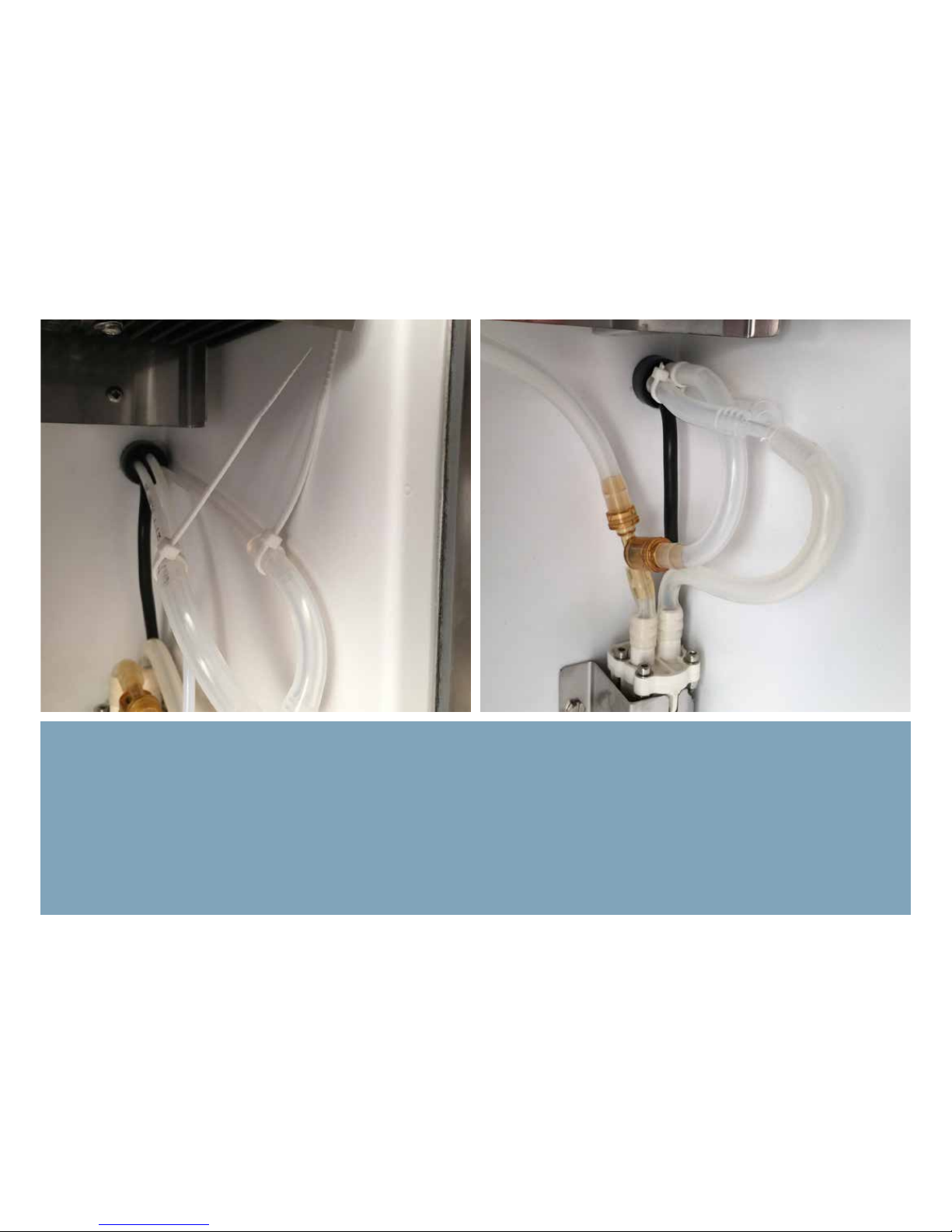
6. Connect the Y-piece, already prepared inside the fridge, to the Milk Line and the Flush Water line and secure with cable-ties as shown.
7. Connect the drain out on the yellow double-valve to the drain line as shown. A fnished installtion sits neatly onto the rubber seal, with
the seal pushed all the way flush with the cylinder to allow no air to pass.
Note: Along the process, ensure to fit labels back to the lines accordingly.
76
Page 58
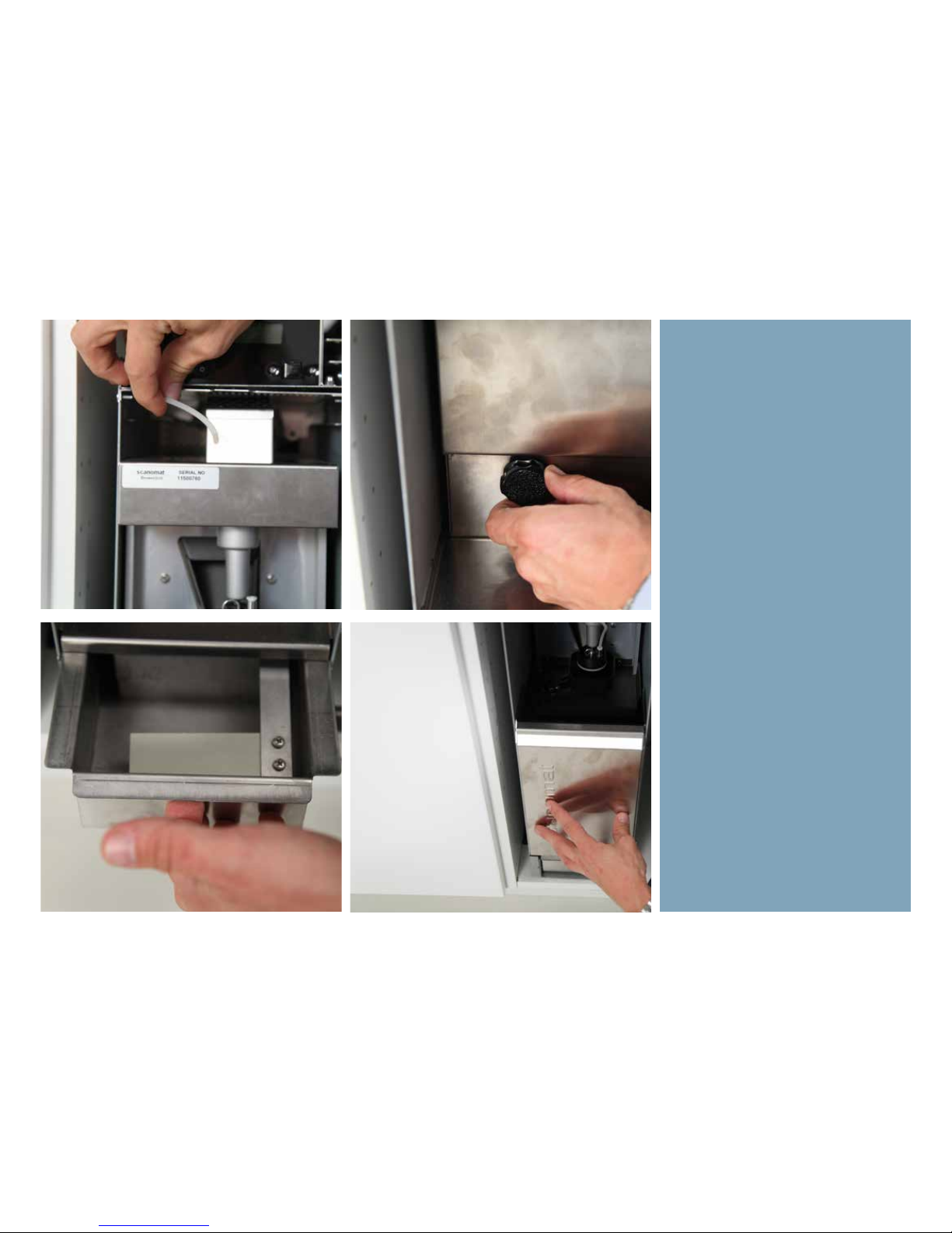
Next, fit back the brewer. Remember
to connect the coee-hose to the top
piston.
Tighten the finger screw, but omit
using tools.
Replace both dreg and wate bin as
shown.
Page 59
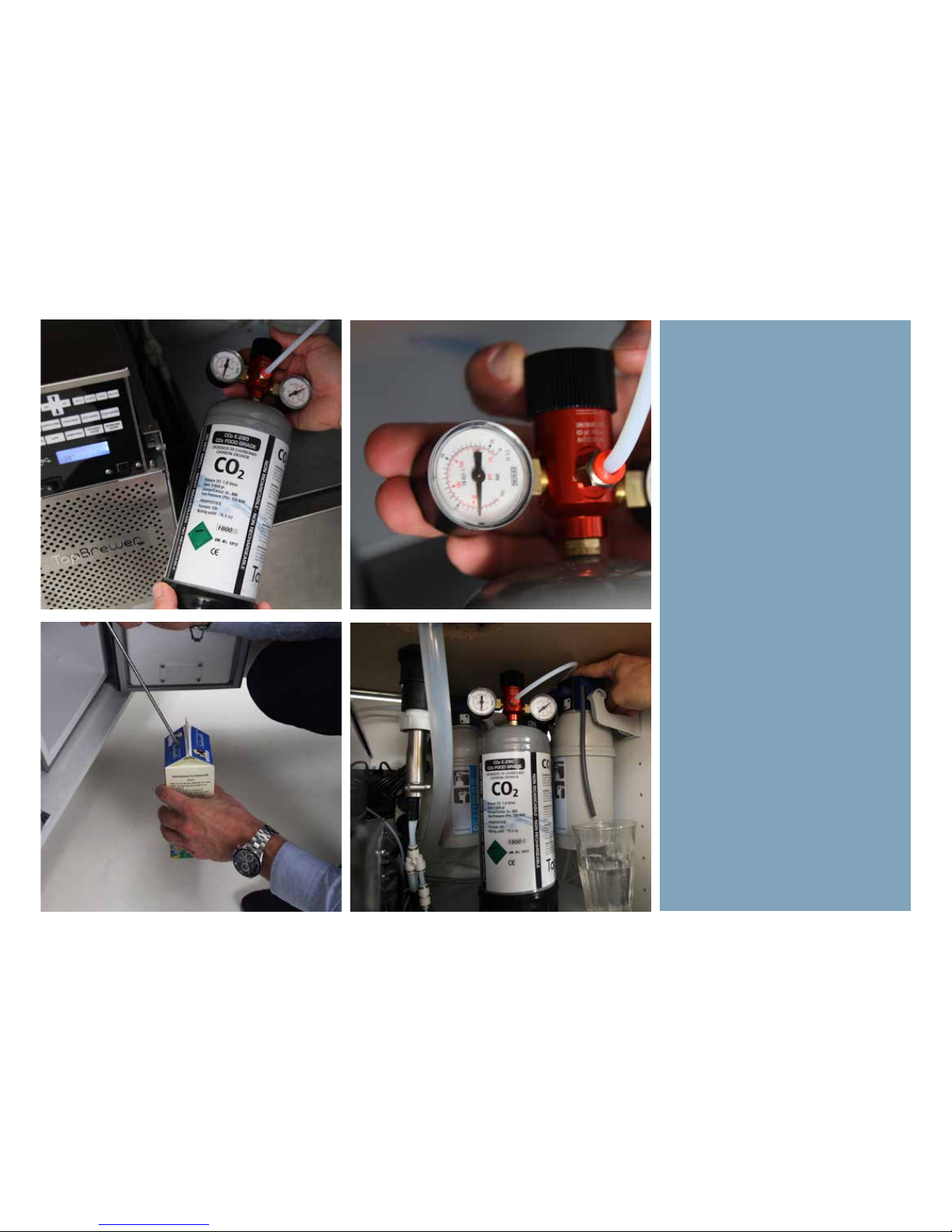
Fit the Co2 bottle (if applicable), using
a 6mm hose going from the back of
the fridge and to the manometer.
Fit the manometer and secure to the
bottle. Do not overtigthen.
Slowly, engage the pressure by rotating the top bevel clockwise.
Pressure setting: 3 bar
The Co2 bottle can by all means, be
placed in an adjacent cabinet.
Use the milk sphere to poke through
a milk carton like shown, once the
milk fridge is producing cooling.
Page 60
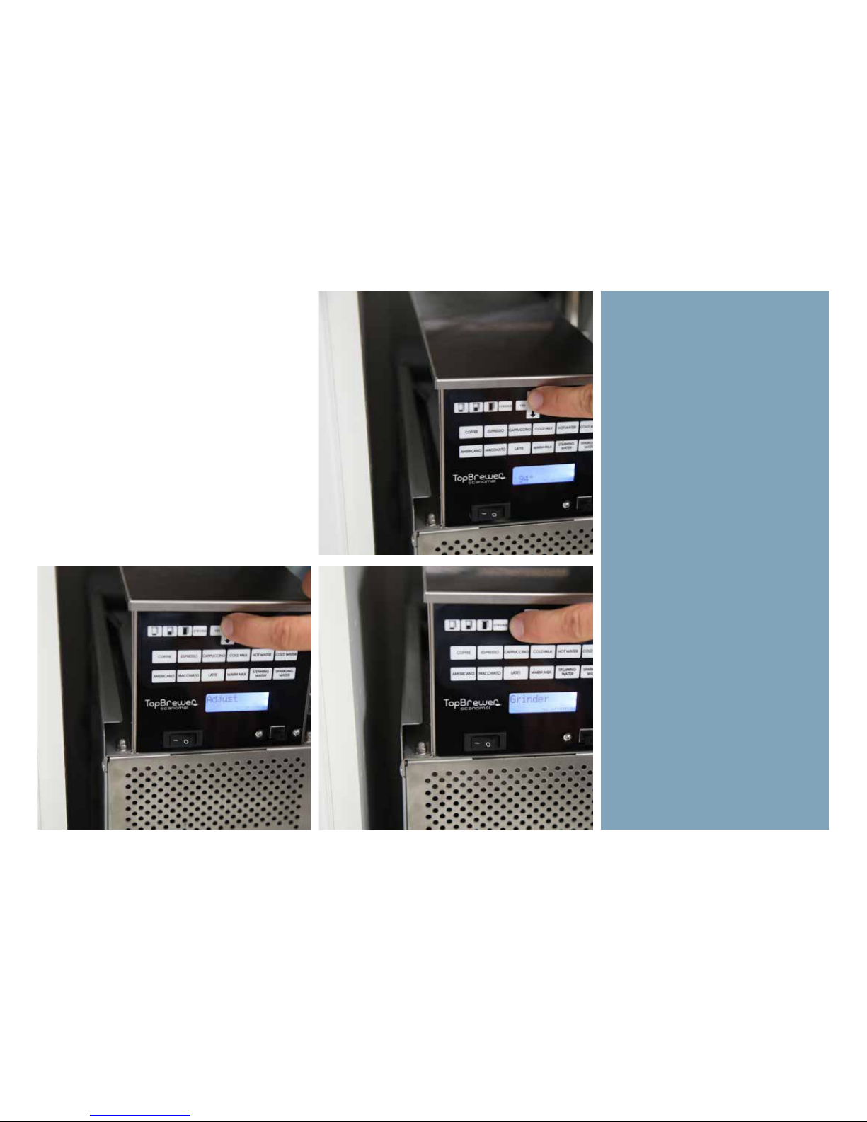
The grinder is delivered at a factory
preset setting and can be adjusted for
optimum extraction.
We recommend doing this when the
machine is getting installed, using
TopBrewer Coee.
1. Pull 1 or 2 espresso shots, standard
of the menu. Measure the time of
the extraction, from the second you
push the button to the second it stops
pouring coee. This time should be
around 30 seconds.
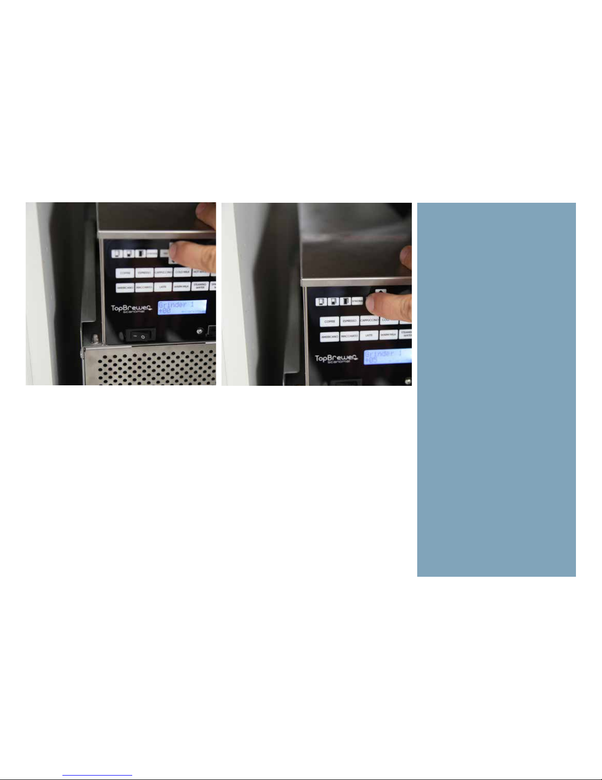
2. To adjust the pour, go to the menu
(arrow up) and located Adjust >
Grinder. Select “Grinder 1”. A greater
number here is finer = longer extraction. A lesser number is coarser =
shorter extraction.
3. Make an adjustment and hit “Yes”
so save. Exit the menu by hitting “No”
or wait a few seconds and the machine will time out.
4. Pull 2 espressos and measure the
second.
5. Repeat accordingly until you get
the result you are looking for.
Adjusting the Grinder
Page 61
Page 62

Page 63
Faucets
Page 64
 Loading...