

Topaz F-FL/70/50K/KN/BZ-67, F-FL/70/50K/SF/BZ-67, F-FL/90/50K/KN/BZ-67, F-FL/70/50K/TR/BZ-67, F-FL/90/50K/SF/BZ-67 Installation Instructions Manual
...
INSTALLATION INSTRUCTIONS FOR LED MEDIUM FLOOD LIGHTS
Items:
F-FL/70/50K/KN/BZ-67
F-FL/70/50K/SF/BZ-67
F-FL/70/50K/TR/BZ-67
F-FL/90/50K/KN/BZ-67
F-FL/90/50K/SF/BZ-67
F-FL/90/50K/TR/BZ-67
Read and follow all safety instructions before beginning installation
Tools Required:
C
rescent Wrench, Wire Strippers, Wire Cutters
WARNING
RISK OF FIRE OR ELECTRIC SHOCK
This product should be installed, inspected, and maintained by a qualified electrician only, in
accordance with the NEC (National Electric Code) and all local codes.
Turn off electrical power before inspection, installation or removal.
Use only UL (or other NTRL) approved wire for input/output connections.
Minimum size 18 AWG or 14 AWG for continuous runs.
Make sure LEDs and drivers are cool to touch when performing maintenance.
Ensure supply voltage is equal to the rated voltage of the luminaire.
Do not install in a hazardous atmosphere, only where the ambient temperature does not exceed the
rated operating temperature of the fixture.
Prepare Electrical Wiring
Electrical Requirements
The LED driver must be supplied with 120V or 277V, 50/60 Hz
and connected to an individual, properly grounded branch circuit
protected by a 20 ampere circuit breaker. Use min. 75°C supply.
Grounding Instructions
The grounding and bonding of the overall system shall be
done in accordance with NEC Article 600 and local codes
925 Waverly Ave • Holtsville, NY 11742 • 800-666-2852 • Fax: 631-758-8026
www.topaz-usa.com
INSTALLATION INSTRUCTIONS FOR LED MEDIUM FLOOD LIGHTS
Items:
F-FL/70/50K/KN/BZ-67
F-FL/70/50K/SF/BZ-67
F-FL/70/50K/TR/BZ-67
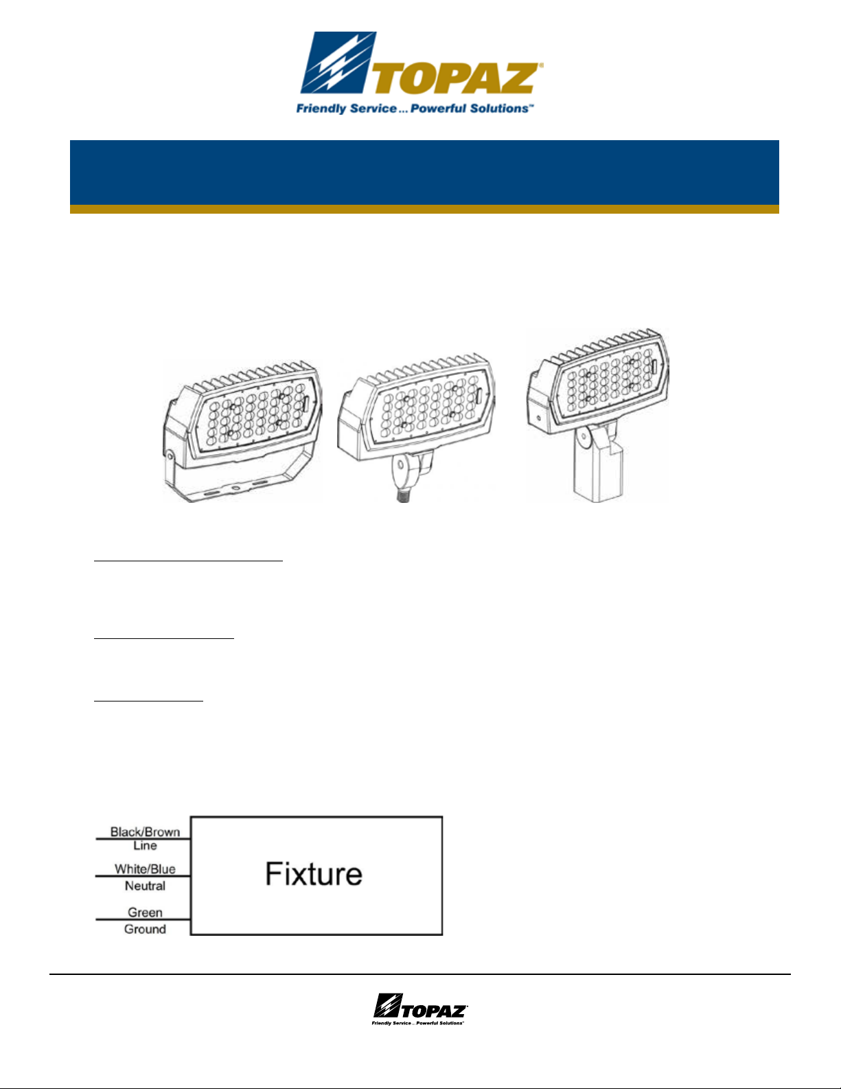
• Before starting make sure that the power is disconnected.
• Unpack fixture and ensure that there are no damaged parts.
• If using Yoke / Trunnion Mount:
• Secure fixture to flat mounting surface using 2 bolts.
• Aim fixture by loosening the 2 bolts on the U-Bracket to the desired angle. Tighten down both bolts.
• Insert power cord into junction box. Ensure there is a water tight seal going into the junction box.
• Wire end of cord to power supply as seen below.
• If using Knuckle Mount:
• Attach fixture to outdoor box cover, routing the fixture wires into the junction box. Connect fixture cables as seen below.
Black to Black, White to White, Green to Green.
• Aim fixture by loosening the bolt on the arm, and reposition to the desired angle. Tighten the bolt.
• If using Slip Fitter:
• For slip fitter installation pass the wires from the slip fitter into the tenon post top.
• Make connections as seen below. Black to Black, White to White, and Green to Green.
• The fixture can be aimed using the tilting motion of the slip fitter and the rotating motion of the slip fitter on the tenon.
• The slip fitter can be tilted by loosening the securing screw and tilting the fixture up or down.
• Once the desired angle is achieved tighten back the securing screw.
• The slip fitter is secured to the tenon by tightening the 2 grub screws on the side.
F-FL/90/50K/KN/BZ-67
F-FL/90/50K/SF/BZ-67
F-FL/90/50K/TR/BZ-67
120-277VAC
UNIVERSAL VOLTAGE
www.topaz-usa.com
925 Waverly Ave • Holtsville, NY 11742 • 800-666-2852 • Fax: 631-758-8026
 Loading...