

Page 1
INSTRUCTION MANUAL
Page 2
Page 2
INTRODUCTION
BEFORE YOU START
The Photon is a professional 1/10 scale touring car and should be built
only by persons aged 16 years or older with previous experience building
and operating R/C model cars. This is not a toy and is not intended for
use by beginners or by children without direct supervision of a responsible,
knowledgeable adult. Read the instruction manual carefully before
building.
T.O.P. Racing shall not be liable for any loss, injury or damages, whether
direct, indirect, special, incidental, or consequential, arising from the use,
misuse, or abuse of this product and/or any product or accessory required
to operate this product.
GENERAL PRECAUTIONS
This product is not suitable for children under 16 years of age without the •
direct supervision of a knowledgeable adult.
Assemble this kit only in places away from the reach of small children.•
First-time builders and users should seek advice from people who have •
building experience in order to assemble the model correctly and to allow
the model to reach its performance potential.
Exercise care when using tools and sharp instruments.•
Take care when building, as some parts may have sharp edges.•
Keep small parts out of reach of small children. Children must not be •
allowed to put any parts in their mouth, or pull vinyl bag over their head.
Immediately after using your model, do not touch equipment on the •
model such as the motor and speed controller, because they generate
high temperatures. You may seriously burn yourself by touching them.
Follow the operating instructions for the radio equipment at all times.•
Do not put fi ngers or any objects inside rotating and moving parts, as •
this may cause damage or serious injury as your fi nger, hair , clothes, etc.
may get caught.
Be sure that your operating frequency is clear before turning on or running •
your model, and never share the same frequency with somebody else at
the same time. Ensure that others are aware of the operating frequency
you are using and when you are using it.
Always turn on your transmitter before turning on the receiver in the car. •
Always turn off the receiver before turning off your transmitter.
Keep the wheels of the model off the ground when checking the operation •
of the radio equipment.
Disconnect the battery pack before storing your model.•
To prevent any serious personal injury and/or damage to property, be •
responsible when operating all remote controlled models.
The model car is not intended for use on public places and roads or •
areas where its operation can confl ict with or disrupt pedestrian or
vehicular traffi c.
Do not use your model:•
Near real cars, animals, or people that are unaware that an RC car 1.
is being driven.
In places where children and people gather2.
In limited indoor spaces3.
In wet conditions4.
In the street5.
In areas where loud noises can disturb others such as hospitals and 6.
residential areas
At night or anytime your line of sight to the model may be obstructed 7.
or impaired in any way.
To prevent any serious personal injury and/or damage to property, please
be responsible when operating all remote controlled models.
ELECTRICAL PRECAUTIONS
Insulate any exposed electrical wiring (using heat shrink tubing or •
electrical tape) to prevent dangerous short circuits. Take maximum care
in wiring, connecting and insulating cables. Make sure cables are always
connected securely. Check connectors for if they become loose. And
if so, reconnect them securely. Never use R/C models with damaged
wires. A damaged wire is extremely dangerous, and can cause shortcircuits resulting in fi re.
Low battery power will result in loss of control. Loss of control can •
occur due to a weak battery in either the transmitter or the receiver
Weak running battery may also result in an out of control car if your
car’s receiver power is supplied by the running battery. Stop operation
immediately if the car starts to slow down.
When not using RC model, always disconnect and remove battery.•
Do not disassemble battery or cut battery cables. If the running •
battery short-circuits, approximately 300W of electrical power can be
discharged, leading to fi re or burns. Never disassemble battery or cut
battery cables.
Use a recommended charger for the receiver and transmitter batteries •
and follow the instructions correctly. Over-charging, incorrect charging,
or using inferior chargers can cause the batteries to become dangerously
hot. Recharge battery when necessary. Continual recharging may
damage battery and, in the worst case, could build up heat leading to
fi re. If battery becomes extremely hot during recharging, please ask your
local hobby shop for check and/or repair and/or replacement.
Regularly check the charger for potential hazards such as damage to the •
cable, plug, casing or other defects. Ensure that any damage is rectifi ed
before using the charger again. Modifying the charger may cause shortcircuit or overcharging leading to a serious accident. Therefore do not
modify the charger.
Always unplug charger when recharging is fi nished.•
Do not recharge battery while battery is still warm. After use, battery •
retains heat. Wait until it cools down before charging.
Do not allow any metal part to short circuit the receiver batteries or other •
electrical/electronic device on the model.
Immediately stop running if your RC model gets wet as may cause short •
circuit.
Please dispose of batteries responsibly. Never put batteries into fi re.•
EQUIPMENT RECOMMENDED (NOT INCLUDED)
Radio Transmitter•
Radio receiver•
Batteries for Transmitter•
Electronic Speed Control•
Steering Servo•
540 Type Motor or Brushless Motor System•
Pinion Gear (64 Pitch)•
7.2V, 6 Cell Sub-C Battery Pack or suitable Li-Po Pack•
190mm Body Shell•
Touring Car Wheels, Tires and Inserts•
TOOLS RECOMMENDED (NOT INCLUDED)
1.5mm, 2.0mm, 3.0mm Allen Wrench•
5.0mm, 5.5mm & 7.0mm Hex Socket Wrench•
Modelers Craft Knife•
Small Cross Head Screw Driver•
Turnbuckle Wrench•
Calipers/Ruler•
Camber Gauge•
Battery Strapping Tape•
Instant Glue/Thread Lock•
Shock Oil•
Thrust Grease, Diff. Grease, Joint Grease•
Paint (for Bodyshell)•
NOTE:
The Photon chassis uses the best available components. All replacement •
parts can be purchased from your local hobby or model shop.
There are 2 versions of the Photon - the Rubber Asphalt Pro Edition and •
the Foam Carpet Pro Edition. Ask you local hobby shops for confi rming
which kit you would like to purchase.
This instruction manual contains a blank setup sheet for your own setup •
record.
Enjoy building and driving your Photon!!
Page 3
Page 3
Mold J-03-1
Mold J-01-1
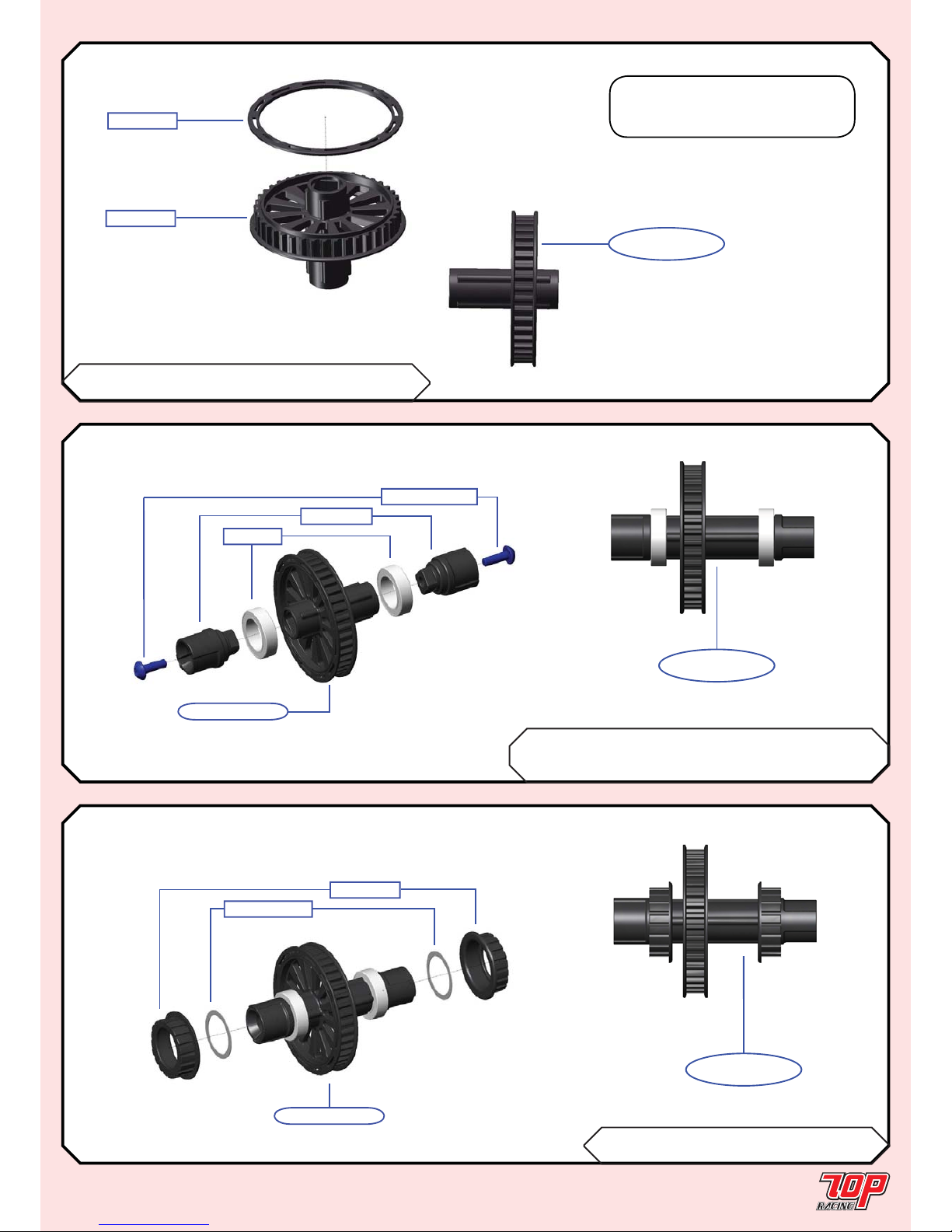
STEP 01
FINISHED
SPOOL (Rubber Asphalt Edition Only)
BAG A Mold J-01-1 Spool x 1
Mold J-03-1 40T Flange - One-way/Spool x 1
Note: Apply small amount of
instant glue in between Mold J-03-1
and Mold J-01-1.
STEP 01
BAG A 6700ZZ-1 10 x15 x 4mm Bearing x 2
PA-BM0314BK-1 M3x14mm Button Head Screw x 2
Mold K-01-1 Spool Outdrive x 2
STEP 02
BAG A PA-101215-C-1 12 x 0.3mm Shim x 2
Mold L-01-1 Bearing Cam x 2
STEP 03
STEP 02
FINISHED
from STEP 01
6700ZZ-1
Mold K-01-1
PA-BM0314BK-1
PA-101215-C-1
Mold L-01-1
from STEP 02
STEP 03
FINISHED
Page 4
Page 4
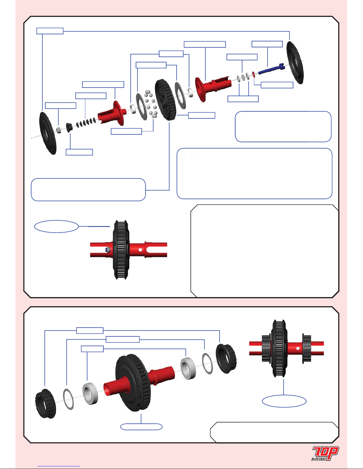
DIFFERENTIAL (Rubber Asphalt Edition - Make 1; Foam Carpet Edition - Make 2)
BAG B Mold L-04-1 40T Diff Pulley x 1
Mold L-05-1 40T Flange/Dust Cover x 2
Mold L-06-1 Differential Nut Retainer x 1
PA-DR0001-1 Diff. Ring x 2
PA-LN0M26-1 M2.6 Locknut x 1
PA-SDB301-1 3mm Diff. Balls x 12
PA-SDB401-1 Thrust Balls x 8
TC-PDT001-1 M2.6 Diff. Screw x 1
TC-PDT002RD-A-1 Alloy Diff. Outdrive - A x 1
TC-PDT002RD-B-1 Alloy Diff. Outdrive - B x 1
TC-PDT003-1 2.6mm Thrust Washer x 2
TC-PDT004-1 Diff. Cone Washers x 6
AW-S050RD-1 3 x 5.5 x 0.5mm Collar x 1
MR85ZZ-1 5 x 8 x 2.5mm Bearing x 2
STEP 04
STEP 05
BAG B PA-101215-C-1 12 x 0.3mm Shim x 2
Mold L-01-1 Bearing Cam x 2
6700ZZ-1 10 x 15 x 4mm Bearing x 2
Note: Apply small amount of black
grease (not included) in between the
2.6mm thrust washers and at the
thrust balls.
Note: The tightness of the diff. is controlled by the diff.
screw. It should be adjusted according to driving style and
track condition. To avoid the end of the diff. screw from
touching the dog bone C drive in STEP 15 when using smaller
rear toe-in or larger camber angles, reduce the number of diff.
cone washers to 4 pcs or use our optional 44.5mm universal
bone (SOLD SEPARATELY).
STEP 04
FINISHED
PA-101215-C-1
6700ZZ-1
from STEP 04
Mold L-01-1
STEP 05
FINISHED
Note: Apply small amount o
f
g
rease (not included) in bet
w
2.6
mm thrust washers an
d
thrust ball
s.
te
The tightness of the diff. is controlled by t
h
Mold L-05-1
PA-DR0001-1
Note: Apply small amount of diff. grease
(not included) in between the diff. rings and
at diff. balls.
MR85ZZ-1
TC-PDT003-1
TC-PDT001-1
PA-SDB401-1
TC-PDT004-1
Mold L-06-1
PA-LN0M26-1
TC-PDT002RD-A-1
TC-PDT002RD-B-1
PA-SDB301-1
Mold L-04-1
AW-S050RD-1
Page 5
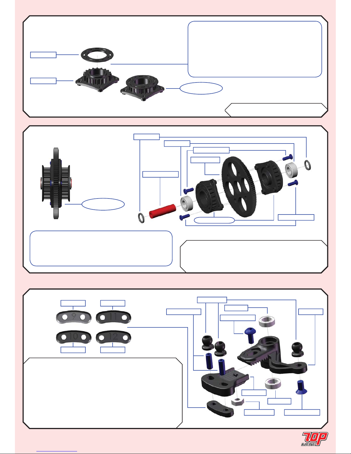
Page 5
CENTER DRIVE
STEP 06
STEP 08
Rubber Foam
BAG C Mold I-01-1 Bell Crank x 1 x 1
Mold I-02-1 Bell Crank Extension x 1 x 1
Mold I-04-1 BCE Insert #10 x 1
Mold I-05-1 BCE Insert #11 x 1
MR85ZZ-1 5 x 8 x 2.5mm Bearing x 2 x 2
PA-BM0306BK-1 M3x6mm Button Head Screw x 1 x 1
PA-FN00M3-1 M3 Nut x 1 x 1
PA-HBS003-1 5.3mm Ball (Steel) x 3 x 3
PA-SS0308BK-1 M3x8mm Set Screw x 2 x 2
PA-CM0306BK-1 M3x6mm Countersunk Screw x 1 x 1
BAG C Mold L-07-1 Center Shaft Spacer x 2
MR105ZZ-1 5 x 10 x 4mm Bearing x 2
SG-K64100-1 100T 64P Spur Gear x 1
TC-PDT005RD-1 Centre Pulley Shaft x 1
PA-SCM205BK-1 M2x5mm Chess Head Screws x 4
STEP 07
BAG C Mold L-02-1 20T Pulley x 2
Mold L-03-1 20T Flange x 2
STEERING CRANK
STEP 07
FINISHED
Mold L-07-1
MR105ZZ-1
SG-K64100-1
PA-SCM205BK-1
TC-PDT005RD-1
from STEP 06
PA-SCM205BK-1
Mold L-02-1
Mold L-03-1
STEP 06
FINISHED
Note: Apply a small amount of instant glue in
betwwen the 20T pulley and 20T fl ange. Be careful
not to let the glue go onto the teeth of the pulleys.
The fi tting between Mold L-03-1 and Mold L-02-1 are
purposefully designed to have a tight fi tting. Be very
carefull when applying instant glue at the contact edge
AFTER the 2 parts are locked together.
Make a total of 2 sets for this step.
Mold I-03-1
Mold I-06-1
Mold I-04-1
Mold I-05-1
PA-HBS003-1
PA-SS0308BK-1
PA-BM0306BK-1
MR85ZZ-1
MR85ZZ-1
Mold I-02-1
Mold I-01-1
PA-FN00M3-1 PA-CM0306BK-1
Note: Slightly ream out both sides of the four 3mm
holes on the spur gear where the 20T pulleys go into,
because plastic burr may exist at these locations. Use
ONLY T.O.P. and Xenon spur gears. These are the ones
that fi t best with our 20T pulleys.
Page 6
Page 6
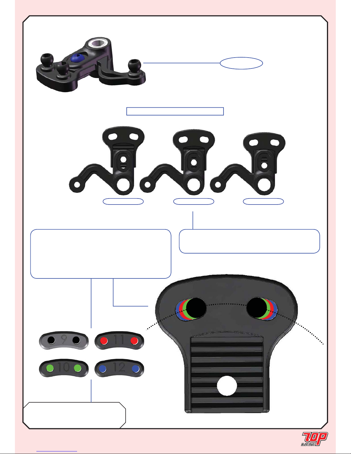
STEERING CRANK (cont’d)
STEP 08 cont’d
BAG C Mold I-03-1 BCE Insert #9 x 1
Mold I-04-1 BCE Insert #10 x 1
Mold I-05-1 BCE Insert #11 x 1
Mold I-06-1 BCE Insert #12 x 1
STEERING GEOMETRIES
Position A Position CPosition B
Note: Length Adjustments
There are a total of 3 steering lenght positions as shown
above. Use Position C as the initial setup.
Note: Radial Adjustments
This is our latest innovation of steering geometry
adjustment. By using the following inserts, the steering
width could be adjusted radially with minimal change in
radial steering length. This would isolate the steering
geometry change created by the steering length
adjustment described in the Length Adjustments.
STEP 08
FINISHED
Page 7
Page 7
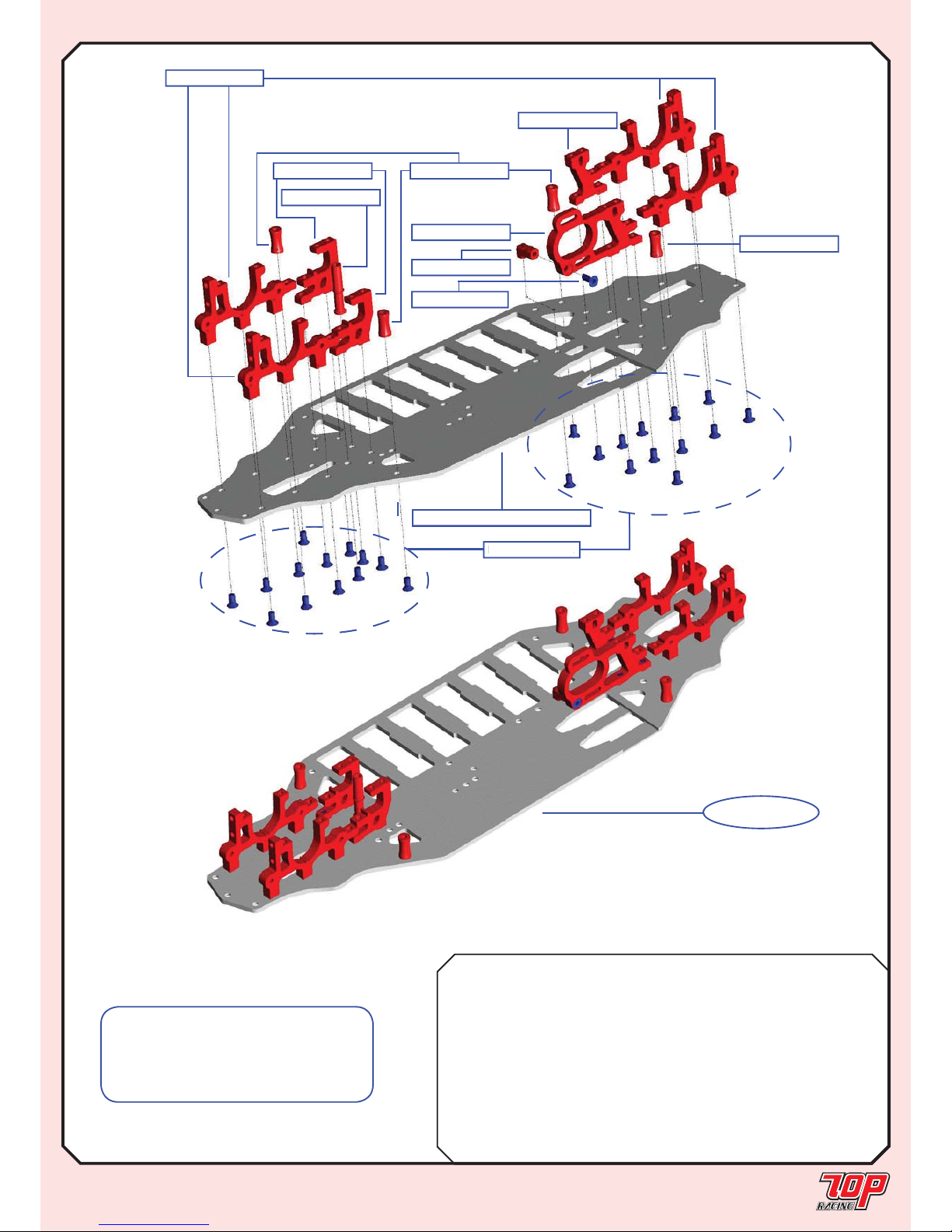
STEP 09
MAIN CHASSIS
Rubber Foam
BAG D TC-PCHC001-1 6-cell Rubber Chassis (2.5mm) x 1
TC-PCHS002-1 6-cell Foam Chassis (3.0mm) x 1
TC-PCH011RD-1 Bulkhead x 4 x 4
TC-PCH012RD-1 Steering Mount Plate x 2 x 2
TC-PCH013RD-1 Motor Plate x 1 x 1
TC-PCH014RD-1 Motor Plate Support x 1 x 1
TC-PCH015RD-1 Mount Plate x 1 x 1
TC-PCH017RD-1 Steering Post x 1 x 1
TC-PCH016RD-1 Standoff Post (12mm) x 4
PA-CM0306BK-1 M3x6mm Countersunk Screw x 22 x 26
PA-CM0308BK-1 M3x8mm Countersunk Screw x 1 x 1
Note: Pay special attention to the
parts table. Not all parts on the list are
needed to complete this step, depending
on whether your kit is rubber asphalt
edition or foam carpet edition!!
TC-PCHC001-1/ TC-PCHS002-1
TC-PCH011RD-1
TC-PCH012RD-1
TC-PCH013RD-1
TC-PCH014RD-1
TC-PCH015RD-1
TC-PCH017RD-1
TC-PCH016RD-1
PA-CM0306BK-1
PA-CM0308BK-1
TC-PCH016RD-1
PA-CM0306BK-
1
STEP 09
FINISHED
Page 8
Page 8
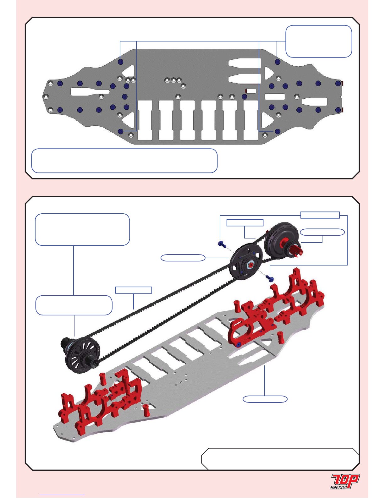
STEP 09 (con’d)
MAIN CHASSIS (con’d)
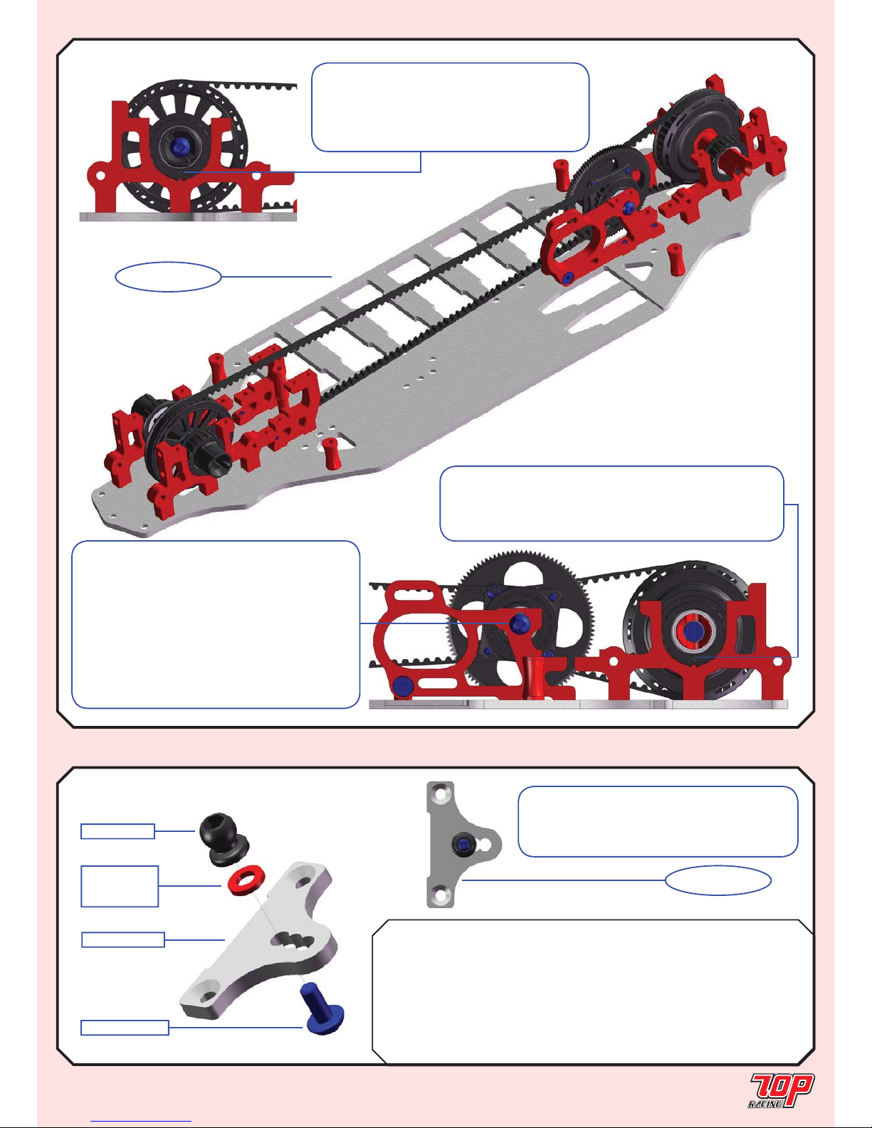
BAG E TC-PDT006M-1 189mm Rear Belt x 1
TC-PDT007M-1 516mm Front Belt x 1
PA-BM0308BK-1 M3x8mm Button Head Screw x 2
Note: To make sure all parts are assembled correctly, the
above fi gure shows how the bottom of the chassis looks like and
where the locations of the occupied screw holes should be.
Note: These screw
holes should only be
occupied by the foam
edition chassis.
STEP 10
TRANSMISSION
TC-PDT006M-1
from STEP 07
TC-PDT007M-1
PA-BM0308BK-1
from STEP 04
Rubber Edition: from STEP 03
Foam Edition: from STEP 04
from STEP 09
Note: The front pulley should
be a spool for the rubber asphalt
edition and a differential for the
foam carpet edition.
Page 9
Page 9
STEP 10
FINISHED
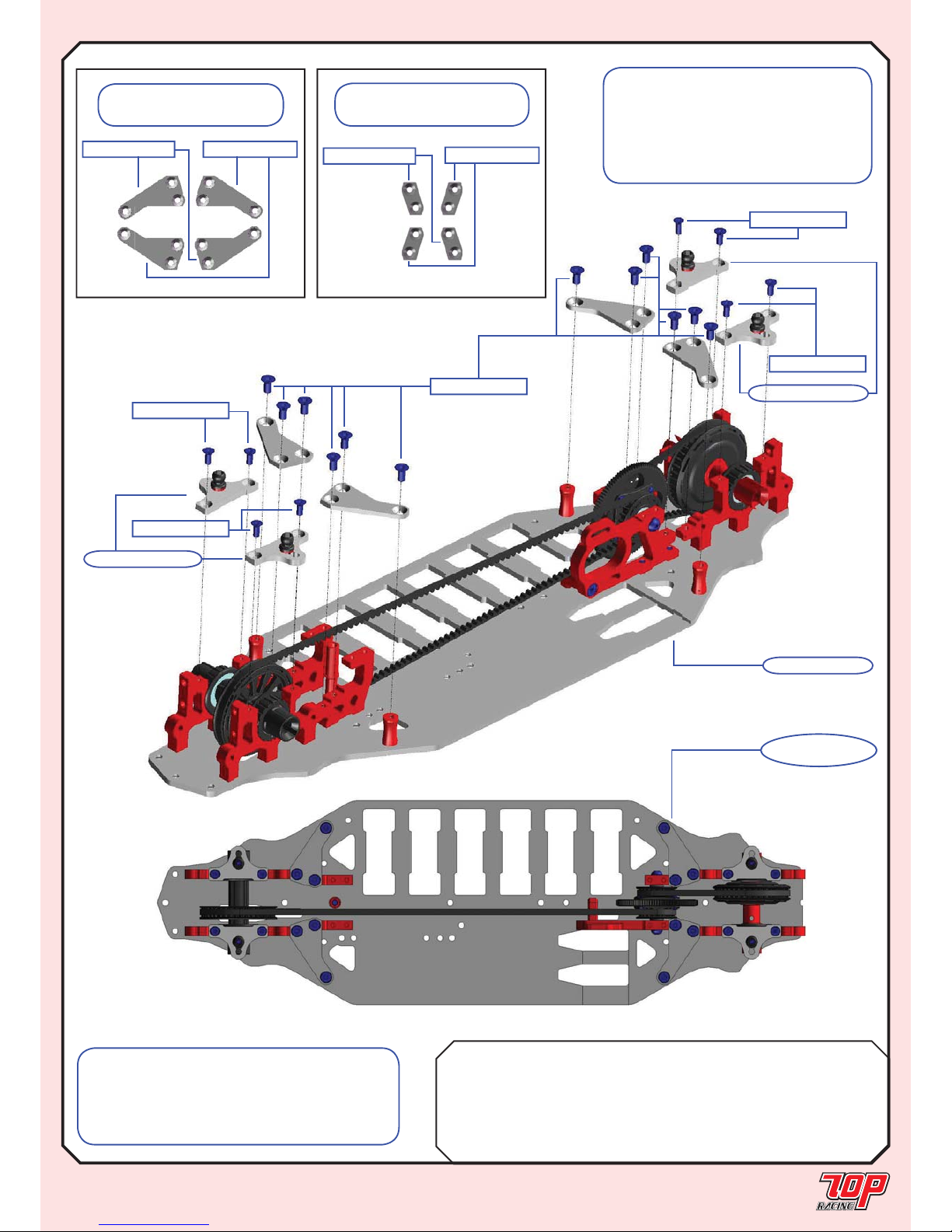
STEP 10 (con’d)
TRANSMISSION (con’d)
Rubber Foam
FRFR
BAG F TC-PCHC008-1 Camber Link Plate (2.5mm) x 2 x 2 x 2 x 2
AW-S250RD-1 3 x 5.5 x 2.5mm Collar x 2
AW-S150RD-1 3 x 5.5 x 1.5mm Collar x 2
AW-S200RD-1 3 x 5.5 x 2.0mm Collar x 2
AW-S200RD-1 3 x 5.5 x 2.0mm Collar x 2
PA-HBS003-1 5.3mm Ball (Steel) x 2 x 2 x 2 x 2
PA-BM0308BK-1 M3x8mm Button Head Screw x 2 x 2 x 2 x 2
Note: Pay attention to the initial orientation
of the bearing cam as shown. Rotate the
cam forward to loosen the front belt and
backward to tighten it. You might have to
loosen it for your fi rst 2 runs with the car.
UPPER CHASSIS
STEP 11 (Make 2 x Front & 2 x Rear)
STEP 11F, R
FINISHED
TC-PCHC008-1
AW-SxxxRD-1
See parts table
for collar size
PA-HBS003-1
PA-BM0308BK-1
Note: Pay attention to the initial position
of the center drive assembly. It is set at its
lowest. The position should be heightened
when using a larger spur gear to avoid touching
the main chassis. If you choose to heighten
the position of the center drive assembly, pay
attention to whether the front drive belt touches
your pinion. If that’s the case, you would have
to use a larger pinion or spur gear, or choose
not to heighten the assembly too much.
Note: Pay attention to the initial orientation of
the bearing cam as shown. Rotate the cam backward to
loosen the rear belt and forward to tighten it. You might
have to loosen it for your fi rst 2 runs with the car.
Note: This is the initial setup for the
camber ball stud position of the rubber asphalt
edition. Refer to the foam standard setup in
Page 30 for the foam carpet edition.
Page 10
Page 10
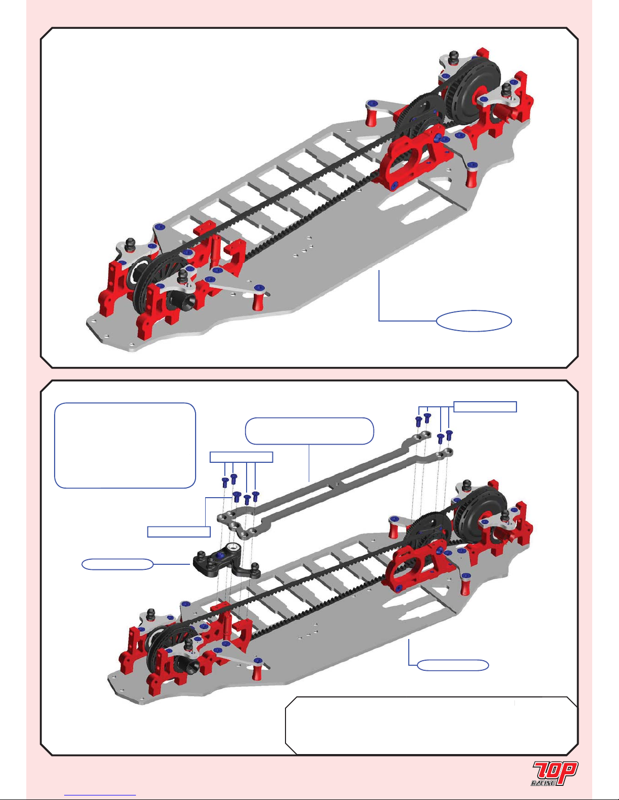
from STEP 11F
from STEP 11R
PA-CM2506BK-1
PA-CM2506BK-1
PA-CM2506BK-1
PA-CM2506BK-1
PA-CM0306BK-1
L
L
R
R
from STEP 10
STEP 12
UPPER CHASSIS (con’d)
Rubber Foam
BAG F TC-PCH009-L-1 Rubber Wing L Soft (2.0mm) x 2
TC-PCH009-R-1 Rubber Wing R Soft (2.0mm) x 2
TC-PCH010-L-1 Foam Wing L Hard(2.0mm) x 2
TC-PCH010-R-1 Foam Wing R Hard (2.0mm) x 2
PA-CM0306BK-1 M3x6mm Countersunk Screw x 8 x 12
PA-CM2506BK-1 M2.5x6mm Countersunk Screw x 8 x 8
Note: Pay special attention to the parts
table. Not all parts on the list are needed to
complete this step, depending on whether your
kit is rubber asphalt edition or foam carpet
edition.
STEP 12
FINISHED
Note: The following fi gure shows
only the foam carpet wing installation.
Follow the orientations shown on
the boxes on your left for the wing
installation for the rubber asphalt and
foam carpet edition, respectively.
LR
R
L
TC-PCH010-L-1 TC-PCH010-R-1
Note: Wings for Foam
Carpet Edition
L
L
R
R
TC-PCH009-L-1
TC-PCH009-R-1
Note: Wings for Rubber
Asphalt Edition
Page 11
Page 11
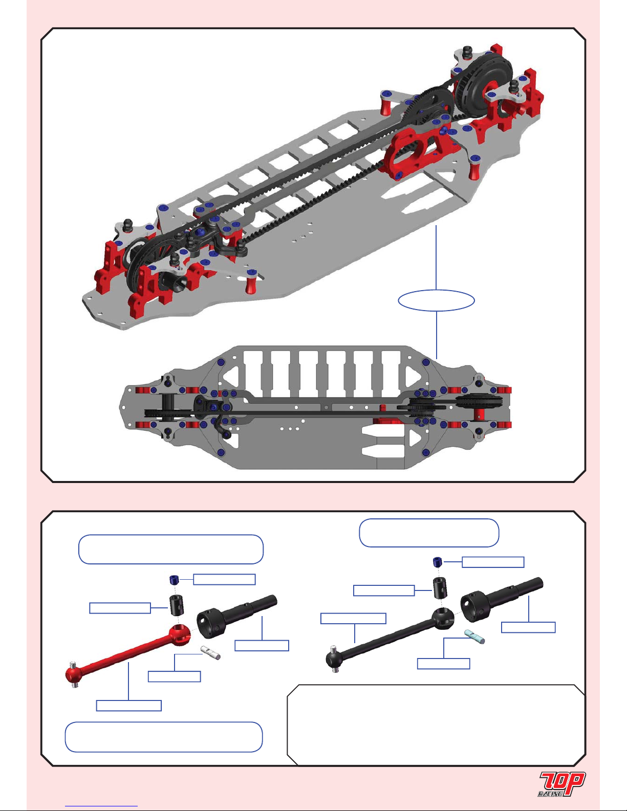
STEP 12 (con’d)
UPPER CHASSIS (con’d)
STEP 12
FINISHED
Rubber Foam
BAG F TC-PCHC004-1 Rubber Top Deck (2.0mm) S x 1
TC-PCHS005-1 Foam Top Deck (2.5mm) H x 1
PA-CM2506BK-1 M2.5x6mm Countersunk Screw x 8 x 8
PA-CM0306BK-1 M3x6mm Countersunk Screw x 1 x 1
STEP 13
Note: Pay special attention
to the parts table. Not all
parts on the list are needed to
complete this step, depending
on whether your kit is rubber
asphalt edition or foam carpet
edition.
ay special attention
rts table. Not all
he list are needed to
this step, depending
er your kit is rubber
ition or foam carpet
from STEP 12
PA-CM0306BK-1
PA-CM2506BK-1
from STEP 08
Rubber Edition: TC-PCHC004-1
Foam Edition: TC-PCHS005-1
PA-CM2506BK-1
Page 12
Rubber Foam
BAG G PO-SDT026RD-1 44.5mm Universal Bone (Alloy) x 2 x 4
PO-SDT009RD-1 46mm Universal Bone (Alloy) x 2
PO-SDT018-1 Universal Axle x 4 x 4
PO-SDT011-A-1 Universal Insert x 4 x 4
PO-DT0011-1 2 x 10mm Universal Pin x 4 x 4
PA-SS0303BK-1 M3x3mm Set Screw x 4 x 4
Page 12
STEP 13 (con’d)
UPPER CHASSIS (con’d)
STEP 14
P 13 (con d)
STEP 13
FINISHED
UNIVERSALS
PO-SDT026RD-1
STEP 14A: Make 4 alloy universals for
foam edition and 2 for rubber edition.
PO-SDT018-1
PO-SDT011-A-1
PO-DT0011-1
PA-SS0303BK-1
STEP14B: Make 2 alloy
universals for rubber edition.
PO-SDT009RD-1
PO-SDT018-1
PO-SDT011-A-1
PO-DT0011-1
PA-SS0303BK-1
Amendment: from STEP 14B onward,
PO-SDT009RD-1 should be “red” in color.
Page 13
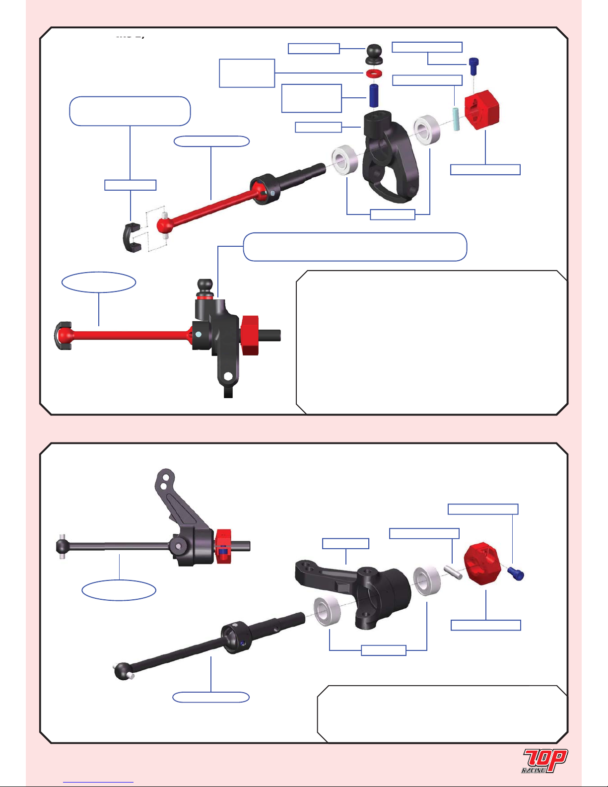
BAG G Mold G-01-1 Steering Block x 2
PO-DT1004RD-A-1 5.2mm Wheel Hub x 2
PO-DT1004RD-B-1 2 x 10mm Wheel Hub Pin x 2
PO-DT1004RD-C-1 M2 Wheel Hub Screw x 2
MR105ZZ-1 5 x 10 x 4mm Bearing x 4
Page 13
STEP 15 (Make 2)
2)
Mold G-02-1
PO-DT1004RD-A-1
PO-DT1004RD-B-1
PO-DT1004RD-C-1
AW-SxxxRD-1
See parts table
for collar size
MR105ZZ-1
PA-HBS003-1
PO-DT0006-1
PA-SS03xxBK-1
See parts table
for set screw
from STEP 14A
Note: Cut any burr
that might exist.
REAR HUB CARRIER ASSEMBLY
STEP 16A (Make 2 for Rubber Asphalt Edition ONLY)
STEERING BLOCK ASSEMBLY
Rubber Foam
BAG G Mold G-02-1 Rear Hub Carrier x 2 x 2
PO-DT1004RD-A-1 5.2mm Wheel Hub x 2 x 2
PO-DT1004RD-B-1 2 x 10mm Wheel Hub Pin x 2 x 2
PO-DT1004RD-C-1 M2 Wheel Hub Screw x 2 x 2
AW-S250RD-1 3 x 5.5 x 2.5mm Collar x 2
AW-S200RD-1 3 x 5.5 x 2.0mm Collar x 2
AW-S200RD-1 3 x 5.5 x 2.0mm Collar x 2
MR105ZZ-1 5 x 10 x 4mm Bearing x 4 x 4
PA-HBS003-1 5.3mm Ball Stud x 2 x 2
PO-DT0006-1 Dog Bone C Drive x 2 x 2
PA-SS0310BK-1 M3x10mm Set Screw x 2
PA-SS0312BK-1 M3x12mm Set Screw x 2
from STEP 14B
PO-DT1004RD-A-1
MR105ZZ-1
PO-DT1004RD-B-1
PO-DT1004RD-C-1
Mold G-01-1
STEP 16A
FINISHED
STEP 15
FINISHED
Note: Use this screw hole instead for the setup of
foam carpet edition, when installing PA-HBS003-1.
Page 14
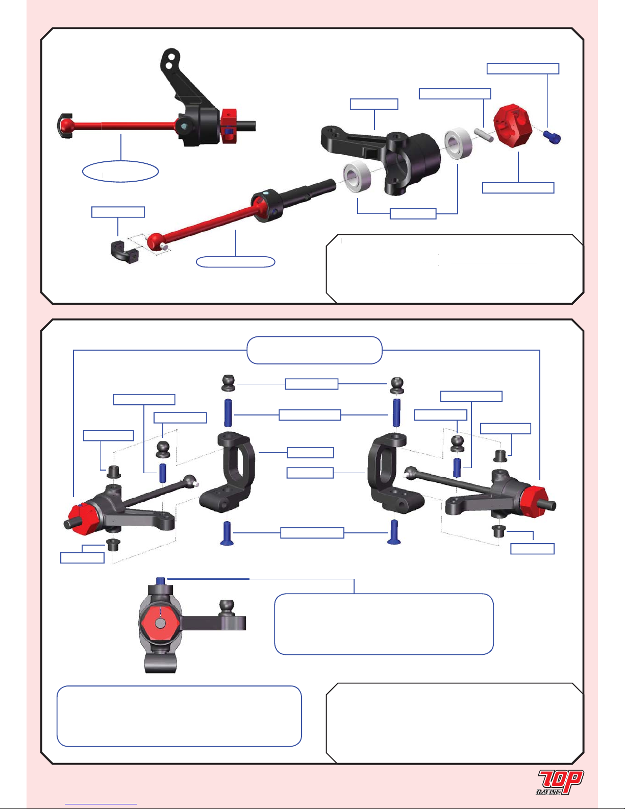
BAG G Mold F-01-1 Left Castor Block - 4 x 1
Mold F-02-1 Right Castor Block - 4 x 1
4152-P4S1-1 Castor Block Insert x 4
PA-HBS003-1 5.3mm Ball (Steel) x 4
PA-SS0312BK-1 M3x12mm Set Screw x 2
PA-SS0308BK-1 M3x8mm Set Screw x 2
PA-CM0310BK-1 M3x10mm Countersunk Screw x 2
Page 14
STEERING BLOCK ASSEMBLY (cont’d)
STEP 17
STEP 16B (Make 2 for Foam Carpet Edition ONLY)
BAG G Mold G-01-1 Steering Block x 2
PO-DT1004RD-A-1 5.2mm Wheel Hub x 2
PO-DT1004RD-B-1 2 x 10mm Wheel Hub Pin x 2
PO-DT1004RD-C-1 M2 Wheel Hub Screw x 2
MR105ZZ-1 5 x 10 x 4mm Bearing x 4
PO-DT0006-1 Dog Bone C Drive x 2
STEP 16B
FINISHED
AG
G
old G-01-
1
teering Block
RD-
A-1
mm
Whe
el
-DT1004RD-B-1 x 10mm Wheel Hub Pinx
2
STEP 16B
FINISHE
D
from STEP 14A
PO-DT1004RD-A-1
MR105ZZ-1
PO-DT1004RD-B-1
PO-DT1004RD-C-1
Mold G-01-1
PO-DT0006-1
Rubber Edition: from STEP 16A
Foam Edition: from STEP 16B
Mold F-01-1
Mold F-02-1
PA-CM0310BK-1
PA-SS0312BK-1
PA-HBS003-1
PA-HBS003-1
PA-HBS003-1
PA-SS0308BK-1
PA-SS0308BK-1
4152-P4S1-1
4152-P4S1-1
4152-P4S1
4152-P4S1
Note: The same steps apply for both rubber and
foam edition. The only difference is the part from STEP
16. The diagram only shows the assembly from STEP
16A for the rubber edition; for foam addition, use the
assembly from STEP 16B instead.
Note: For each steering block assembly,
make sure the set screw thread is exposed by
2.5 to 3.0mm and be sure not to overtighten it
because this would cause the end of the screw to
touch the universal axle.
Page 15
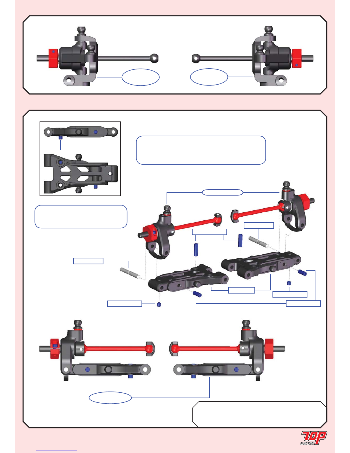
BAG H Mold E-02-1 Rear Suspension Arm x 2
TC-PSU001-1 3mm x 23mm Hinge Pin x 2
PA-SS0306BK-1 M3x6mm Set Screw x 2
PA-SS0308BK-1 M3x8mm Set Screw x 4
Page 15
STEERING BLOCK ASSEMBLY (cont’d)
STEP 18
STEP 17 (cont’d)
REAR SUSPENSION ASSEMBLY
STEP 18
FINISHED
Mold E-02-1
from STEP 15
PA-SS0308BK-1
TC-PSU001-1
TC-PSU001-1
PA-SS0308BK-1
PA-SS0306BK-1
PA-SS0306BK-1
Note: Downstop (droop) level should be adjusted
based on your personal setup preference or according
to the setup sheets on Page 29 for Rubber Asphalt
Edition or Page 30 for Foam Carpet Edition.
Note: For each pivot ball
location make sure the set screw
thread is exposed by 2.5 to 3.0mm.
STEP 17
(Left Side)
FINISHED
STEP 17
(Right Side)
FINISHED
Page 16
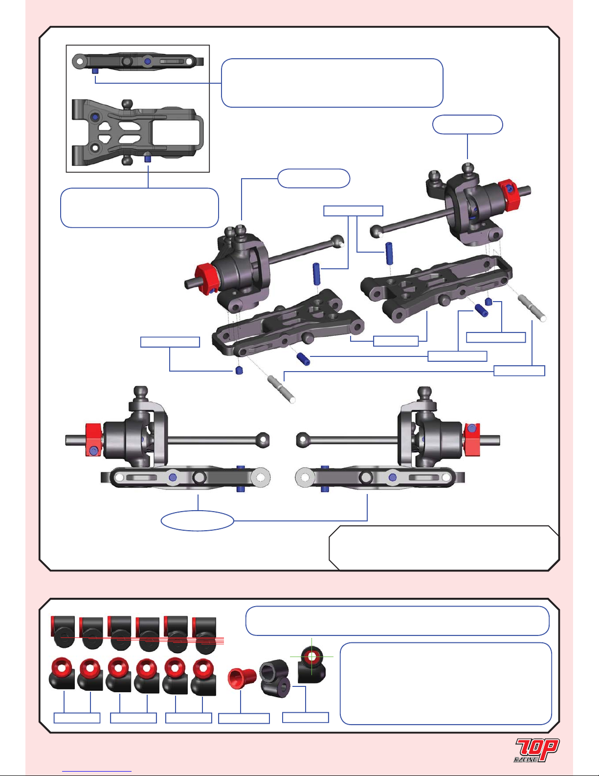
Page 16
STEP 19
FINISHED
FRONT SUSPENSION ASSEMBLY
STEP 19
BAG H Mold E-01-1 Front Suspension Arm x 2
TC-PSU001-1 3mm x 23mm Hinge Pin x 2
PA-SS0306BK-1 M3x6mm Set Screw x 2
PA-SS0308BK-1 M3x8mm Set Screw x 4
from STEP 17
(LEFT SIDE)
TC-PSU001-1
PA-SS0308BK-1
from STEP 17
(RIGHT SIDE)
PA-SS0308BK-1
Mold E-01-1
PA-SS0306BK-1
PA-SS0306BK-1
Note: The alloy suspension mount insert is
off-centered. To rotate the insert up side down
would lower or heighten the suspension mount
by 0.5mm. In combination with the 3 plastic
suspension mounts with increment of 1.0mm,
it would give you 6 steps of suspension mount
height adjustments with 0.5mm increments.
Note: Pay attention to the orientation of the suspension mount inserts
based on your setup. The screw hole is vertically offset by 0.25mm.
SUSPENSION MOUNT
STEP 20
Mold M-02-1
TC-PSU007-1
Mold M-02-1Mold M-01-1 Mold M-03-1
H
H
M
M
L
L
Note: For each pivot ball
location make sure the set screw
thread is exposed by 2.5 to 3.0mm.
Note: Downstop (droop) level should be adjusted
based on your personal setup preference or according
to the setup sheets on Page 29 for Rubber Asphalt
Edition or Page 30 for Foam Carpet Edition.
Page 17
Page 17
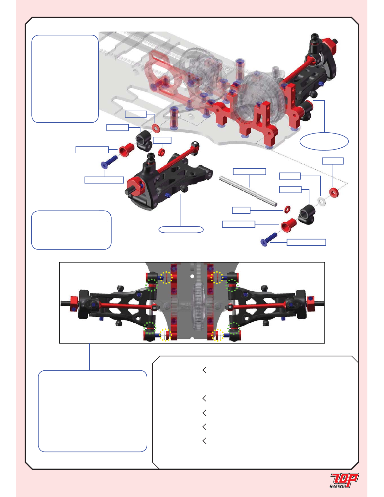
REAR SUSPENSION
STEP 21
Note: This fi gure shows
the assembly of the left-rear
suspension. Assemble the
right-rear suspension in a
symmetrical manner.
Note:
1. The thicknesses and positions of
the large spacers determines tread
width and toe angle (marked by “yellow
dots”).
2. The thicknesses and positions of
the small spacers determine the wheel
base in the forward/rearward direction
(marked by “green dots”).
*Refer to the setup sheets for more
details.
ear
the
a
PA-CM0314BK-1
TC-PSU002-1
TC-PSU007-1
*ARM4
*ARM3
TC-PSU007-1
*SUSMR
*SUSMR
*SUS4/2
*SUS3/1
*SUS4/1
from STEP 18
STEP 21
(RIGHT SIDE)
FINISHED
PA-CM0316BK-1
Rubber Foam
BAG H
*SUSMR
Mold M-02-1 Suspension Mount M - MRC
x 4
Mold M-03-1 Suspension Mount L - LRC x 4
TC-PSU007-1 Suspension Mount Insert x 4 x 4
TC-PSU002-1 3mm x 51mm Hinge Pin x 2 x 2
*SUS3/1
AW-M100RD-1 Large 3mm Spacer (t = 1.0mm)
x 2
AW-M100RD-1 Large 3mm Spacer (t = 1.0mm) x 2
*SUS4/1
AW-M300RD-1 Large 3mm Spacer (t = 3.0mm) x 2
AW-M300RD-1 Large 3mm Spacer (t = 3.0mm) x 2
*SUS4/2
AW-M040SV-1 Large 3mm Spacer (t = 0.4mm) x 2
AW-M040SV-1 Large 3mm Spacer (t = 0.4mm) x 2
*ARM3
AW-S150RD-1 3 x 5.5 x 1.5mm Collar x 2
AW-S200RD-1 3 x 5.5 x 2.0mm Collar x 2 x 2
*ARM4 AW-S150RD-1 3 x 5.5 x 1.5mm Collar x 2
PA-CM0314BK-1 M3x14mm Countersunk Screw x 2 x 2
PA-CM0316BK-1 M3x16mm Countersunk Screw x 2 x 2
Note: Pay special
attention to the
orientation of TCPSU007 according
to the standard setup
sheet for rubber asphalt
and foam carpet
edition. Refer to page
15 to understand how
the orientation affects
suspension mount
height.
Page 18
Rubber Foam
BAG H
*SUSMF
Mold M-02-1 Suspension Mount B - MRC x 4
Mold M-02-1 Suspension Mount B - MRC x 4
TC-PSU007-1 Suspension Mount Insert x 4 x 4
TC-PSU002-1 3mm x 51mm Hinge Pin x 2 x 2
*SUS1/1
AW-M100RD-1 Large 3mm Spacer (t = 1.0mm)
x 2
AW-M080SV-1 Large 3mm Spacer (t = 0.8mm) x 2
*SUS2/1 AW-M100RD-1 Large 3mm Spacer (t = 1.0mm) x 2
*ARM1
AW-S150RD-1 3 x 5.5 x 1.5mm Collar x 2
AW-S150RD-1 3 x 5.5 x 1.5mm Collar x 2
*ARM2
AW-S150RD-1 3 x 5.5 x 1.5mm Collar x 2
AW-S150RD-1 3 x 5.5 x 1.5mm Collar x 2
PA-CM0314BK-1 M3x14mm Countersunk Screw x 4 x 4
PA-CM0316BK-1 M3x16mm Countersunk Screw
Page 18
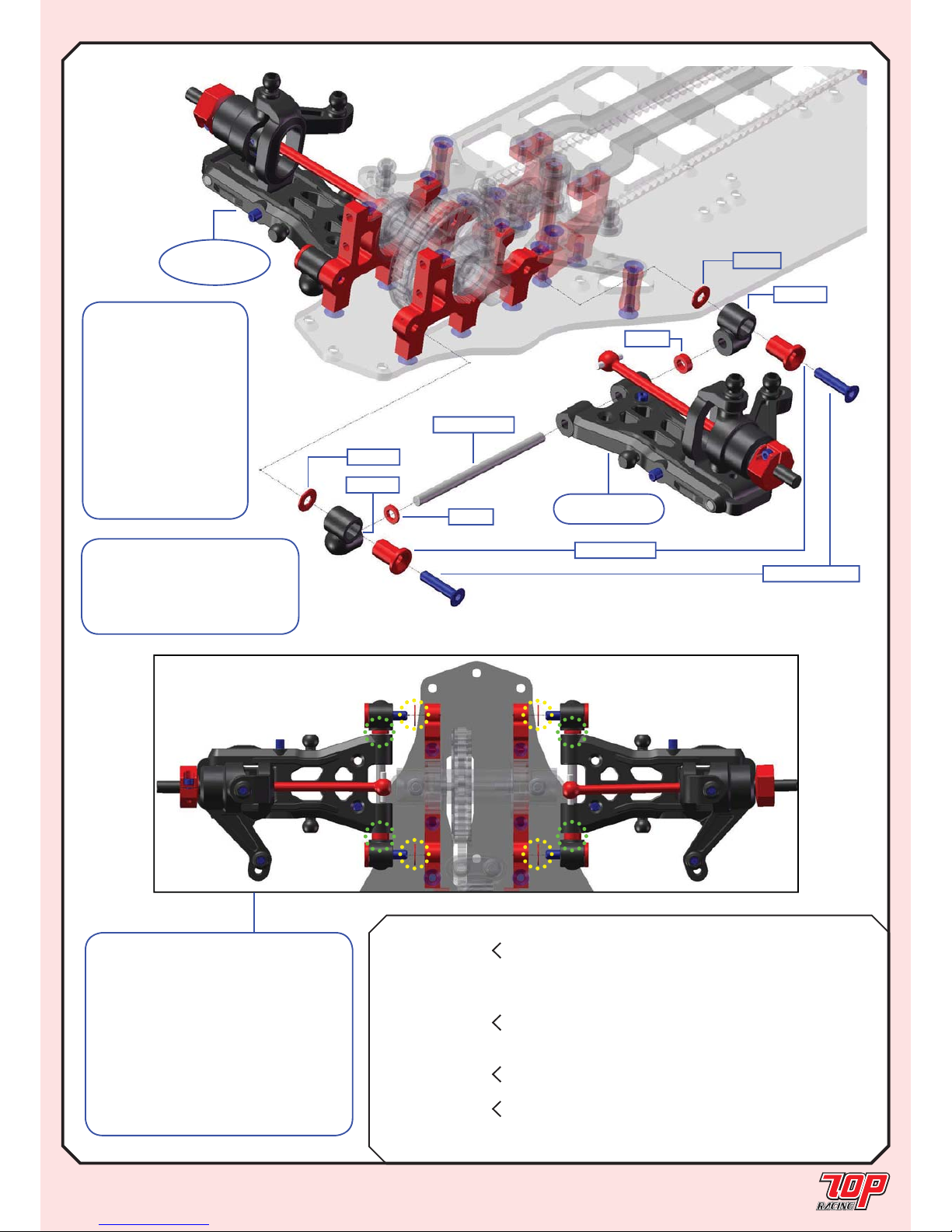
FRONT SUSPENSION
STEP 22
Note:
1. The thicknesses and positions of
the large spacers determines tread
width and toe angle (marked by “yellow
dots”).
2. The thicknesses and positions of
the small spacers determine the wheel
base in the foward/rearward direction
(marked by “green dots”).
*Refer to the setup sheet for more
details.
PA-CM0314BK-1
TC-PSU002-1
*ARM1
*ARM2
TC-PSU007-1
*SUSMF
*SUSMF
*SUS1/1
from STEP 19
Left Side
STEP 22
(RIGHT SIDE)
FINISHED
SUS2/1
Note: The fi gure shows
the assembly of the left-front
suspension. Assemble the
right-front suspension in a
symmetrical manner.
Note: Pay special
attention to the
orientation of TCPSU007 according
to the standard setup
sheet for rubber asphalt
and foam carpet
edition. Refer to page
15 to understand how
the orientation affects
suspension mount
height.
Page 19
BAG I Mold H-02-1 Ball Cup - 14.5mm x 10
Mold H-03-1 Ball Cup - 18.5mm x 4
TC-PSU005-1 3mm x 30mm Tie Rod (Steel) x 7
Page 19
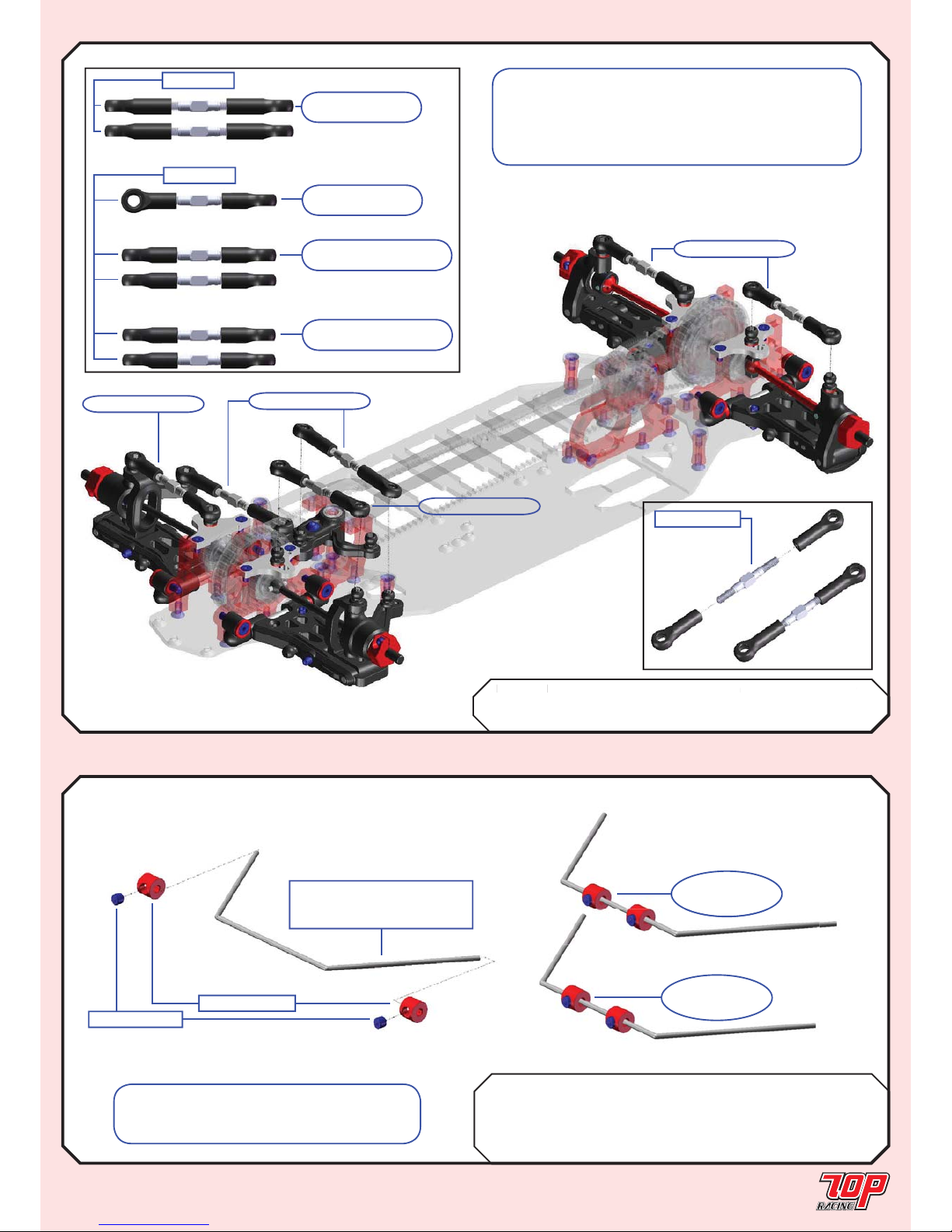
LINKAGE
STEP 23
Rubber Foam
BAG I TC-PSB012-1 1.2mm Stabilizer Bar x 2
TC-PSB014-1 1.4mm Stabilizer Bar x 1
AW-ST01RD-A-1 Aluminum Stopper (Red) x 4 x 2
PA-SS0303BK-1 M3x3mm Set Screw x 4 x 2
STABILIZER BAR
AG
I
old H-02-
1
all
C
up
- 14.5
x
10
from STEP 23A
from STEP 23C
from STEP 23D
from STEP 23C
STEP 24
TC-PSU005-1*
STEP 23A
Steering Tie Rod
STEP 23C
Front Camber Tie Rod
STEP 23D
Rear Camber Tie Rod
STEP 23B
Servo Tie Rod
Mold H-02-1
Mold H-03-1
PA-SS0303BK-1
Rubber Edition: TC-PSB012-1
Foam Edition: TC-PSB014-1
AW-ST01RD-A-1
STEP 24
(Rubber)
FINISHED
STEP 24
(Foam)
FINISHED
Note: Make 2 sets of stabilizer bar
assembly (1.2mm) for rubber version and 1
set of (1.4mm) for foam version.
Note: Tie Rod lengths are not shown in scale.
Please adjust length according to the standard setups
on page 27 for STEP 23B(servo tie rod adjustment)
and page 29-30 for STEP 23A, C and D (camber and
toe angle adjustments).
Page 20
Rubber Foam
BAG I Mold H-01-1 Ball Cup - 10.5mm x 4 x 2
Mold H-02-1 Ball Cup - 14.5mm x 4 x 2
TC-PSU003RD-1 Threaded Sway Bar Adjuster x 4 x 2
PA-HBS003-1 5.3mm Ball (Steel) x 4 x 2
AW-S250RD-1 3 x 5.5 x 2.5mm Collar (Red) x 4 x 2
PA-SS0310BK-1 M3x10mm Set Screw x 4 x 2
Page 20
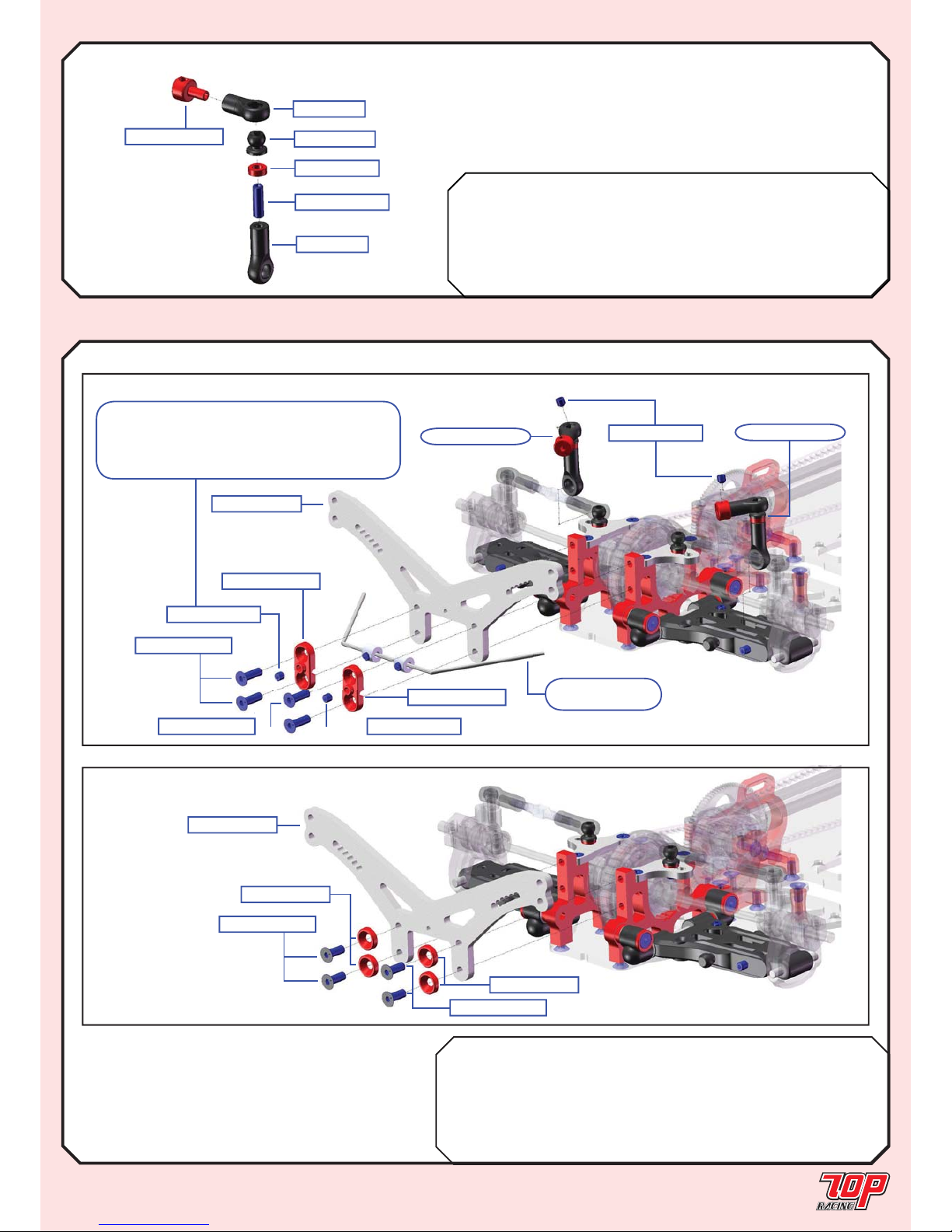
STABILIZER LINK
STEP 25 (Rubber Asphalt Edition - Make 4; Foam Carpet Edition - Make 2)
Rubber Foam
BAG I TC-PCHS007-1 Rear Shock Tower (3.0mm) x 1 x 1
TC-PSU006RD-1 Stabilizer Mount x 2
PA-SS0303BK-1 M3x3mm Set Screw x 4
PA-CM0310BK-1 M3x10mm Countersunk Screw x 4
AW-BW32RD-1 Large Bevel Washer (Red) x 4
PA-CM0308BK-1 M3x8mm Countersunk Screw x 4
SHOCK TOWERS (REAR)
STEP 26
TC-PSU003RD-1
Mold H-01-1
TC-HBS003-1
AW-S250RD-1
PA-SS0310BK-1
Mold H-02-1
Foam Carpet Edition
PA-CM0308BK-1
TC-PCHS007-1
PA-CM0308BK-1
AW-BW32RD-1
AW-BW32RD-1
from STEP 24
(Rubber)
Rubber Asphalt Edition
TC-PCHS007-1
PA-CM0310BK-1
PA-CM0310BK-1
PA-SS0303BK-1
PA-SS0303BK-1
TC-PSU006RD-1
TC-PSU006RD-1
PA-SS0303BK-1
from STEP 25
from STEP 25
Note: Apply small amount of Locktite
at M3x3 set screw to secure it from its
position inside the stabilizer mount to hold the
stabilizer bar in place without loosening.
Page 21
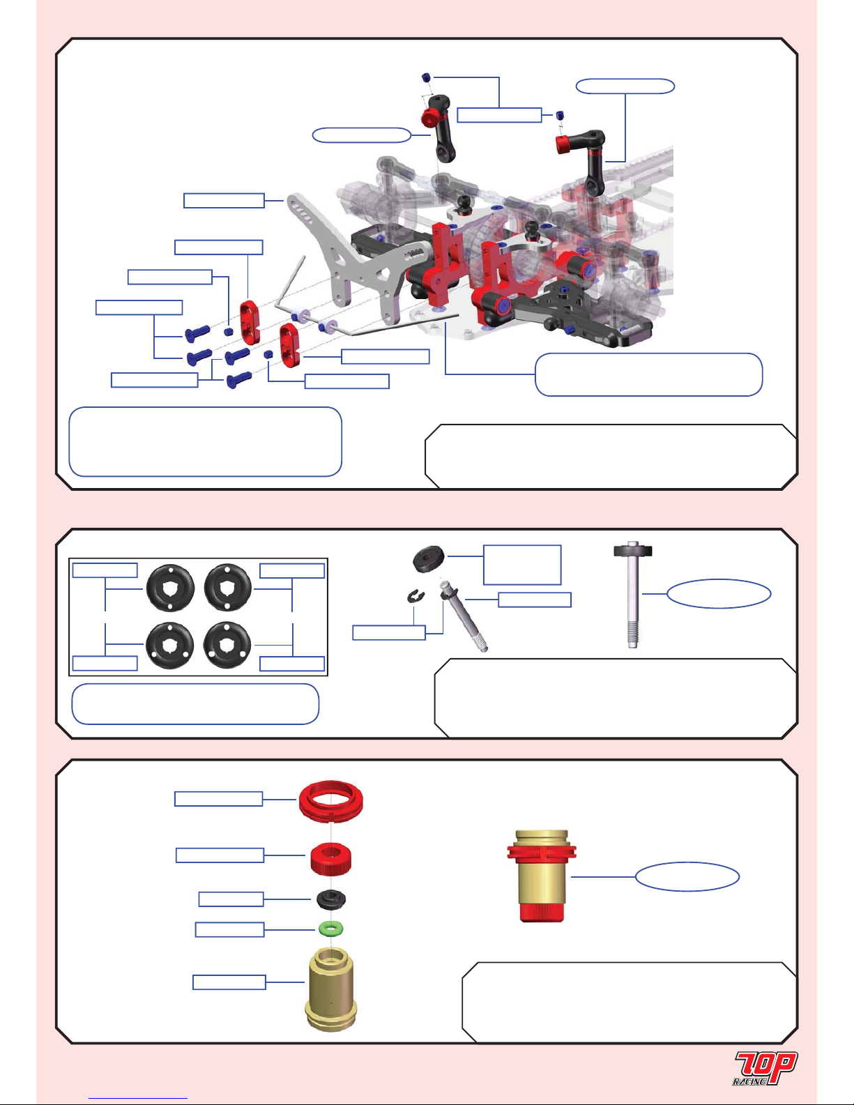
Page 21
SHOCK TOWERS (FRONT)
STEP 27
BAG I TC-PCHS006-1 Front Shock Tower (3.0mm) x 1
TC-PSU006RD-1 Stabilizer Mount x 2
PA-SS0303BK-1 M3x3mm Set Screw x 4
PA-CM0310BK-1 M3x10mm Countersunk Screw x 4
SHOCKS
STEP 28 (Make 4)
TC-PCHS006-1
PA-CM0310BK-1
PA-CM0310BK-1
PA-SS0303BK-1
PA-SS0303BK-1
TC-PSU006RD-1
TC-PSU006RD-1
PA-SS0303BK-1
from STEP 25
from STEP 25
Rubber Edition: from STEP 24 (Rubber)
Foam Edition: from STEP 04 (Foam)
Rubber Foam
BAG J Mold R-01-1 Shock Piston 1.0 - 3 hole x 4
Mold-R-02-1 Shock Piston 1.2 - 3 hole x 4
TC-PSH007-1 Shock Shaft x 4 x 4
PA-ER0020-1 E-Clip x 8 x 8
BAG J TC-PSH004-1 Shock Body x 4
TC-PSH006RD-1 Shock Bottom x 4
TC-PSH003RD-1 Shock Spring Adjuster x 4
Mold R-05-1 Damper O-Ring Holder x 4
PP-010320-1 3mm Silicon O-ring x 4
STEP 29 (Make 4)
Mold R-0x-1
See parts table
for piston size
TC-PSH007-1
TC-PSH007-1
STEP 28
FINISHED
TC-PSH003RD-1
TC-PSH006RD-1
Mold R-05-1
PP-010320-1
TC-PSH004-1
STEP 29
FINISHED
Note: Y ou could choose from a variety
of shock piston to suit your needs.
Mold R-03-1
Mold R-01-1
Mold R-04-1
Mold R-02-1
1.2mm hole
1.0mm hole
Note: Apply small amount of Locktite
at M3x3 set screw to secure it from its
position inside the stabilizer mount to hold the
stabilizer bar in place without loosening.
Page 22
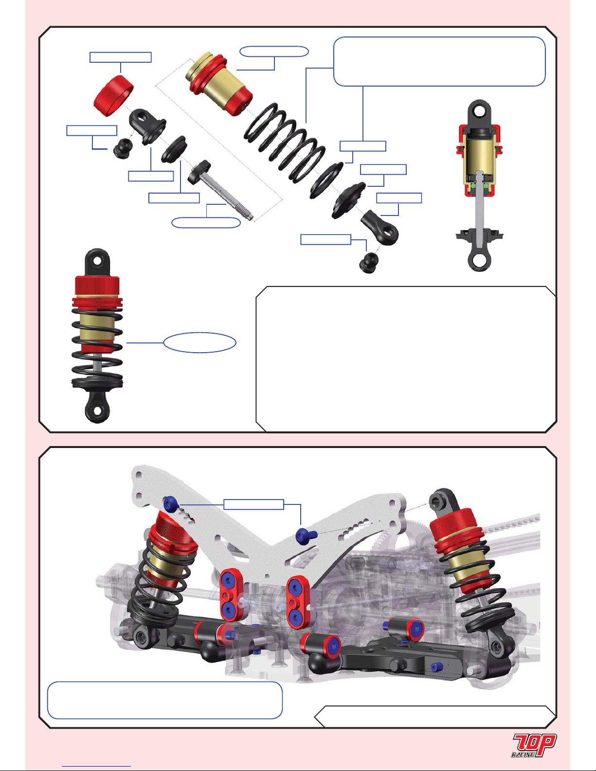
Page 22
SHOCKS (cont’d)
STEP 30 (Make 4)
Rubber Foam
FRFR
BAG J Mold H-01-1 Ball Cup - 10.5mm x 2 x 2 x 2 x 2
Mold H-04-1 Damper Top Ring (Shock Top) x 2 x 2 x 2 x 2
Mold M-04-1 Damper Spring Holder x 2 x 2 x 2 x 2
Mold M-05-1 Spring Adjust Nut Spacer - 14mm x 2 x 2
TC-PSH002-1 Shock Bladder x 2 x 2 x 2 x 2
TC-PSH005RD-1 Shock Cap x 2 x 2 x 2 x 2
PA-HBS003-1 5.3mm Ball (Steel) x 4 x 4 x 4 x 4
PS-TR15600 Shock Spring (14 x 1.5 x 6.00) x 2
PS-TR15650 Shock Spring (14 x 1.5 x 6.50) x 2
PS-TF17675 Shock Spring (13 x 1.7 x 6.75) x 2
PS-TF14625 Shock Spring (13 x 1.4 x 6.25) x 2
STEP 30
FINISHED
STEP 31 (REAR)
BAG J PA-BM0306BK-1 M3x6mm Button Head Screw x 2
TC-PSH005RD-1
PA-HBS003-1
Mold H-04-1
TC-PSH002-1
from STEP 28
from STEP 29
Mold M-05-1
Mold M-04-1
Mold H-01-1
PA-HBS003-1
Note: Read the parts table very carefully to
correctly locate different parts for the front and
rear shocks of rubber asphalt edition and foam
carpet edition, respectively.
PA-BM0306BK-1
Note: Please follow the standard setup sheets on
pages 29-30 as inital setups for shock locations of rubber
asphalt edition and foam carpet edition, respectively.
Page 23
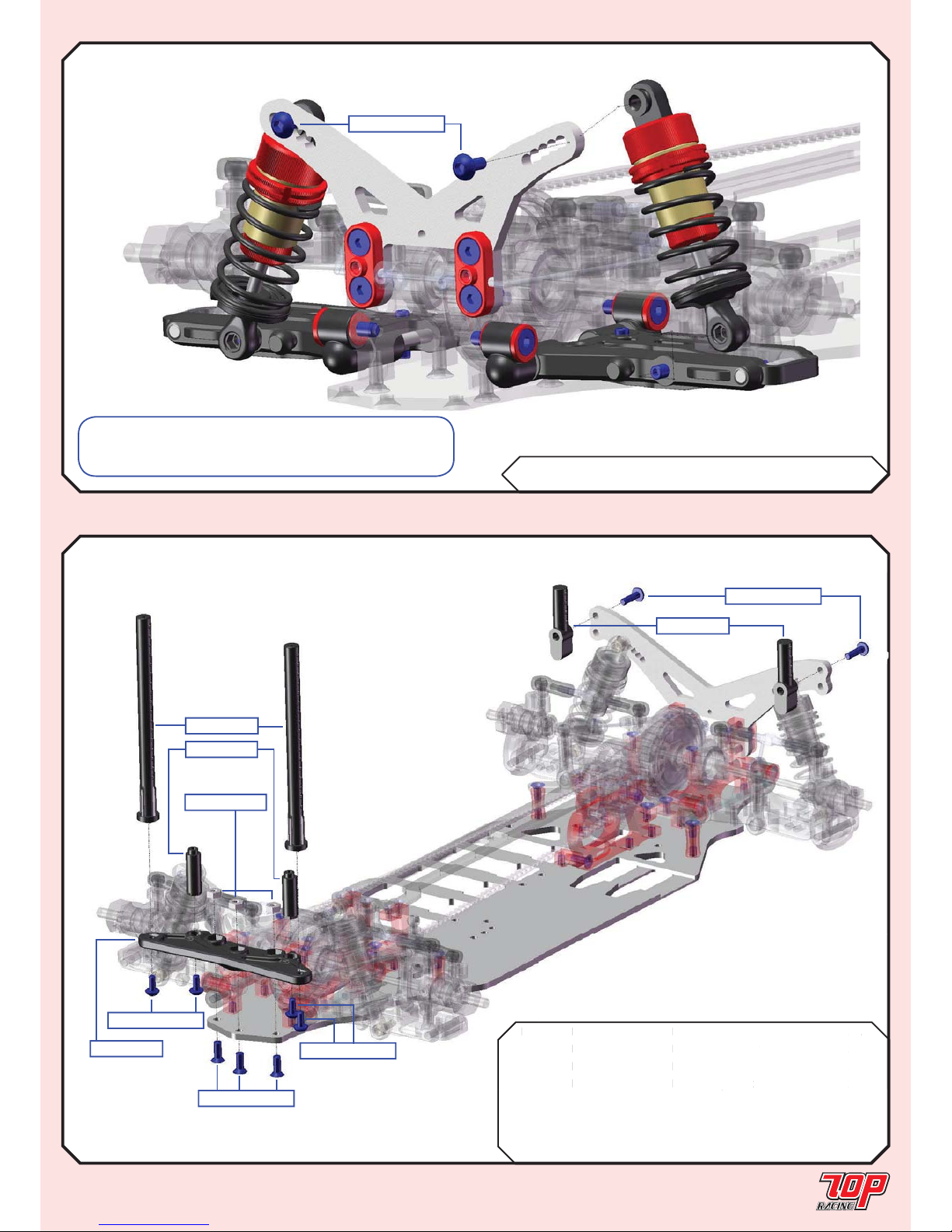
Page 23
SHOCKS (cont’d)
STEP 32 (Front)
STEP 33
BAG K Mold Q-01-1 Lower Bumper - Photon x 1
Mold D-03-1 Bumper Standoff x 2
Mold D-04-1 Front Body Post x 2
Mold D-05-1 Rear Body Post x 2
PA-BM0306BK-1 M3x6mm Button Head Screw x 4
PA-BM0310BK-1 M3x10mm Button Head Screw x 2
PA-CM0308BK-1 M3x8mm Countersunk Screw x 3
PA-FN00M3-1 M3 Nut x 3
BAG J PA-BM0306BK-1 M3x6mm Button Head Screw x 2
PA-BM0306BK-1
BUMPER & BODY POSTS
Note: Please follow the standard setup sheets on
pages 29-30 as inital setups for shock locations of rubber
asphalt edition and foam carpet edition, respectively.
AG
K
old Q-01
-1
ower Bumper - Photo
n
-03
Bumper Stando
ff
old D-04-
1
ront Body Pos
t
x
2
ld D-05-
1
ear Body Pos
t
x
2
Mold Q-01-1
PA-BM0306BK-1
PA-BM0306BK-1
PA-CM0308BK-1
Mold D-03-1
Mold D-04-1
Mold D-05-1
PA-BM0310BK-1
PA-FN00M3-1
Page 24
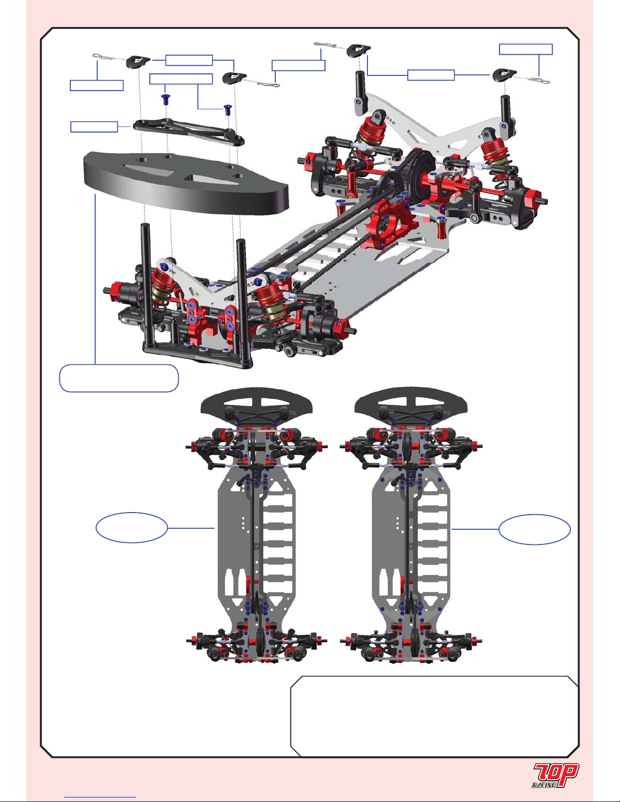
Page 24
BUMPER & BODY POSTS (cont’d)
STEP 34
Rubber Foam
BAG K Mold D-02-1 Upper Bumper x 1 x 1
Mold D-07-1 Body Holder x 4 x 4
TC-PCH20R-1 Foam Bumper - Rubber Spec. x 1
TC-PCH20F-1 Foam Bumper - Foam Spec. x 1
PA-BPS3SV-1 Body Clips x 4 x 4
PA-CM0308BK-1 M3x8mm Countersunk Screw x 2 x 2
STEP 34
(Rubber Edition)
FINISHED
STEP 34
(Foam Edition)
FINISHED
3
4
Mold D-02-1
Mold D-07-1
Mold D-07-1
PA-BPS3SV-1
PA-BPS3SV-1
PA-BPS3SV-1
PA-CM0308BK-1
Rubber Edition: TC-PCH20R-1
Foam Edition: TC-PCH20F-1
Page 25
Page 25
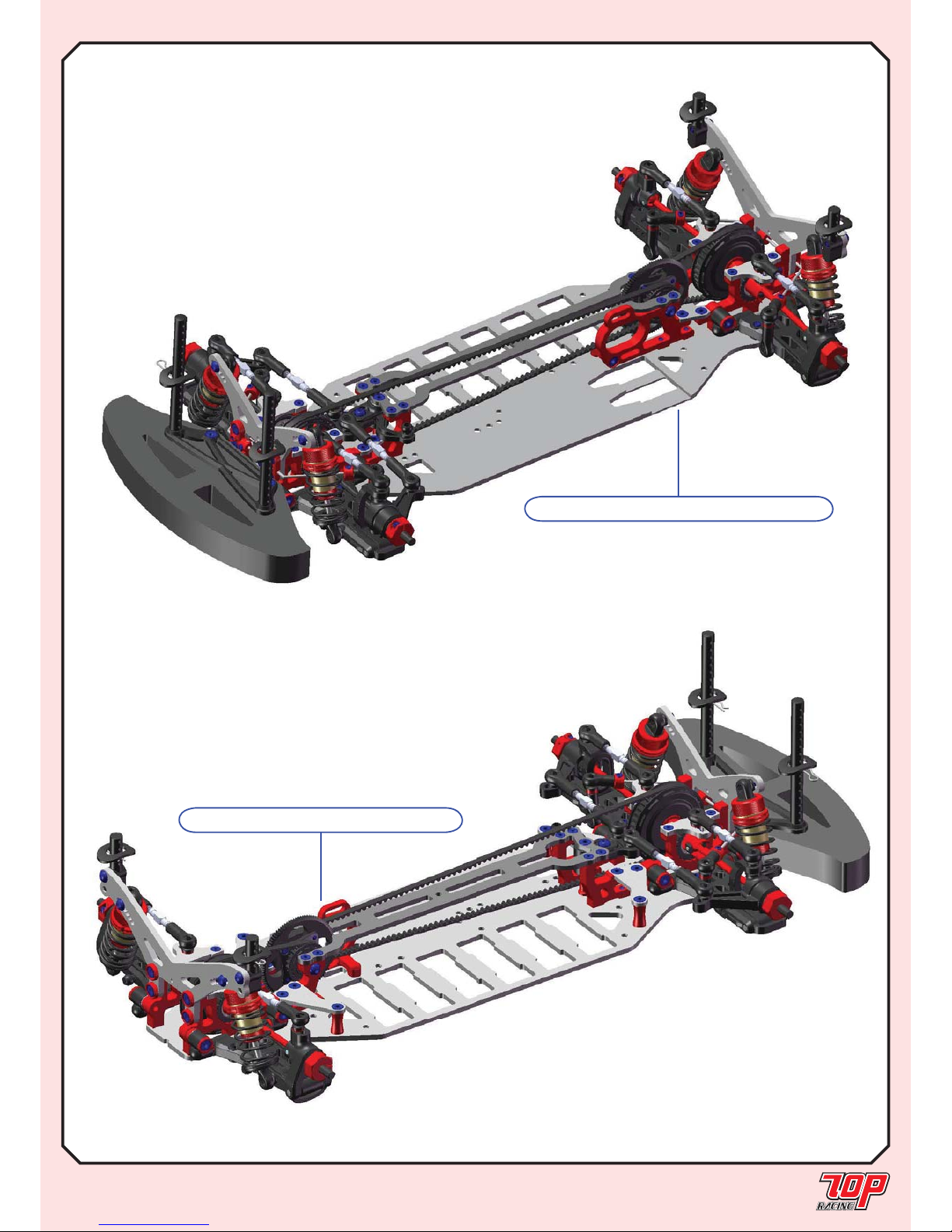
RUBBER ASPHALT EDITION VS. CARPET FOAM EDITION
STEP 34 (Finished)
PHOTON: RUBBER ASPHALT EDITION
PHOTON: FOAM CARPET EDITION
Page 26
Mold N-02-1
Mold N-01-1
Mold N-03-1
Mold N-04-1
PA-FN00M3-1
PA-FN00M3-1
Mold N-03-1
PA-BM0306BK-1
PA-BM0306BK-1
PA-CM0306BK-1
PA-CM0310BK-1
PA-CM0310BK-1
Page 26
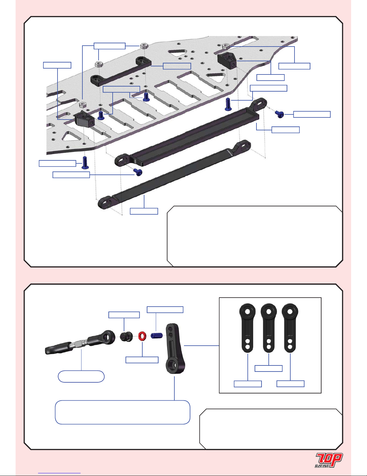
LIPO / SUB-C BATTERY GUARD & WEIGHT TRAY
STEP 35
LiPo Sub-C
BAG K Mold N-01-1 Lipo Battery Brace x 1
Mold N-02-1 Sub-C Battery Brace x 1
Mold N-03-1 Lipo Mount x 2 x 2
Mold N-04-1 Lipo Positioner x 1 x 1
PA-FN00M3-1 M3 Nut x 4 x 4
PA-BM0306BK-1 M3x6mm Button Head Screw x 2 x 2
PA-CM0306BK-1 M3x6mm Countersunk Screw x 2 x 2
PA-CM0310BK-1 M3x10mm Countersunk Screw x 2 x 2
SERVO HORN & LINKAGE
STEP 36
BAG L Mold P-01-1 Servo Arm - Futaba x 1
Mold P-02-1 Servo Arm - Hitech x 1
Mold P-03-1 Servo Arm - KO/Sanwa x 1
PA-HBS003-1 5.3mm Ball (Steel) x 1
AW-S100RD-1 3 x 5.5 x 1.0mm Collar x 1
PA-SS0308BK-1 M3x8mm Set Screw x 1
STEP 23B
Servo Tie Rod
PA-HBS003-1
AW-S100RD-1
PA-SS0308BK-1
Mold P-01-1
Mold P-02-1
Mold P-03-1
FKH
Note: Choose the correct servo arm for your
servo arm manufacturer. Refer to the part list and
fi gure on your right.
Page 27
from STEP 36
PA-BM0306BK-1
Mold P-04-1
Mold P-04-1
AW-BW31RD-1
PA-CM0308BK-1
PA-CM0306BK-1
Page 27
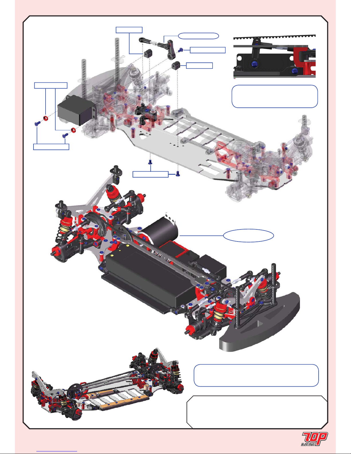
SERVO ARM & LINKAGE (cont’d)
STEP 37
BAG L Mold P-04-1 Servo Mount - Large x 2
AW-BW31RD-1 Bevel Washer (Red) x 2
PA-BM0306BK-1 M3x6mm Button Head Screw x 1
PA-CM0306BK-1 M3x6mm Countersunk Screw x 2
PA-CM0308BK-1 M3x8mm Countersunk Screw x 2
Note: The servo tie rod should
form a right angle with the servo
arm for proper steering balance.
Note: The fi gure on the left shows the Photon
with our customized brass balancing weight.
These are purchased separately.
A-CM
0306
BK-
1
Your Photon
is ready to race!!
Page 28
Page 28
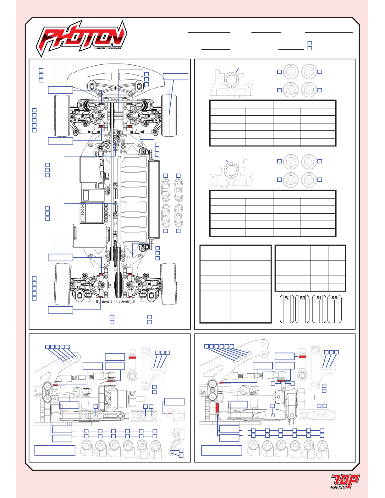
PHOTON SETUP RECORD
MOTOR
SPUR GEAR
PINION GEAR
BATTERY
BODY SHELLS
WING
ESC SETTING
FRONT REAR
BRAND
COMPOUND
INSERT
WHEEL
TIRE TREATMENT
654321
mm
321
H
H
M
M
L
L
RF
RR
mm
mm
mm mm
2 3 1
mm
Standard
Optional
CAMBER PLATE
Toe-In = (RR-RF) / 0.8
= deg
FRONT REAR
REAR MEASUREMENTS REAR SHOCKS
RIDE HEIGHT mm OIL WEIGHT wt
CAMBER ANGLE deg PISTON Standard/Optional
DROOP mm BLADDER
WHEEL HUBS mm SPRING
WHEEL SPACER mm NOTE
1.2mm
2 holes
1.2mm
3 holes
1.0mm
2 holes
1.0mm
3 holes
MARK POSITION
FRONT MEASUREMENTS FRONT SHOCKS
RIDE HEIGHT mm OIL WEIGHT wt
CAMBER ANGLE deg PISTON Standard/Optional
DROOP mm BLADDER
WHEEL HUBS mm SPRING
WHEEL SPACER mm NOTE
MARK POSITION
1.2mm
2 holes
1.2mm
3 holes
1.0mm
2 holes
1.0mm
3 holes
Name: Date: Track:
Temperature: Condition:
Rubber Asphalt Edition
Foam Carpet Edition
54321
mm
321
H
H
M
M
L
L
FF
FR
mm
mm
mm mm
2
3 1
mm
Standard
Optional
CAMBER PLATE
Toe-Out = (FF-FR) / 0.8
= deg
mm
FF mm
FR mm
RF mm
RR mm
Rubber Asphalt
Carpet Foam
Other ________
TOP DECK
Rubber Asphalt
Carpet Foam
Other ________
FRONT WING
Rubber Asphalt
Carpet Foam
Other ________
REAR WING
VERTICAL
ACKERMANN
Forward
Middle
Rearward
RADIAL
ACKERMANN
FRONT DRIVE
Spool
Diff.
One-Way
TOE deg
FRONT DIFF.
TENSION
Tight
Medium
Loose
REAR DIFF.
TENSION
Tight
Medium
Loose
CASTOR
4-deg
8-deg
6-deg
Original
Alloy
STEERING BLOCK
Original
Alloy
REAR HUB CARRIER
Page 29
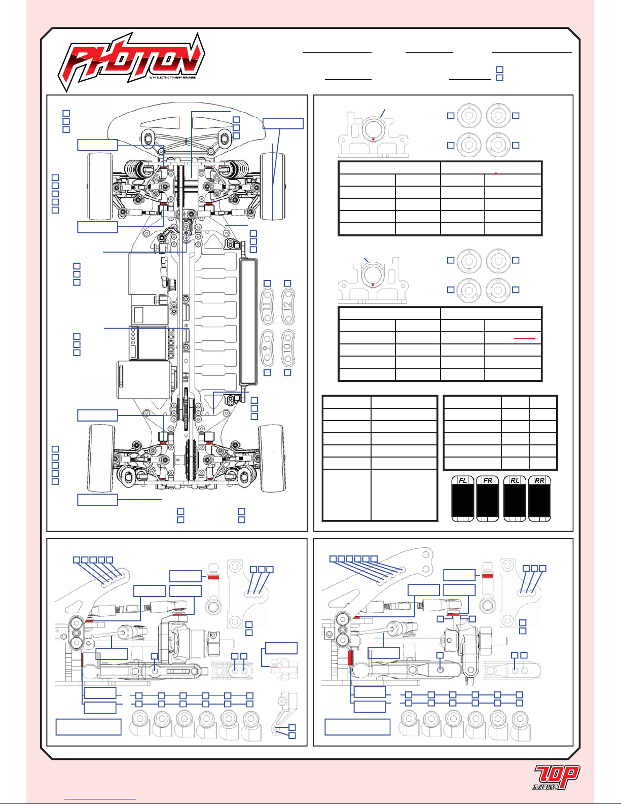
Page 29
PHOTON SETUP RECORD
X
654321
2.5 mm
X
321
H
H
M
M
L
L
X
X
RF
RR
1.0 mm
3.4 mm
2.5 mm1.5 mm
X
2 3 1
X
1.2 mm
StandardX
Optional
CAMBER PLATE
Toe-In = (RR-RF) / 0.8
3.0 = 3.0 deg
FRONT REAR
Name: Date: Track: Rubber Std. Setup
Temperature: Condition:
Rubber Asphalt Edition
X
Foam Carpet Edition
X
54321
2.5 mm
X
321
H
H
M
M
L
L
X
X
FF
FR
0.8 mm
0.0 mm
0.0 mm2.5 mm
X
2
3 1
1.2 mm
StandardX
Optional
CAMBER PLATE
Toe-Out = (FF-FR) / 0.8
1.0 = 1.0 deg
X
0.0 mm
FF 1.5 mm
FR 1.5 mm
RF 2.0 mm
RR 1.5 mm
Rubber AsphaltX
Carpet Foam
Other ________
TOP DECK
Rubber Asphalt
X
Carpet Foam
Other ________
FRONT WING
Rubber AsphaltX
Carpet Foam
Other ________
REAR WING
VERTICAL
ACKERMANN
Forward
Middle
X Rearward
X
RADIAL
ACKERMANN
FRONT DRIVE
Spool
X
Diff.
One-Way
TOE 0.5 deg
FRONT DIFF.
TENSION
Tight
Medium
Loose
X
REAR DIFF.
TENSION
Tight
Medium
Loose
CASTOR
X 4-deg
8-deg
6-deg
Original
X
Alloy
STEERING BLOCK
Original
X
Alloy
REAR HUB CARRIER
MOTOR
SPUR GEAR
PINION GEAR
BATTERY 7.4V 5000mAh 40C
BODY SHELLS PF Mazda Speed 6
WING STD.
ESC SETTING
FRONT REAR
BRAND Sorex Sorex
COMPOUND 36R 36R
INSERT HaraV3 HaraV3
WHEEL Solaris Solaris
TIRE TREATMENT FX-II FX-II
REAR MEASUREMENTS REAR SHOCKS
RIDE HEIGHT
5.0 mm OIL WEIGHT 40 wt
CAMBER ANGLE 1.5 deg PISTON Standard/Optional
DROOP 5.5 mm BLADDER STD.
WHEEL HUBS STD 5.2 mm SPRING 14mm 1.5 x 6.50
WHEEL SPACER 1.0 mm NOTE
1.2mm
2 holes
1.2mm
3 holes
X
1.0mm
2 holes
1.0mm
3 holes
MARK POSITION
FRONT MEASUREMENTS FRONT SHOCKS
RIDE HEIGHT 5.0 mm OIL WEIGHT 40 wt
CAMBER ANGLE
1.5 deg PISTON Standard/Optional
DROOP 5.5 mm BLADDER STD.
WHEEL HUBS STD 5.2 mm SPRING 14mm 1.5 x 6.00
WHEEL SPACER 0.5 mm NOTE
MARK POSITION
1.2mm
2 holes
1.2mm
3 holes
X
1.0mm
2 holes
1.0mm
3 holes
Page 30
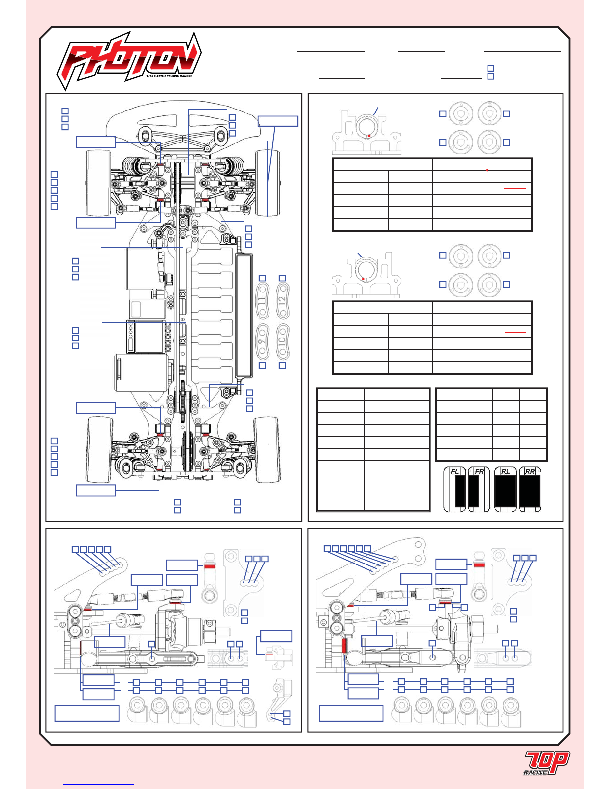
Page 30
PHOTON SETUP RECORD
X
654321
N/A mm
X
321
H
H
M
M
L
L
X
X
RF
RR
1.0 mm
3.4 mm
4.0 mm2.0 mm
2 3X1
X
mm
StandardX
Optional
CAMBER PLATE
Toe-In = (RR-RF) / 0.8
3.0 = 3.0 deg
FRONT REAR
Name: Date: Track: Foam Std. Setup
Temperature: Condition:
Rubber Asphalt Edition
X Foam Carpet Edition
X
54321
2.5 mm
X
321
H
H
M
M
L
L
X
X
FF
FR
1.0 mm
1.0 mm
0.0 mm2.0 mm
X
2
3 1
1.4 mm
StandardX
Optional
CAMBER PLATE
Toe-Out = (FF-FR) / 0.8
0.0 = 0.0 deg
X
1.0 mm
FF 1.5 mm
FR 1.5 mm
RF 3.5 mm
RR 0.0 mm
Rubber Asphalt
X Carpet Foam
Other ________
TOP DECK
Rubber Asphalt
X Carpet Foam
Other ________
FRONT WING
Rubber Asphalt
X Carpet Foam
Other ________
REAR WING
VERTICAL
ACKERMANN
Forward
Middle
X Rearward
X
RADIAL
ACKERMANN
FRONT DRIVE
Spool
X Diff.
One-Way
TOE 1.0 deg
X
FRONT DIFF.
TENSION
Tight
Medium
Loose
X
REAR DIFF.
TENSION
Tight
Medium
Loose
CASTOR
X 4-deg
8-deg
6-deg
Original
X
Alloy
STEERING BLOCK
Original
X
Alloy
REAR HUB CARRIER
MOTOR 4.5 BL
SPUR GEAR 64P-112T
PINION GEAR 64P-25T
BATTERY 7.4V LiPo
BODY SHELLS R9F
WING STD.
ESC SETTING KO Propo 1.5
FRONT REAR
BRAND Jaco Jaco
COMPOUND MAG. MAG.
INSERT N/A N/A
WHEEL N/A N/A
TIRE TREATMENT Jack Jack
REAR MEASUREMENTS REAR SHOCKS
RIDE HEIGHT
4.5 mm OIL WEIGHT 40 wt
CAMBER ANGLE 3.0 deg PISTON Standard/Optional
DROOP 5.0 mm BLADDER STD.
WHEEL HUBS STD 5.2 mm SPRING 13mm 1.4 x 6.25
WHEEL SPACER 0.0 mm NOTE
1.2mm
2 holes
X
1.2mm
3 holes
1.0mm
2 holes
1.0mm
3 holes
MARK POSITION
FRONT MEASUREMENTS FRONT SHOCKS
RIDE HEIGHT 4.2 mm OIL WEIGHT 60 wt
CAMBER ANGLE
2.5 deg PISTON Standard/Optional
DROOP 5.0 mm BLADDER STD.
WHEEL HUBS STD 5.2 mm SPRING 13mm 1.7 x 6.75
WHEEL SPACER 1.0 mm NOTE
MARK POSITION
1.2mm
2 holes
X
1.2mm
3 holes
1.0mm
2 holes
1.0mm
3 holes
Page 31
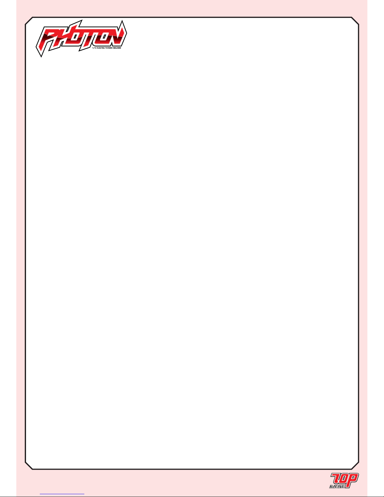
Page 31
STANDARD SPARE PARTS AND OPTIONAL PARTS LIST
STANDARD SPARE PARTS
Kit
TC-PRK001 Photon 1/10 Rubber Edition
TC-PFK001 Photon 1/10 Foam Edition
Chassis
TC-PCH011RD Bulkhead (Red)
TC-PCH012RD Steering Mount Plate (Red)
TC-PCH013RD Motor Plate (Red)
TC-PCH014RD Motor Plate Support (Red)
TC-PCH015RD Mount Plate (Red)
TC-PCH016RD Standoff Post (Red) (2 pcs) - Foam Std.
TC-PCH017RD Steering Post (Red)
TC-PCH20F Foam Bumper - Foam Standard
TC-PCH20R Foam Bumper - Rubber Std.
TC-PCHC01 6-Cell Chassis 2.5mm - Rubber Std.
TC-PCHC04 Top Deck Soft 2.0mm - Rubber Std.
TC-PCHC08 Camber Link Plate 2.5mm
TC-PCHC09 Wing Soft 2.0mm - Rubber Std.
TC-PCHC10 Wing Hard 2.0mm - Foam Std.
TC-PCHS02 6-Cell Chassis 3.0mm - Foam Std.
TC-PCHS05 Top Deck Hard 2.5mm - Foam Std.
TC-PCHS06 Front Shock Tower
TC-PCHS07 Rear Shock Tower
TC-PMNS01 Battery Brace Set
TC-PMPS01 Servo Arm & Mount
TC-PMQS01 Bumper & Body Post Set
SK-CH1002 Body Post Set
Drive Train
PA-DR0001 Diff. Ring (2 pcs)
PA-SDB324 3mm Steel Balls (24pcs)
TC-PDT002RD Alloy Diff. Outdrives
TC-PDT005RD Center Pulley Shaft (Red)
TC-PDT006M Rear Belt
TC-PDT007M Front Belt
TC-PDTS01 Thrust Bearing Set
TC-PDTS02 Diff. Screw Set
TC-PMJS01 Spool Set
TC-PMK104 Spool Outdrives (4 pcs)
TC-PML104 Bearing Cam (4 pcs)
TC-PMLS01 40T Diff. Pulley
TC-PMLS02 20T Center Pulley
Drive Shaft
PO-DT0006 C-Joint Blades (4 pcs)
PO-DT1004RD 5.2mm Wheel Adapter Set (Red)(4 sets)
PO-SDT026RD 44.5mm Al. Universal Bone (Red) (1 pcs)
PO-SDT009RD 46mm Al. Universal Bone (Red) (1 pcs)
PO-SDT018 Axle Shaft Ver. 3 (1 pc)
PO-SDT019 Anti-Slip Universal Joint Set (1 pc)
PO-SDT020 Universal Shaft Set V.3 (2 sets)
PO-SDT021RD Al. Universal Shaft Set V.3 (Red) (2 sets)
Ball Bearing
PA-SB0805 Ball Bearing 5 x 8 x 2.5mm (2 pcs)
PA-SB1005 Ball Bearing 5 x 10 x 4mm (8 pcs)
PA-SB1510 Ball Bearing 10 x 15 x 4mm (4 pcs)
Suspension
TC-PMES01 F & R Suspension Arm (each 1 pc)
TC-PMFS01 Castor Block - 4 deg.
TC-PMGS01 Steering Block & R. Hub Carrier (1 each)
TC-PMMS01 Suspension Mount Set
TC-PSU001 3mm x 23mm Hinge Pin (2 pcs)
TC-PSU002 3mm x 51mm Hinge Pin (2 pcs)
TC-PSU007 Suspension Mount Insert (2 pcs)
4152-P4S1 King Pin Collar (4 pcs)
TC-PSUS01 Suspension Mount Spacer Set
Shock Absorber
TC-PMMS02 Shock Parts
TC-PMRS01 Shock Piston Parts
TC-PSH002 Shock Bladder (4 pcs)
TC-PSH007 Shock Shaft (2 pcs)
TC-PSH101RD Shock Body Set (each 1 pc)
TC-PSHS01RD Shock Set (2 sets)
Stabilizer
TC-PSBS01 Stabilizer Bar Set
TC-PSB012 1.2mm Stabilizer Bar (2 pcs) - Rubber Std.
TC-PSB014 1.4mm Stabilizer Bar (2 pcs) - Foam Std.
TC-PSU003RD Threaded Sway Bar Adjuster (Red) (2 pcs)
TC-PSU006RD Stabilizer Mount
Steering
TC-PMIS01 Bell Crank Set
Shock Spring
PS-TR15600 Gamma Spring 334gf/mm, 19.2lb/in (2 pcs)
PS-TR15650 Gamma Spring 306gf/mm, 17.1lb/in (2 pcs)
PS-TF17675 Alpha Spring 560gf/mm, 31.3lb/in (2 pcs)
PS-TF14625 Beta Spring 306gf/mm, 17.1lb/in (2 pcs)
Spur Gear
SG-K64100 Spur Gear 64P 100T Std.
Linkage
TC-PSU005 3mm x 30mm Tie Rod Steel (2 pcs)
PA-HBS003 5.3mm Steel Ball (5 pcs)
TC-PMHS01 Ball Cup 14.5mm (8 pcs)
TC-PMHS02 Ball Cup 18.5mm (4 pcs)
Accessories
PA-AT0001 Antenna Tube (4 pcs)
PA-AP0001 Antenna Post (2 pcs)
PA-BPS3SV Short Body Clip M6 Silver (20 pcs)
PA-ER0020 M2 E-Clip (30 pcs)
PP-010320 Oil Mixed O-Ring for Dampers 30
o
AW-BW31RD Small M3 Beveled Washer Red (10 pcs)
AW-BW32RD Large M3 Beveled Washer Red (10 pcs)
Spacers
AW-S050RD 3mm x 0.5t Collar Red (10 pcs)
AW-S100RD 3mm x 1.0t Collar Red (10 pcs)
AW-S150RD 3mm x 1.5t Collar Red (10 pcs)
AW-S200RD 3mm x 2.0t Collar Red (10 pcs)
AW-S250RD 3mm x 2.5t Collar Red (10 pcs)
AW-M050RD Wide 3mm x 0.5t Collar Red (10 pcs)
AW-M100RD Wide 3mm x 1.0t Collar Red (10 pcs)
AW-M200RD Wide 3mm x 2.0t Collar Red (10 pcs)
Screw
PA-CM2506BK Countersunk Cap Screw M2.5 x 6 (8 pcs)
PA-BM0306BK Button Head Screw M3 x 6 (10 pcs)
PA-BM0308BK Button Head Screw M3 x 8 (10 pcs)
PA-CM0306BK Countersunk Cap Screw M3 x 6 (10 pcs)
PA-CM0308BK Countersunk Cap Screw M3 x 8 (10 pcs)
PA-CM0310BK Countersunk Cap Screw M3 x 10 (10 pcs)
PA-CM0314BK Countersunk Cap Screw M3 x 14 (8 pcs)
PA-CM0316BK Countersunk Cap Screw M3 x 16 (8 pcs)
Nut
PA-FN00M3 Flat Nut M3 (10 pcs)
AW-LNF4RD M4 Al. Flange Nylon Lock Nut Red (5 pcs)
Set Screw
PA-SS0303BK Steel Set Screw M3 x 3 (10 pcs)
PA-SS0306BK Steel Set Screw M3 x 6 (10 pcs)
PA-SS0308BK Steel Set Screw M3 x 8 (10 pcs)
PA-SS0310BK Steel Set Screw M3 x 10 (8 pcs)
PA-SS0312BK Steel Set Screw M3 x 12 (8 pcs)
OPTIONAL PARTS
Chassis
PO-PCHC001 Lipo Rubber Chassis (2.0mm)
PO-PCHS002 Lipo Foam Chassis (2.5mm)
PO-PCHC003 Top Deck Medium (2.0mm)
PO-PCHC004 Camber Link Plate 1.25mm Offset (2 pcs)
PO-PCHC005 Rubber Wing Medium Set
PO-PCHC006 Foam Wing Extra Hard Set
PO-PBW101 LiPo Brace Weight Set (90g)
PO-PBW102 LiPo Brace Weight Set (40g)
PO-PCW030 Center Lipo Weight (30g)
PO-PLW005 Cylindrical LiPo Weight (5g)
Drive Train
PO-CDB312BK 3mm Ceramic Diff. Ball (12 pcs)
PO-CDB408BK 1.6mm Ceramic Diff. Ball (8 pcs)
PO-PDT001 Low Friction Drive Belt Rear
PO-PDT002 Low Friction Drive Belt Front
Drive Shaft
PO-SDT025RD Al. Universal Bone 43mm (Red) (1 pc)
PO-DT1006RD 6.2mm Wheel Adapter Set (Red) (4 sets)
Ball Bearing
PO-CBST04 Ceramic Ball Bearing Set (14 pcs)
PO-CB1005 Ceramic Ball Bearing 5 x 10 x 4mm
PO-CB1510 Ceramic Ball Bearing 10 x 15 x 4mm
Shock Absorber
PP-010321 Oil Mixed O-Ring for Dampers 40
o
(10 pcs)
Stabilizer
TC-PSB010 1.0mm Stabilizer Bar (2 pcs)
TC-PSB012 1.2mm Stabilizer Bar (2 pcs)
TC-PSB014 1.4mm Stabilizer Bar (2 pcs)
TC-PSB016 1.6mm Stabilizer Bar (2 pcs)
TC-PSB018 1.8mm Stabilizer Bar (2 pcs)
Shock Spring
PS-TR15550 Gamma Spring 393gf/mm, 22.0lb/in (2 pcs)
PS-TR15575 Gamma Spring 367gf/mm, 20.5lb/in (2 pcs)
PS-TR15600 Gamma Spring 344gf/mm, 19.2lb/in (2 pcs)
PS-TR15625 Gamma Spring 324gf/mm, 18.1lb/in (2 pcs)
PS-TR15650 Gamma Spring 306gf/mm, 17.1lb/in (2 pcs)
PS-TR15675 Gamma Spring 289gf/mm, 16.2lb/in (2 pcs)
PS-TF17625 Alpha Spring 626gf/mm, 35.0lb/in (2 pcs)
PS-TF17650 Alpha Spring 591gf/mm, 33.1lb/in (2 pcs)
PS-TF17675 Alpha Spring 560gf/mm, 31.3lb/in (2 pcs)
PS-TF17700 Alpha Spring 532gf/mm, 29.8lb/in (2 pcs)
PS-TF17725 Alpha Spring 507gf/mm, 28.3lb/in (2 pcs)
PS-TF14575 Beta Spring 347gf/mm, 19.4lb/in (2 pcs)
PS-TF14600 Beta Spring 325gf/mm, 18.2lb/in (2 pcs)
PS-TF14625 Beta Spring 306gf/mm, 17.1lb/in (2 pcs)
PS-TF14650 Beta Spring 294gf/mm, 16.2lb/in (2 pcs)
PS-TF14675 Beta Spring 274gf/mm, 15.3lb/in (2 pcs)
Note:
1. Gamma Spring Series is designed for rubber asphalt racing
2. Alpha and Beta Spring Series are designed for foam carpet
racing (Alpha for front and Beta for rear).
Spur Gear
SG-K64088 Spur Gear 64P 88T
SG-K64096 Spur Gear 64P 96T
SG-K64104 Spur Gear 64P 104T
SG-K64108 Spur Gear 64P 108T
SG-K64112 Spur Gear 64P 112T
SG-K64116 Spur Gear 64P 116T
Linkage
PO-PSU004RD 3mm x 30mm Al. Tie Rod Red (2 pcs)
Accessories
PA-BT1005RD Belt Tensioner Set (Red)
Nut
AW-FN03RD Al. M3 Flat Nut Red (5 pcs)
AW-SNF4RD M4 Al. Self-Locking Wheel Nut Red (4 pcs)
Set Screw
PA-SS0303 M3 x 3 Stainless Steel Set Screw (10 pcs)
PA-SS0306 M3 x 6 Stainless Steel Set Screw (10 pcs)
PA-SS0308 M3 x 8 Stainless Steel Set Screw (10 pcs)
PA-SS0310 M3 x 10 Stainless Steel Set Screw (10 pcs)
PA-SS0312 M3 x 12 Stainless Steel Set Screw (10 pcs)
Screws
PO-SSSST1 Stainless Steel Screw Set
PO-TISST1 Titanium Screw Set
IMPORTANT: Stainless steel and titanium screws cannot be
used for the installation of suspension mounts of Photon. Use
original screws for these locations.
Page 32
TOKYO HOBBIES CORP.
1-10-9 Kamagaya, kamagaya-shi, Chiba, Japan
Tel/Fax: +81.47.441.2570
Email: [email protected]
Website: www.top-racing.jp
 Loading...