

Toowoomba Foundry Southern Cross EF-D Instruction Manual
WffiWffiffiffi
MANLIFACTU*?"
* AUSTRALa
TOOWOOMBA
FOIINDRY
PTY.
tTD.
AND
MARKETED
BY
SOUTHERN
CROSS
MACHINBRY
COMPAMES
3+
DIF$[[
Tl\IOIN
E
ll/lARK
EF-II

4z
this
lnrtnrction
Manual
*
Read
through
)piraring
'l
canefully
before
Installing
or
O
:
your
Engine.
-
*.
Hang
this
Instruction
Manual
in
thc
,"
Errgirre
Roorn
fqr
Future
Reference'
3*n*ooJ
,
Remember
that
this
Engine.has
beea
carefully
built'
and
has
been
,rrr,
tr,f,'.,-ti""iiiig
iests
b"rore
-it
left
the
w""#r.
"eil
idjurt*"nts
are
correct
and
should
not
bQ,
altered.
A
new
Engine
req
i'ffi;^b;;;;;-,;ii;.
lirti
t"*
days
than
after
the
Part:
oughly
worked
in.
It will
take
a
few
days
for
the
various
working
parts
to
set
into
,,i."
rror#ii".;;iili;"'.*'co"r"q"""tly
iny
En-
li;;;;;l;
b".;;;;'irv
""a
carefullv
treated
at
first
wiil
rtrn
more
t*t[i[iv-,
itta
gttgtallv sive
more
satis-
factorv
results
over
a
longer
perrod
than
one
whith
has
il;;;";;l,oaded
at
first'
*
This
Instruction
Manual
ht'-!":"
preparedto.assist
in
the
In'
stallation,
O;;Joi,
"oa
rvr"i"l""t""e
'of
th3
E
tet":'
:"d
;ffi;;"#
;;i;ir"
u"r"re
proceedins
with
the
Installation'
SOATHERN
CROSS
DIESEL
ENGINES
Instollcrtion
r
Opercrtion
and
Mcrintencrnce
Imstructions
fur
Wffiffiffiffiffiffiffiffiffiffi
3*
H.P.
DIHSFL
HNGINE
MAR,K
EF.D
Page One
14.5/A
1250
r)]tu
rr.D&R
L
Page
Tu.,o
SOUTHERN CRO,SS
DIESEL
ENGINES
INSTATLATION
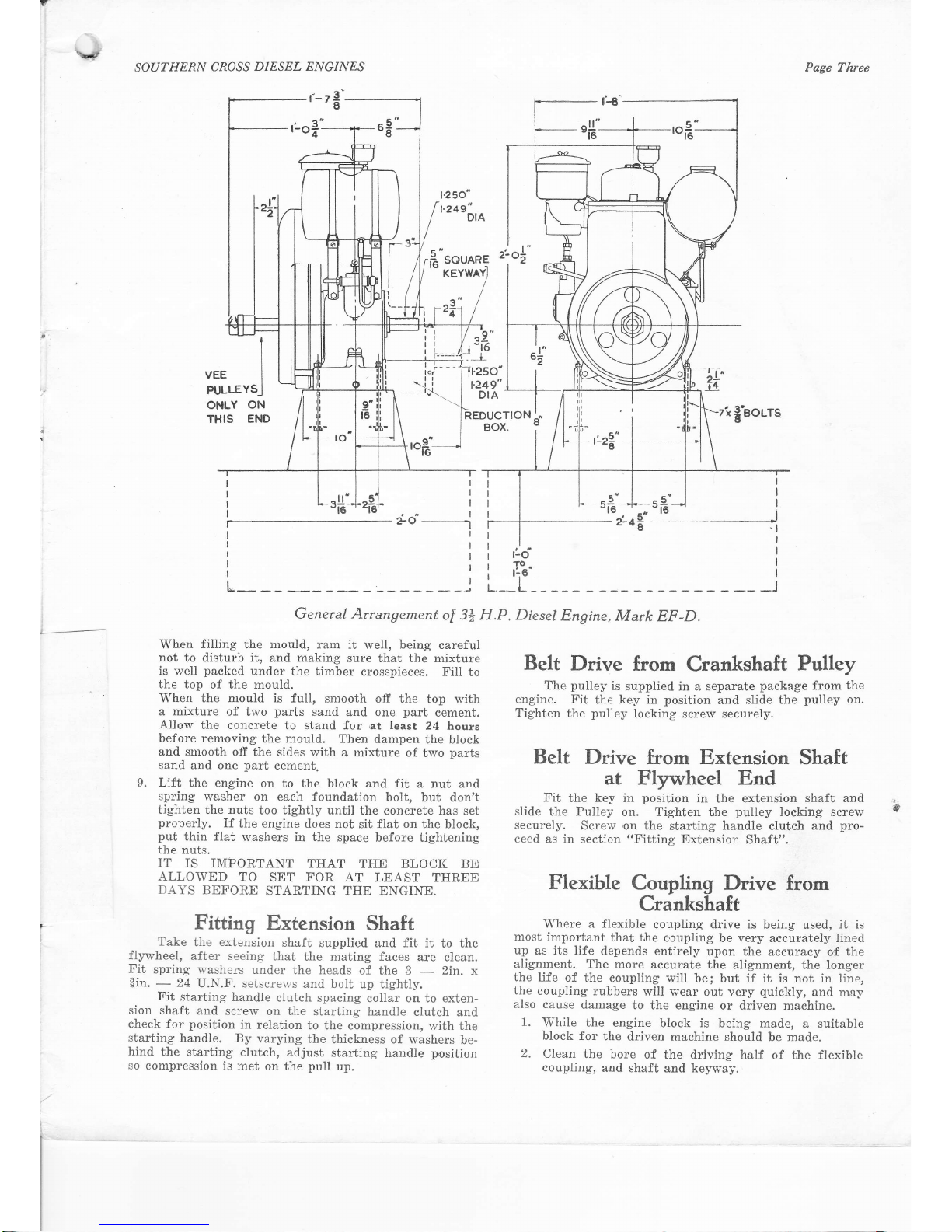
The
Foundation
The engine
should be set up on
a
firm foundation.
The recommended
foundation
is a block
of concrete
as
shown
in
the
illustration,
"Genetal
Arrangement
of 31
h.p.
Diesel Engine,
M'ark
EF-D", on
page
3.
The four
foundation bolts
supplied
with
the
engine should
be set
in
the
concrete block r'vhen
it is
made,
The illustration on
page
3 also
shows the
overall
sizes of the
engine and
the
positions
of
the foundation
bolts.
Engine Drive
Engines
are supplied
for
the
following
types of
dllysg;-
(a)
Belt driving from drive end
,of
Crankshaft
(either
flat or V-Belt
Pulley).
(b)
Belt driving
from
extension shaft
at
flyw,heel end
(V-Belt
Pulley).
(c)
Direct
coupling to
driven machine by
means of a
fiexible coupling.
(d)
Beit
driving from
2
: 1 reduction box
mounted on
engine
(either
flat
or V-Belt
Pulley). Pulley runs
in reverse direction of rotation to engine crankshaft.
(e)
Direct
coupling
by means,of a flexible coupling
from
2 : 1 reduction box mounted on engine.
Flexible coupling runs in
reverse d'irection
of
rota-
tion
to engine cranhshaft.
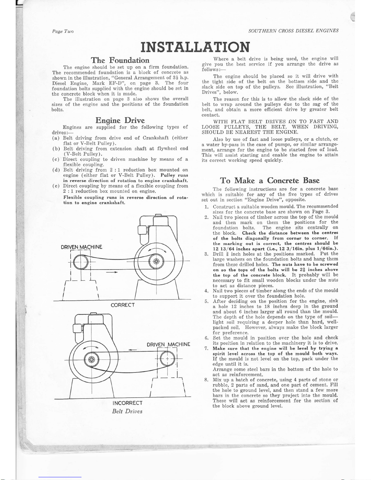
INCORRECT
Belt Dtiues
Where
a
belt drive is being used,
the engine
will
give you
the
best ser-vice if
you
arrange
the
drive
.as
follows:-
The engine should be
placed
so
it will
drive with
the tight
side of the belt on
the bottom
side and
the
slack side on top
,of
ihe
pulleys.
See
illustration,
"Belt
Drives",
belolv.
The reason
for this is to allow the
slack side
of the
belt to
rvrap around
the
pulleys
due to
the sag of
the
beit, and obtain
a more efficient drive
by
greater
belt
contact.
\,VITH
FLAT BELT DRIVES ON
TO
FAST
AND
LOOSE PULLEYS,
THE
BELT,
WHEN
DRIVING,
SHOULD
BE
NEAREST
THE
ENGINE.
Also by
use
of
fast
and
loose
puileys,
or a clutch,
or
a water by-pass in the case of
pumps,
or
similar arrange-
ment, arrange for
the
engine to
be started
free of load.
This will assist starting
and enable the
engine to attain
its correct rvorking speed
quickly.
To
Make a Concrete
Base
The
following instructions
are
for a concrete
base
which
is
suitable
for any of
the five
types of
drives
set
out
in section
"Engine
Drive", opposite.
1.
Construct
a suitable wooden
mould. The
recommended
sizes
for the concrete base
are shown
.on
Page 3.
Nail tu'o
pieces
of
timber across
Lhe top of
the
mould
and
then
mark
on
them the
positions
for the
foundation
bolts. The engine
sits
cenlrally
on
the block. Check
the distance
between
the centres
of the bolts diagonally
from corner
to corn€r.
If
the
maiking out is correct,
the centres
should
be
12
13/64
inches apart
(i.e.,
12 3/16in.
plus
1/64in.).
Drill
I
inch holes at
the
positions
marked.
Put the
large washers on the foundation bolls
and
hang them
from
these drilled
holes. The
nuts have
to be
screwed
on
so
the tops
of the bolts will
be 2E inches
above
the top of the concrete
block.
It
probably
will
be
necessary to fit small rvo'oden
blocks under
the
nuts
to act as
dislance
pieces.
Nail two
pieces
of timber
along
the
ends of
lhe
mould
to
support
it over the foundation
hole.
After
deciding
on the
position
for the
engine,
sink
a
hole 12 inches to 18 inches
deep in
the
ground
and about
6 inches larger all
round
than
the mould.
The depth of the
hole
depends
on the
type of soil-
light soil requiring a deeper
hole than
hard, well-
packed
soil.
Holever,
always
make the block
larger
for
preference.
Set the
mould in
position
over
the
hole and check
its
position
in relation to the
machinery it
is to drive.
Make
sure
that the
engine will
be level by
trying a
spirit level
across
the top
of
the
mould
both ways.
If
the
mould is
not
level on the top,
pack
under
the
edge until it is.
Arrange some steel bars in the
bottom of the
hole
to
act
as
reinforcement.
Mix
up a
batch
of concrete,
using
4
parts
of
stone
or
rubble, 2
parts
of sand, and one
part
of
cement,
Fili
the hole to
ground
level, and
then stand a
few more
bars
in
the concrete so
they
project
into the
mould.
These will act as reinforcement
for the section of
the
block above
ground
level.
DRIVEN
MACHINE
CORRECT
2.
4.
5.
6.
7.
8.
\J
SOATHERN
CROSS
DIESEL ENGINES
Page Three
I
I
VEE I
PULLEYS-l
ONLY
ON
THIS
END
'--78
t.2so"
1 24g"
DIA
t.
l""sounee
KEYWAYI
t249"
DIA
REDUCTION
-"
Box.
6
2.d-----i
L,
General Arrangement
of
jls
H.P. Dieset
Engine,
Mark
EF-D.
r:d
I
rcl
r.t6' I
__L__ ______l
When
filling
the
mould,
ram it weII, being
careful
not to disturb it,
and
making
sure
that the mixture
is weII
packed
under the timber
crosspieces.
Fill to
the top
of the mould.
When the mould
is full, smooth
off the
top with
a mixture
of two
parts
sand
and one
part
cement.
Allow
the concrete
to stand for
.at
least
24 hours
before rem,oving
the mould.
Then
dampen
the block
and
smooth off
the sides with
a mixture of
two
parts
sand
and one
part
cement.
9.
Lift
the engine
on to the block and fit
a nut and
spring
washer
on each foundation
bolt,
but don't
tighten the nuts
too
tightly
until the
concrete has set
properly.
If
the engine
does not
sit flat
on
the block,
put
thin flat
washers
in
the
space
before tightening
the
nuts,
IT
IS IMPORTANT
THAT
THE
BLOCK
BE'
ALLOWED
TO
SET
FOR AT
LEAST THREE
DAYS
BEFORE
STARTING THE ENGINE.
Fitting
Extension
Shaft
Take
the
extension
shaft
supplied and fit it
to the
flywheel,
after
seeing
that
the mating faces
are
clean.
Fit
spring rl'ashers
under
the heads
of
the 3
-
2in. x
3in.
-
24
U.N.F. setscrervs
and bolt
up tightly.
Fit
starting
handle
clutch
spacing
collar on to exten-
sion shaft
and
screw
on the
starting handle
ciutch
and
check
for
position
in
relation
to the
compression,
with the
starting
handle.
By
varying
the
thickness of washers
be-
hind the
starting
clutch, adjust
starting
handle
p,osition
so compression
is met
on the
pull
up.
s9"--L-s9"-J
I
jr.o8"
'"
-!
Belt
Drive
from
Crankshaft
Pulley
The
pulley
is supplied
in a separate
package
from
the
engine.
Fit
the key in
position
and slide
the
pulley
on.
Tighten
the
pulley
locking screw securely.
Belt
Drive
from Extension Shaft
at Flywheel
End
Fit
the
key
in
position
in
the extension
shaft and
slide
the Pulley
on. Tighten
the
pulley
locking screw
securely.
Screw
,on
the
starting
handle
clutch
and
pro-
ceed
as in section
ttFitting
Extension
Shaft".
Flexible
Coupling Drive
from
Crankshaft
Where
a
flexible
coupling drive is being
used,
it
is
most
important
that the
c'oupling
be
very
accurately lined
up as its
life
depends entirely
upon the
accuracy of
the
alignment.
The more
accurate
the alignment, the
longer
the
life of
the coupling
will be;
but
if
it is not in line,
the
eoupling
rubbers
will
wear out very
quickly,
and
rnay
also
cause
damage
to the engine
or driven machine.
1.
While
the engine
block is being made,
a suitable
block for
the
driven
machine should
be made.
2,
Clean
the bore
of
the driving half
of the flexible
coupling,
and
shaft
and
keyway.
i-
'*.-
Page Four
5.
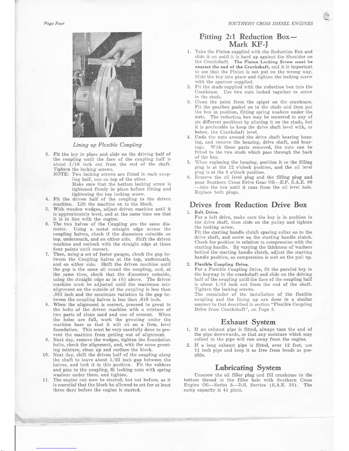
Lining up Flexible Coupling
Fit
the key in
place
and
slide
on the driving
half of
the
coupling until the face of the
coupling
half
is
about
1/16 inch out from the
end of the shaft.
Tighten the locking screws.
NOTE:
Two locking
scre\\,'s
are
fitted in
each
coup-
ling
half,
one on top of the
other.
M,ake sure that
the
bottom
locking
screw is
tightened firmly
in
place
before
fitting and
tightening
the top locking screrv.
Fit
the driven
half
of
the coupling to the
driven
machine. Lift
the
machine
on to the
block.
With
wooden wedges,
adjust driven
machine until it
is approximately level,
and at the
same time see
that
it is in line
with the engine.
The
two halves
of
the
Coupling
are the same dia-
meter.
Using a metal straigJit edge across the
coupling halves,
check
if the
diameters
coincide on
top, underneath,
and on either side. Shift
the
driven
machine
and recheck
with the
straight edge at these
four
points
until correct.
Then,
using a set'of feeler
gauges,
check the
gap
be-
tween the Coupling halves
,at
the
top, underneath,
and on either side.
Shift the
driven machine
until
the
gap
is
the same
.a11
round
the coupling,
and, at
the
.same
time, check that the diameters
coincide,
using
the str,aight edge as
in
(6)
above. The
driven
m.achine must be
adjusted
until
the
maximum mis-
aiignment on
the outside of the
coupling is less
than
.005
inch
and the maximum
variation in the
gap
be-
tween the coupling halves is less t,han
.010
inch.
When the aiignment is correct,
proceed
to
grout
in
the bolts
of
the driven
machine
with a
mixture
of
tw,o
parts
of cle,an sand and one of cement.
When
the holes are full, work
the
grouting
under
the
machine
base so that
it
will sit on a
firm,
level
foundation. This must be very carefully done to
pre-
vent
the
machine from
getting
out of alignment.
Next day,
remove
the
wedges,
tighten the
found,ation
bolts,
check the
alignment, and, with the same
grout-
ing mixture, clean up and surface the block.
Next
day, shift the driven half of the coupling ,al,ong
the
shaft
to
leave abofi
I/32
inch
gap
between
the
halves,
and lock it in this
position.
Fit the rubbers
and
pins
to the coupling,
fit locking
nuts with
spring
washers under them, and tighten.
The
engine
can now be started, but not before,
as it
is essential that
the block be allowed
to set
for
at least
three days
before the engine is started.
8.
SOUTHERN CROSS
DIESEL ENGINES
Eitting 2:l
Reduction
Box-
Mark KF-I
1.
Take
the
Pinion
supplied
*'ith the
Reduction Box and
slide it
,on
until it is hard
up
against
the Shoulder
on
the Crankshaft. The Pinion Locking
Screw
must be
nearest
th,e end
of
the
Crankstraft, and
it is important
to
see that the Pinion
is
not
put
on the
wrong way,
Slide
fhe key into
place
and tighten the
locking screw
rvith
the
spanner
supplied.
2, Fit
the studs supplied
with the reduction box
into
the
Crankcase.
Use two nuts locked together to
screw
in the studs.
3. Clean
the
paint
from the
spigot
,on
the crankcase.
Fit
the
gearbox
gasket
on
to
the studs
,and
then
put
the
box in
position,
fitting
spring washers under
the
nuts.
The reduction
box
may
be
mounted in any of
six different
positions
by altering it on the studs,
but
it is
preferabie
to keep the drive shaft level with,
or
below,
the Crankshaft level.
4.
Undo the nuts ,around
the
drive shaft bearing
hous-
ing, and
remove the housing,
drive
shaft, and
bear-
ings.
With these
parts
removed, the
nuts
c.an
be
fitted
to the two studs which
p,ass
through the back
of the box.
5. lVhen replacing
the housing,
position
it so
the filling
plug
is at
tlne 72 o'clock
position,
and
the oil
level
plug
is at
the
8
o'ci,ock
position.
6. Remove
the oii level
plug
and
the
filling
plug
and
pour
Southern Cross Drive Gear Oil-E.P. S.A.E.
90
-into
the box until
it
runs
from the
oil
level hole.
Replace
both
plugs,
Drives from
Reduction
Drive Box
1.
Belt Drive.
For
a belt drive, make
sure the
key is in
position
in
the drive shaf't,
then slide on
the
pulley
and
tighten
the locking screw.
Fit
the starling handle
clutch
spacing collar on to the
drive
shaft, and screw on the starting
handle clutch.
Check for
position
in relation to
compression
with the
starting
,handle. By
varying the thickness
of washers
behind the starting handle
clutch,
adjust the starting
handie
position,
so compression
is met on the
puli
up.
2. Flexible Co,upling
Drive.
For ,a
Flexible
Coupling
Drive, fit
the
parallel
key in
the
keyu'ay
in
the crankshaft and slide
,on
the
driving
half
of the coupling
until
the f,ace
of
the coupling
half
is about 1/16
inch out from the end of the shaft,
Tighten
the
locking
screws.
The remainder
of the installation of the
flexible
coupiing and
the lining up
,are
done
in a
similar
manner
to that described in section
"Flexible
Coupling
Drive
frorn Crankshaft",
on
P,age
3.
Exhaust
System
1.
If
an exhaust
pipe
is fitted, always turn the end of
the
pipe
downv'ards,
so that any
moisture which may
collect
in
the
pipe
will run away from the engine.
2, If.
a long exhaust
pipe
is fitted,
over
12 feet, use
11 inch
pipe
and
keep it as free
from
bends as
pos-
sible.
Lubricating System
Unscrew the
oil
filler
plug
and fill crankcase to
the
bottom
thread in the filler
hole
with
Southern Cross
Engine Oil-Series
3-D.S. Service
(S.A.E.
20).
The
sump
capacity is
4i
pints.
4.
6.
7.
o
10.
11,
SOL]THERN
CROSS
DIESEL
ENGINES
Fitting
Oil
Bath
Air
Cleaner
The Oil
gith
Ai" Cleaner
Assembly
is
to
be
fitted to
the
engine before
starting.
To do
this,
fit
the
Oil Bath
Air Clianer
Adaptor
to
the
studs
in the
Cylinder
Head,
and tighten
the
nuts.
IJnscrew
the
Wing
Nut
and remove
the Cover.
FiIl
Oil
B,ath
up
to the
oil
leve1
mark
with
clean
engine
oil
and
refit
the
element
and
cover.
Fuel
SYstem
FilI the
fuel
tank with
fuel
which
is clean
and
free
from
water.
(See
page
?
for
"Fuel
Recommendations"')
If in doubt
about
cleanliness
of
fuel,
strain
it
through
a
fine
gauze
strainer
before
filling into
tank'
18 Gallon
Fuel
Tank
(Supplied
as
o.
1.
an
Extra)
Disconnect
the
fuel tank
to
filter
tube
and
injector
,overflow
tube
and
remove'
taking
care
not to
lose
the
washers
from either
side
of
the banjos.
Remove
fuel
tank
,and
fuel
tank
brackets
from the
engine.
R,emove
banjo
and
collar
from
the
injector
overflow
tube by
holding
them
in
boiling
water
for
about
4
minute
and
then
withdr,awing
and
removing
them.
The
banjo
and collar
,are
to
be
fitted to
the end
of
the
longer
injector
overflow
tube,
supplied
with
the
Preparing
the
Engine
For
Running
T5 start
the
engine
for the
first time,
or after
an
overhaul,
or any
operation
during
whioh the
lubricating
oil
has been
drained
fr"om
the sump'
or
after the
fuel
tank
has been
ailowed
to
run dry,
the
following
instruc-
tions must
be carried
out
in the
order
given,
other^wise
the
engine
may not
statt, ot,
if it does,
it may
be dam,aged'
Check
the following
(see
Pages
4 and
5) :-
1. Fuel
in fuel tank.
2.
OiI
levei in
Engine Sump.
3. Oil
in Oil
Bath Air Cleaner.
Retarding
Iniection
Timing
(.Export
Engines
OnlY)
Diesel
fuels
obtainable
outside
Australia
vary con-
siderably.
To
assist
in starting
the
engine
the
injection
timing
may be
retarded
up to
5o
from
the factory
setting.
Degree
rnarkings
on the
flywheei
alongside
the
"Pump"
mark are
provided to assist
in this
'adjustment.
At the
factory,
the
injection timing
is set so that
the
fuel ceases
to
flow
when the
"pump"
mark
on the
flywheel
is opposite
the
mark
on the
fuel
pump
mounting
plate.
(See
illustration,
"Checking
Fuel Pump
Timing",
on
Page
Twelve.
)
To retard
the
injection
timing, adjust
the
fuel
pump
r"ocker
adjusting
screw.
Read
Section
(5),
"Check
Fuel
Pump Timing",
on
Page
Twelve.
Under
no circumstances
is the
fuel
pump
timing
to
be
retarded
beyond
the 5o
marking.
Priming
Fuel
System
IMPORTANT-If
you don't
follow
these
instructions
the engine
won't
start, as
the
fuel
system
must be abso-
lutely full
of
fuel and
free from
air.
1. Shift
fuel stop
cock
to
"on"
position
by
gripping
the
knurled
sleeve
and
sliding
it downwards
as
far
as
it will
go.
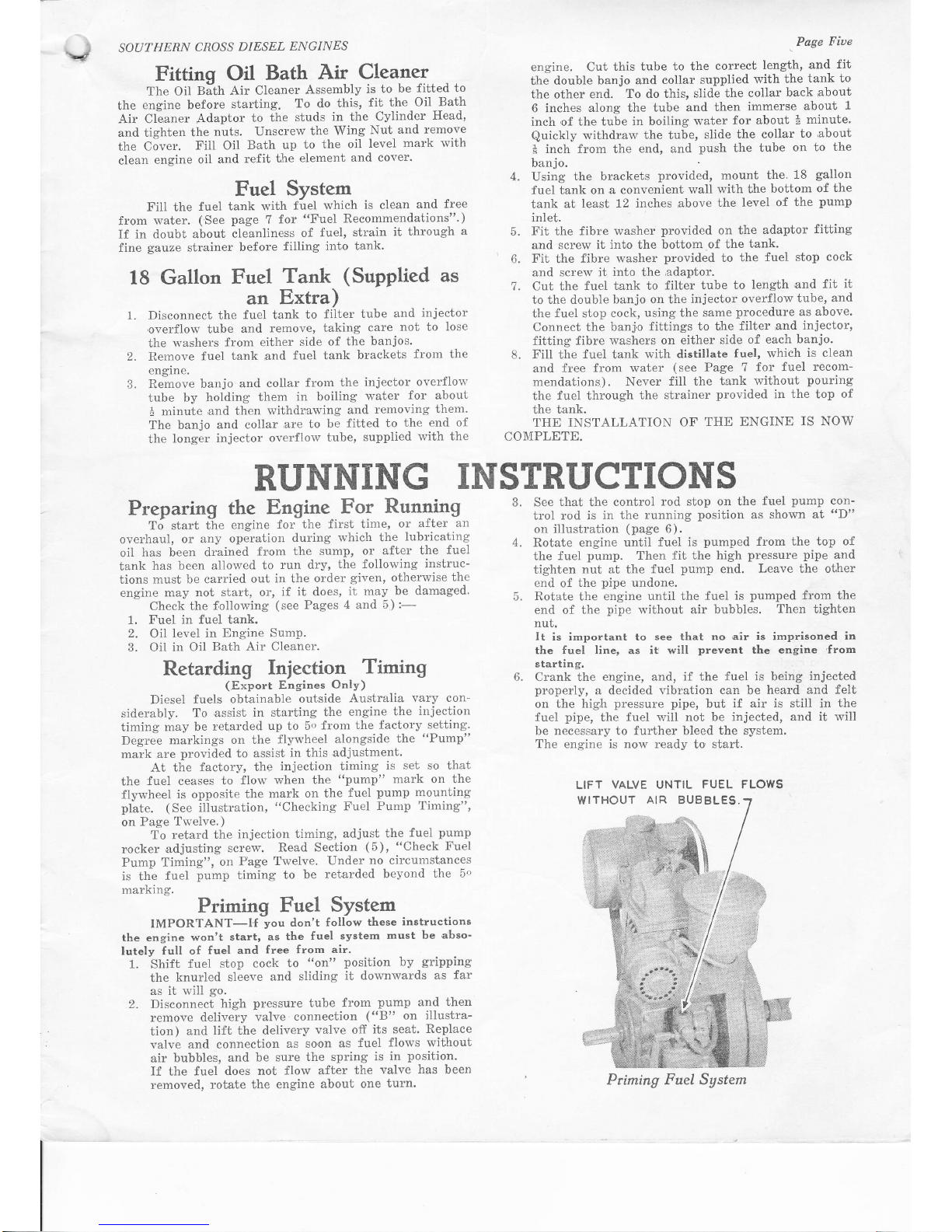
2. Disconnect
high
pressure tube from
pump
and
then
rernove delivery
valve
connection
("8"
on illustra-
tion)
and lift
the delivery
valve off
its seat.
Replace
valve and
connection
as so'on
as
fuel
flows without
air
bubbles,
and
be sure the
spring
is
in
position.
If
the
fuel
does not
flovr after
the
valve
has
been
removed,
rotate the
engine
about one
turn'
4.
,Page
Fiue
engine. Cut this
tube
to the
correct
length,
and
fit
the
double
banjo and
collar
supplied
with
the
tank to
the other
end.
To
do
this,
slide the
collar
back
about
6 inches
along the tube
and
then
immerse
about
1
inch
,of
the tube in
boiiing water
for
about
*
minute.
Quickly
withdraw
the
tube,
slide
the collar
to
,about
*
inch from the
end, and
push
the tube
on to
the
banjo.
Using
the brackets
provided,
mount the.
18
gallon
fuel
tank on.a
convenient
wall
with the
bottom
of
the
tank
at le.ast
12 inches
,above
the level
of the
pump
inlet.
Fit
the
fibre washer
provided
on
the
adaptor
fitting
and
screw it
into
the
bottom
of the
tank.
Fit
the
fibre
washer
provided
to
the
fuel stop
cock
and screw it
into
the
adaptor,
7.
Cut the
fuel
tank to
filter tube
to length
and fit
it
to the double
banjo on the
injector
overflow
tube,
and
the fuel stop
cock,
using
the
same
procedure
as
above'
Connect the
banj,o
fittings
to the filter and
injector,
fitting
fibre washers
on either
side
of each
banjo.
8. FilI the
fuel
tank
with
distillate
fuel,
which
is clean
and free from
water
(see
Page 7
for fuel
recom-
mendations,).
Never
fill the
t'ank without
pouring
the
fuel through
the strainer
provided
in
the
top
of
the
tank.
THE INSTALLATION
OF
THE
ENGINE
IS NOW
COMPLETE.
See
that
the
contro]
rod stop on the
fuel
pump
con-
trol rod is
in the
running
position
as
shown
at
"D"
on
iilustration
(page
6).
Rotate engine until
fuel
is
pumped
from the
top of
the fuel
pump.
Then fit
the high
pressure
pipe
and
tighten
nut at the
fuel
pump
end.
Leave the oiher
end of
the
pipe
undone.
Rotate the engine
until the
fuei is
pumped
from the
end of
the
pipe
wrlthout
air bubbles.
Then tighten
nut.
It is important to
see that no air
is
imprisoned
in
the fuel line, as
it
will
prevent
the engine
'from
starting.
Crank the
engine, and,
if the fuel is being
injected
pr'operly,
a decided vibration can be
heard and
felt
on
the high
pressure pipe,
but
if
air
is still
in
the
fuel
pipe,
the fuel
vrill not be injected,
and it
will
be necessary to further bleed the system.
The engine is now ready
to,start.
5.
6.
2.
RUNNING
INSTRUCTIONS
o.
4.
5.
6.
LIFT
VALVE
WITHOUT
UNTIL
FUEL FLOWS
AIR
BUBBLES.
Priming
Fuel Sgstem
I
SOUTHERN
CROSS
DIESEL
ENGINES
Page Sir.
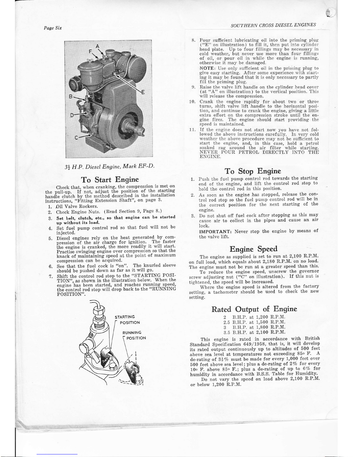
3+
H,P.
Diesel
Engine,
Mark
EF-D'
To
Start
Engine
C,heck
that,
when
cranking,
the
compression
is
met on
tfte
putLup.
If
not, adjust
t'iie
position
of
the
starting
rri"ai"-.ti,,iih
bv
the
me[hod
desciibed
in
the
installation
instrrrctions,
"Fitting
Extension
Shaft",
'on
page
3'
1. Oil
Valve
Rockers.
2. Check
Engine
Nuts.
(Read
Section
9,
Page
8')
3.
Set
belt,
clutch,
etc.,
oo that
engine
can
bc
started
up
without
its
load.
4. Set
fuel
pump
control
rod
so
that
fuel
will not
be
8. Pour sufficient
lubricating
oil
into
the
priming plug
("E"
on iilustration) to fill
it,
then
put
into cylindei'
head
plate.
Up to
four fillings may
be
necessary
in
cold
weather, but
never
use
more
than
four fillings
of oil, or
pour
oil
in while
the
engine
is running,
otheru'ise it may
be
damaged.
NOTE:
Use only
sufficient
oil
in the
priming plug
to
gil'e
easy starting. After
some
experience r.r'ith st.art-
ing it may be found that it is only
necessary
to
partll'
fill
the
priming plug.
Raise
the
val'r'e lift handle
on
the cylinder
head
cover
(at
"A"
on
illustr.ation)
to the vertical
position.
This
q'iil
release
the
compression.
Crank the
engine
rapidly for about
two
or three
turns, shift
valve lift
handle
to
the horizontal
posi-
tion, and
continue to crank
the
engine,
giving
a little
extra
efrort on the c'ompression stroke until the en-
gine
fires. The engine
should start
providing
the
speed
is
maintained.
If
the
engine
does not start norv
you
have not fol-
Iowed
the
above instructions
calefully, In very cold
weather
the above
procedure
may not be sufficient
to
start the engine,
and, in this
case,
hold
a
petrol
s'oaked
rag around the
air filter tvhile starting.
NEVER POUR
PETROL
DIRECTLY INTO THg
ENGINE.
o
10.
11.
injected.
Diesel
engines
rely
on
the
heat
generated-by
com-
"ression
if
ttre
aii
charge
for ignition'
The
faster
ltte eneine
is cranked,
the
more
readily
it will start'
Fiu.ilff
swinging
engine
over
c'ompression-so
that the
knack
of
maiitaining
speed
at the
point
of
maximum
compression
can
be
acquired.
See that
the
fuel cock
is
t'on".
The
knurled
sleeve
should
be
pushed
down
as
far
as it
will
go.
Shift
the
control
rod stop
to the
"STARTING
POSI-
iiOit'1, as
shown
in the
illustration
below.
.When
the
e Eine'has
been
started,
and reaches
running
speed,
th6
contnol
rod stop
wilt drop
back to the
"RUNNING
POSITION'"
1.
To Stop
Engine
Push the
fuel
pump
control
rod towards
the
starting
end of
the
engine,
and
lift the
control
rod
stop
to
hold the
control
rod
in this
position.
As soon
as
the engine
has stopped,
release
the
con-
trol
rod stop
so the
fuel
pump
control
rod
will
be
in
the correcC
position
for
the
next starting
of
the
engine,
Do
not shut
off fuel
cock
after
stopping
as
this
may
cause air
to collect
in
the
pipes
and
cause
an
air
lock.
IMPORTANT:
Never
stop
the
engine
by
means
of
the
valve
lift.
Engine
Speed
The engine
as supplied
is set to
run
at
2,100
R'P'M'
on full
load, which
equils
about
2,180
R.P.M'
on
no load'
The engine
must
not be
run at
a
greater
speed
Lhan
this'
To
reduce the
engine
speed,
unscrew
the
governor
screw
adjusting
nut
("C"
on
illustr,ation).
If this
nut
is
tightened,
the
speed
will be
increased'
Where
the
engine
speed
is altered
from
the
factory
setting,
a tachometer
should
be
used
to check
the
new
setting.
Rated Output
of
Engine
2 B.H.P.
at I,200
R.P.M'
2.5 B.H.P.
at
1,500
R.P.M.
3
B.H.P. at
1,800
R.P.M.
3.5
B.H.P. at
2,700
R.P.M'
This engine
is rated
in
accordance
with
British
Standard
Specification
649/L958,
that
is,
it
will develop
its rated
oulput
oontinuously
up
to
altitudes
of 500
feet
above
sea
level at
temperatures
not
exceeding
85o
F.
A
de-rating
of 3t%
must
be
made
for
every
1,000
feet over
500
feet above
sea
level;
plus
a
de-rating
of2/o
for every
10o
F. above
85o
F.;
plus
a
de-rating
of
up
to 6Vo
fot
humidity
in accordance
with
B.S.S.
Table
for
Humidity'
Do not vary the
speed
on
load
above
2'100
R'P.M'
or
below
1,200
R.P.M.
,
t.
5.
6.
7.
STARTING
POSITIoN
RUNNING
 Loading...