

Page 1
Ed : 03/17 Rev : 00
INSTRUCTION
Page 2
2
The treadmill has been designed and constructed to provide trouble free usage and enjoyable exercise.
You can greatly improve your understanding and benefits of exercising by carefully reading the instructions
given in this manual. Please familiarize yourself with the maintenance advice provided for you.
• Drive Motor: 1.2 HP
• Speed Range: 1.0 –12kmph
• Running Surface: 420 m/m x 1200 m/m
• Folding Design: Yes
MAX.USER WEIGHT 100 KGS
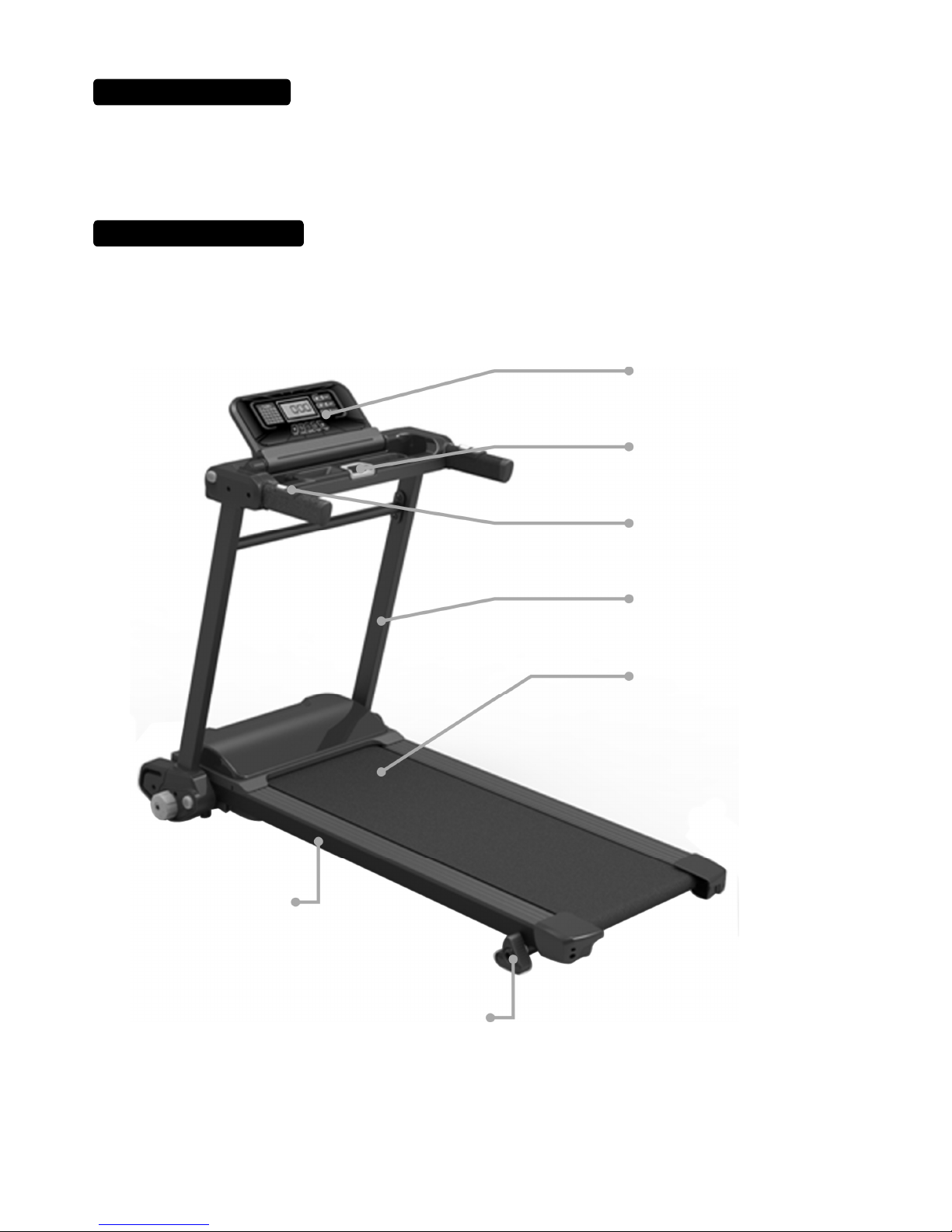
SPECIFICATIONS
Handrail
Running Belt
Main Frame
Safety Key
Console
Inclination Adjustor
Handpulse
Page 3
3
ASSEMBLY
PACK
CHECK
LIST
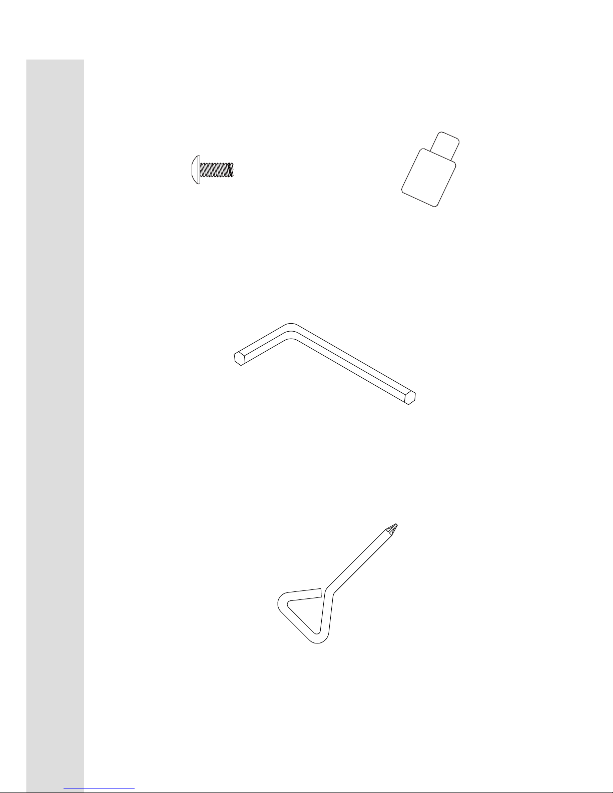
ASSEMBLY PACK CHECK LIST
#99. M5 × P0.8 × 12L
Phillips Head Screw (2 pcs)
#111. Lubricant (1 pc)
#112. L Allen Wrench (1pc)
#115. Short Phillips Head Screw Driver (1pc)
Page 4
4
ASSEMBLY
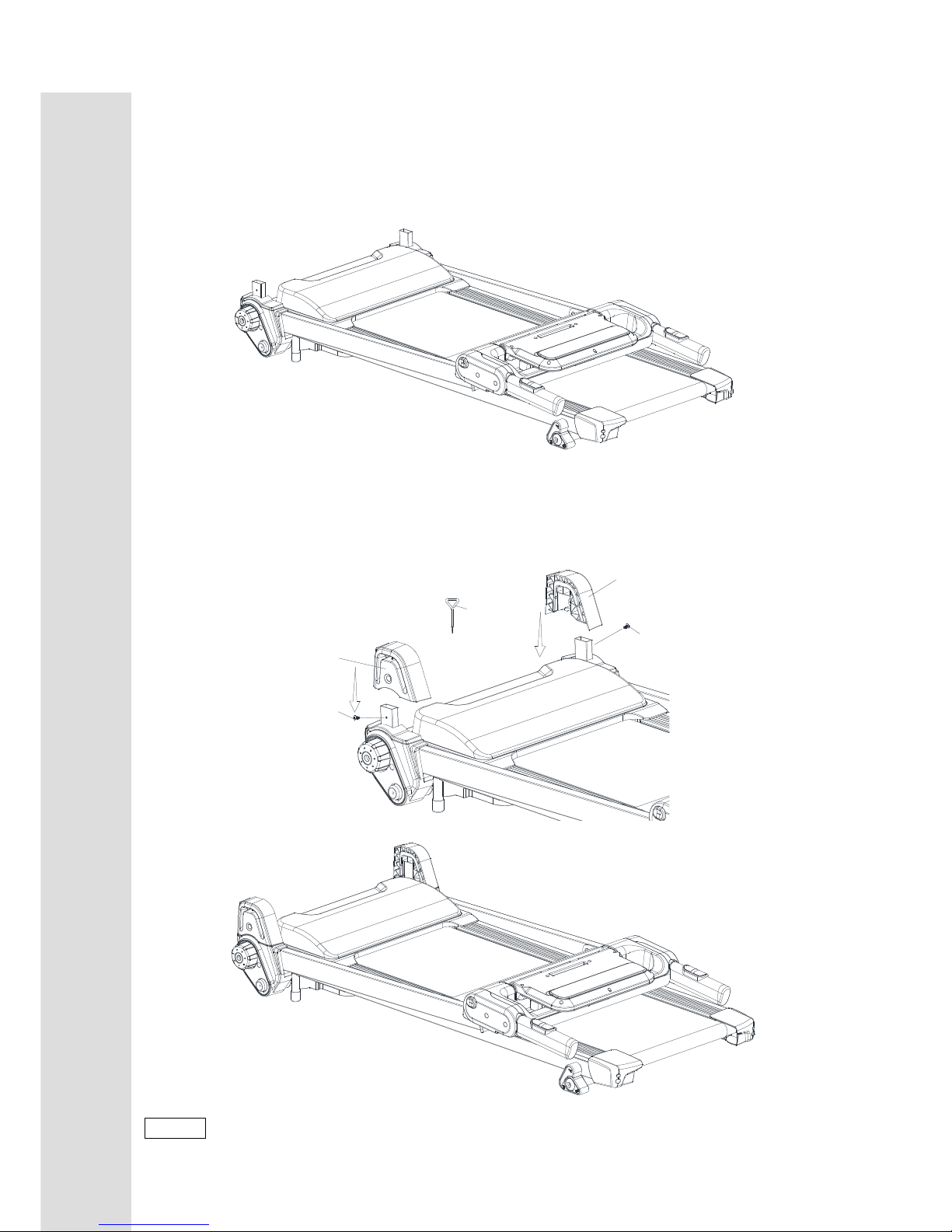
Step 1.
Place the treadmill on level ground.
Step2.
Install Front Frame Base Cover (L)(R) (37) and (38) on the treadmill and use Short Phillips Head
Screw Driver (115) to tighten 2 pcs of M5 × P0.8 × 12L_Phillips Head Screw.
99
99
37
38
115
NOTE: Please Tighten All Screw After All Components Assembly Complete.
ASSEMBLY
Page 5
5
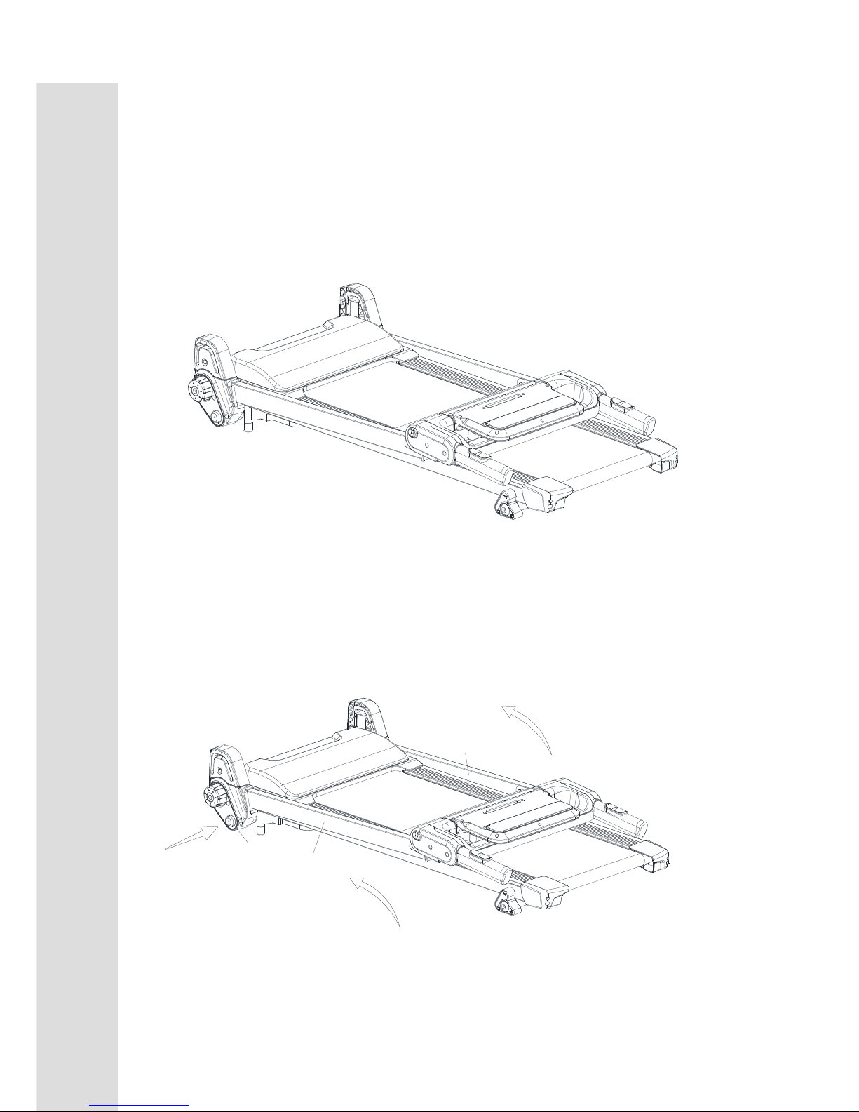
Unfolding Procedure
Step 1.
Place the treadmill on level ground.
Step 2.
Press and hold the Release To Push A Button (Bottom)(48) and pull Uprights (L, R) (3,2) as the
arrow indicates to the end position.
48
3
2
UNFOLDING
FOLDING
TRANSPORT
Page 6

6
Step 3.
Press and hold Release To Push A Button (Top) (23) and turn Console Support (4) as indicated
below and unfold console Assembly (26) into place.
4
23
26
UNFOLDING
FOLDING
TRANSPORT
Page 7
7
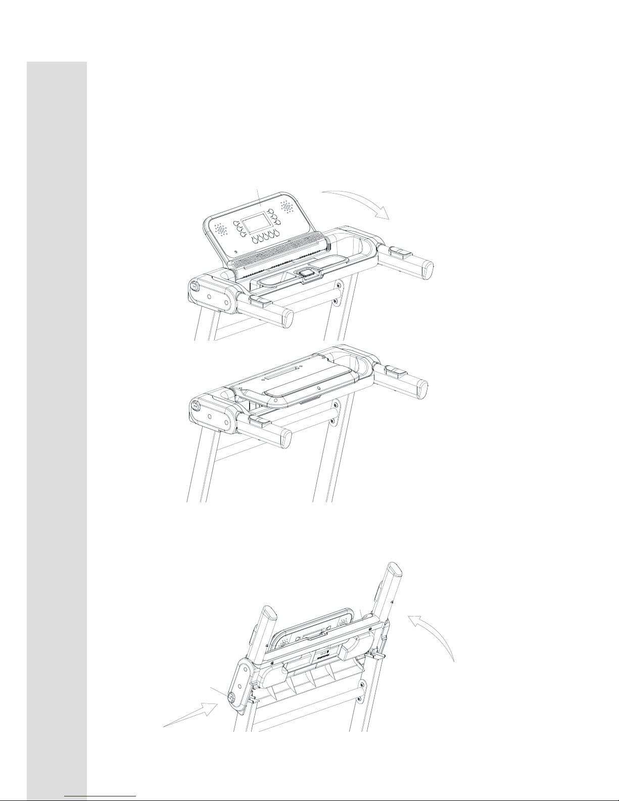
Folding Procedure
Step 1.
Fold Console Assembly (26).
26
Step 2.
Press and hold the Release To Push A Button (Top) (23) and pull Console Support (4) up to the
end.
4
23
UNFOLDING
FOLDING
TRANSPORT
Page 8
8
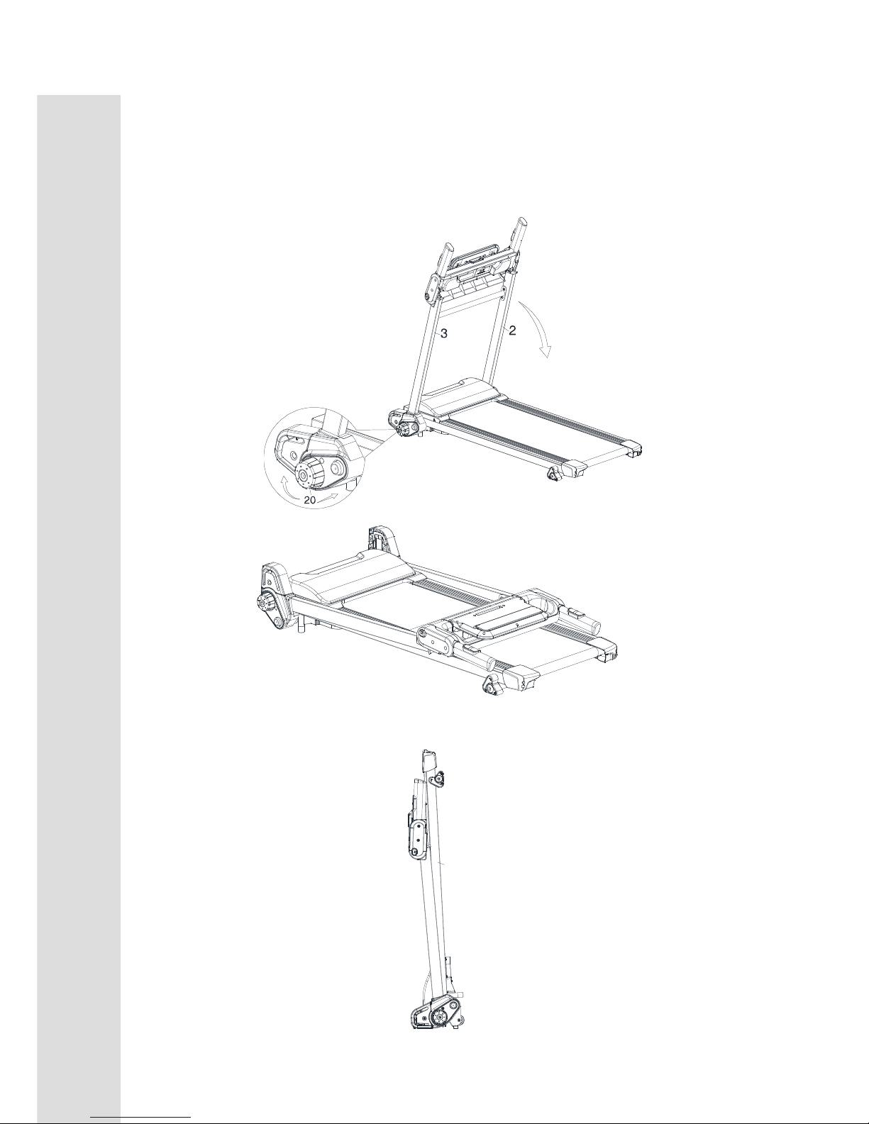
Step 3.
Press and turn Brake Tension Knob (20) clockwise and pull Uprights (L, R) (3,2) as the arrow
indicates to the end position.
Step 4.
Pull up the Main Frame (1) to fold up the treadmill.
1
UNFOLDING
FOLDING
TRANSPORT
Page 9
9
FUNCTIONS
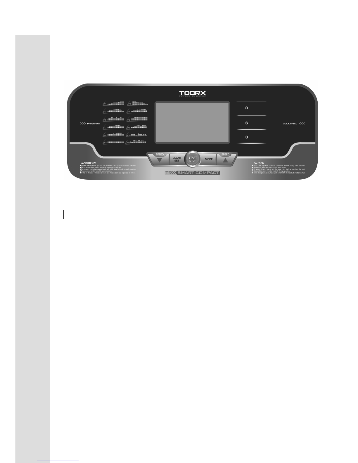
COMPUTER OPERATION INSTRUCTIONS
Button Function
A > “START/ STOP” Button
Press this button to start the operation of the treadmill with the starting speed at 1.0 KPH.
Press it again to stop the treadmill with the speed gradually slow down until full stop.
B > “CLEAR/SET” Button
Pressing this button resets TIME, DISTANCE, CALORIE .When in the manual mode, press this
b
utton to set parameters TIME, DISTANCE, CALORIE . Although three parameters can be set,
only the last parameter set is accepted . press mode key will reset and go to idle mode.
D > “MODE” Button
In ready mode, Press "MODE" button to select the training mode. There are 12 built-in programs
to select.
E > “FAST” Button
1. Press the "FAST" button to increase the speed until the proper speed. Hold this key for 3
seconds will quickly increase the speed.
2. In setting mode, pressing "FAST" button changes the parameter (increases).
F> “SLOW” Button
1. Press the "SLOW" button to decrease the speed until the proper speed. Hold this key for 3
seconds will quickly decrease the speed.
2. In setting mode,pressing "SLOW" button to change the parameter(decreases).
G> “RAPID SPEED” Button
Press quick buttons 3, 6 and 9(KPH) or WALK for low speed, JOG for medium speed and RUN
for high speed,
Page 10

10
FUNCTIONS
Get prepared before using the treadmill
Be sure that the power complies with product specification prior to turning on the treadmill. The red
light of the switch comes on and the console shows E0 when the treadmill turns on. Put the safety
key in place and clip on the other end to the cloth and be ready for the workout.
Quick Start
1.Place the safety key and the treadmill is in manual mode. Press START/STOP button to begin the
workout.
2.The initial speed is 1.0KPH. You can adjust the speed by pressing “FAST”, “SLOW” and “RAPID
SPEED” buttons.
3.You can press START/STOP button or pull out the safety key, in case of emergency, any time when
the treadmill is operating. The speed will slow down gradually till fully stop.
4.While in manual mode, pressing “CLEAR/SET” button sets time, distance and calorie. Pressing
FAST and SLOW buttons changes the value. When finish setting, press START/STOP to begin the
workout. (The system accepts only the last item set. When the value of the set item is reached, the
treadmill stops.)
Handgrip pulse feature
Any time when the treadmill is operating, grasping handgrip shows treadmill pulse feature
and the heart beat value is displayed. Grasp firmly while using this feature otherwise the
value fluctuates.
Calorie Display
The calorie display shows the value of heat energy consumed during the workout.
Built-in programs
Pressing MODE and there are 12 build-in programs, P1, P2, P3 … and P12, to choose. The speed
varies automatically and hence these programs are not recommended for the beginners or children.
Page 11
11
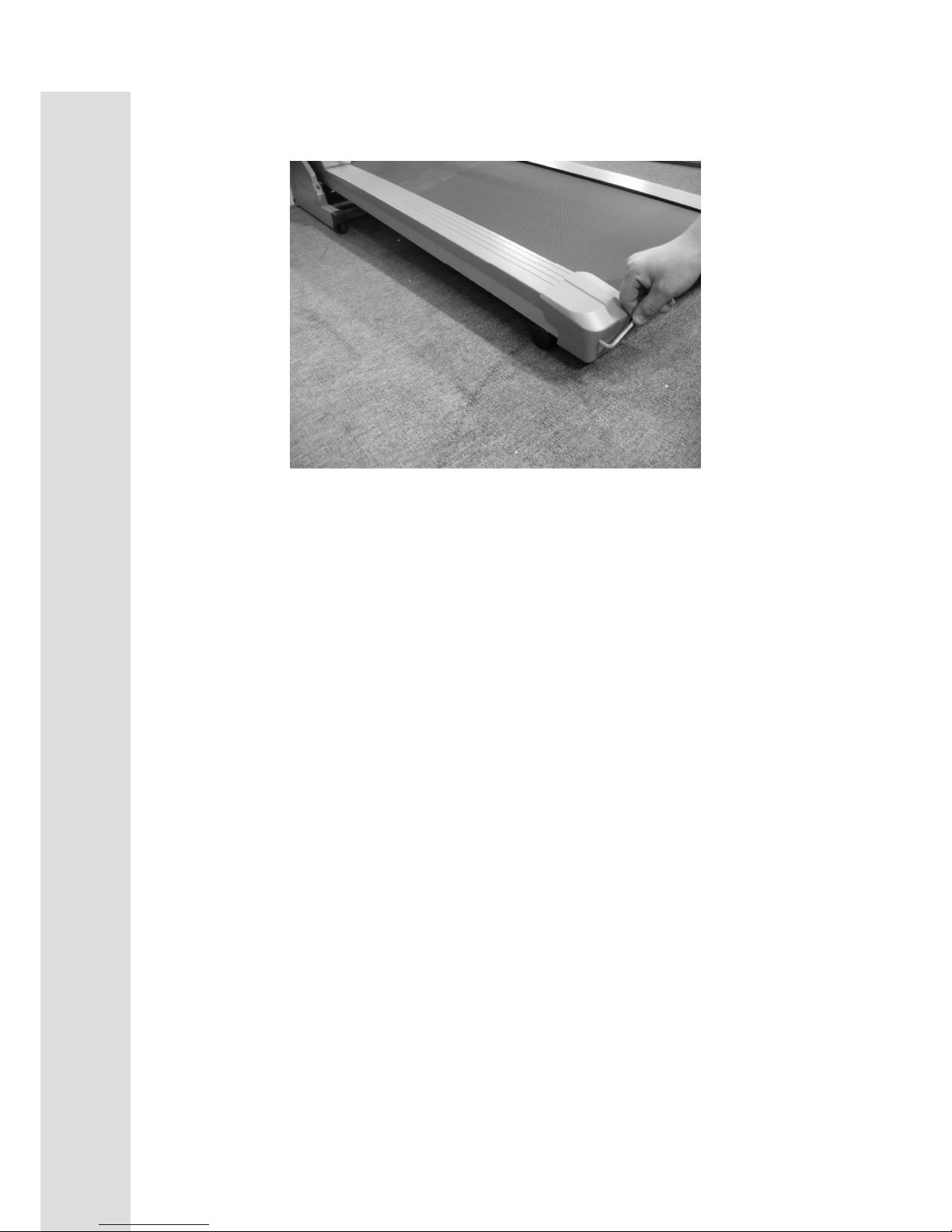
BELT TRACKING ADJUSTMEANT
If during use you notice that walking belt either shifts to the right or the left of center,
first remove "Safety Key" and unplug equipment from AC power source. Using M5
Allen wrench provided, turn left rear roller adjustment as indicated below clockwise no
more the 1/4" of a turn. Remove M5 Allen wrench, insert "Safety Key" and insert AC
power cord into AC outlet. Turn on your treadmill and observe after running a few
minutes to see if problem has been corrected. This may take several adjustments, so
repeat the above procedure.
Page 12
12
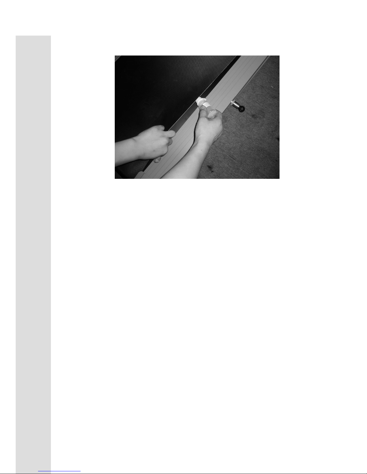
Your treadmill should require little maintenance other then periodically applying lubricant.
Lubricating under the treadbelt will ensure superior performance and extend its life expectancy.
HOW TO CHECK TREADBELT FOR PROPER LUBRICATION?
Lift one side of the treadbelt and feel the top surface of the treadboard.
If the surface is slick to the touch, then no further lubrication is required.
If the surface is dry to the touch, apply one packet of lubricant or half of the bottle of lubricant.
HOW TO APPLY LUBRICANT?
1. Lift one side of treadbelt.
2. Pour one half of the lubricant bottle under the center of the treadbelt on the top surface of the
treadboard.
3. Walk on the treadmill at a slow speed for 3 to 5 minutes to evenly distribute lubricant.
NOTE: DO NOT over lubricate treadboard. Any excess lubricant that comes out should be wiped
off.
IMPORTANT: ONLY USE HALF THE BOTTLE OF LUBRICANT PER APPLICATION
LUBRICATION SCHEDULE.
1. If it’s necessary, it’s better to lubricate half a bottle when user open carton to use at first time.
2. We suggest if user doesn’t apply lubricant at first time, after the first 25 hours of use
(2-3 months ) need to apply one half bottle of lubricant.
3. Every 100 hours or 300 km of use apply one half bottle of lubricant per exact situation.
TREADMILL LUBRICATION
Page 13
15
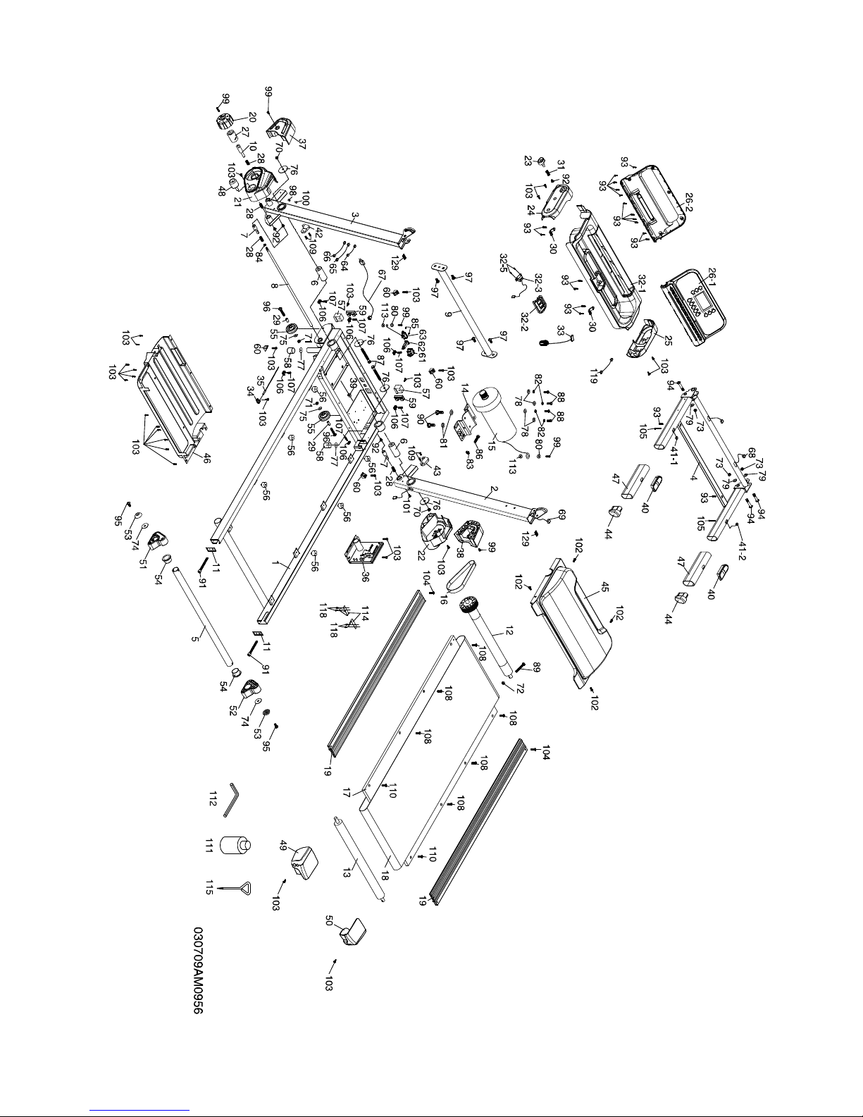
OVERVIEW
Page 14

16
PARTS
LIST
NO. DESCRIPTION Q'TY
1
Main Frame 1
2
Right Upright 1
3
Left Upright 1
4
Console Support 1
5
Inclination Adjustor Bushing Assembly 1
6
Upright Support Axle 2
7
Sprung Latch 2
8
Releasing Bracket Axle 1
9
Handrail Support 1
10
Brake Tension Knob Axle 1
11
Rear Roller Cover 2
12
Front Roller W/Pulley 1
13
Rear Roller 1
14
Motor Bracket 1
15
Motor
1
16
Drive Belt 1
17
Running Deck 1
18
Running Belt 1
19
Foot Rail 2
20
Brake Tension Knob 1
21
Rear Frame Base Cover (L) 1
22
Rear Frame Base Cover (R) 1
23
Release To Push A Button (Top) 1
24
Handgrip Side Cap(L) 1
25
Handgrip Side Cap(R) 1
26
Console Assembly 1
26~1
Console Top Cover 1
26~2
Console Bottom Cover 1
27
Knob Bushing 1
28
Constrict Spring 4
29
Wheel Sleeve 2
30
Beverage Holder Anchor 2
31
Release Spring 1
32~1
Beverage Holder 1
32~2
Safety Key Cover 1
32~3
Safety Switch Module W/ Cable 1
32~5
Ø3 × 10L_Sheet Metal Screw 2
33
Square Safety Key 1
34
Sensor Rack 1
35
1000m/m_Sensor W/Cable 1
36
Motor Controller 1
37
Front Frame Base Cover (L) 1
38
Front Frame Base Cover (R) 1
39
Bushing 1
40
Handpulse Sensor (w/o wire)
2
41~1
1000m/m_Handpulse Wire 1
41~2
700m/m_Handpulse Wire 1
41
1000m/m_Handpulse Wire 2
Page 15

17
PARTS
LIST
NO. DESCRIPTION Q'TY
42
Deck stopper (L) 1
43
Deck stopper (R) 1
44
Handgrip End Cap 2
45
Motor Top Cover 1
46
Frame Cover 1
47
Handgrip Foam 2
48
Release To Push A Button (Bottom) 1
49
Rear Adjustment Base (L) 1
50
Rear Adjustment Base (R) 1
51
Inclination Adjustor (L) 1
52
Inclination Adjustor (R) 1
53
Bolt Cap 2
54
Inclination Adjustor Bushing 2
55
Transportation Wheel 2
56
Rubber Foot 6
57
Foot Pad 2
58
Outer End Cap 2
59
25 × 50m/m_Square End Cap 2
60
Motor Cover Anchor 4
61
On/Off Switch 1
62
Breaker 1
63
Power Socket 1
64
100m/m_Connecting Wire (Black) 1
65
250m/m_Connecting Wire (White) 1
66
250m/m_Connecting Wire (Black) 1
67
Power Cord 1
68
600m/m_Computer Cable(Upper) 1
69
950m/m_Computer Cable(Lower) 1
70
3/8" × UNC16 × 7.0T_Nyloc Nut 2
71
5/16" × UNC18 × 7.0T_Nyloc Nut 2
72
M8 × P1.25 × 7.0T_Nyloc Nut 1
73
M10 × P1.5 × 8T_Nyloc Nut 3
74
Ø8 × Ø35 × 1.5T_Flat Washer 2
75
Ø8 × Ø16 × 1.5T_Flat Washer 2
76
Ø10 × Ø35 × 2.0T_Flat Washer 4
77
Ø8.5 × Ø25.4 × 1.5T_Flat Washer 2
78
Ø10 × Ø25 × 2.0T_Flat Washer 4
79
Ø19 × Ø10 × 1.5T_Flat Washer 3
80
Ø5 × 1.5T_Split Washer 2
81
Ø8 × 1.5T_Split Washer 2
82
Ø10 × 2T_Split Washer 4
83
3/8" × UNC16 × 7T_Nut 1
84
M6 × P1.0 × 5.0T_Nut 1
85
Ø3 × 10L_Sheet Metal Screw 2
86
3/8" × UNC16 ×1-1/4"_Hex Head Bolt 1
87
3/8" × UNC16 × 3-1/2"_Hex Head Bolt 2
88
3/8" × UNC16 × 3/4"_Hex Head Bolt 4
89
M8 × P1.25 × 60L_Hex Head Bolt 1
Page 16

18
PARTS
LIST
NO. DESCRIPTION Q'TY
90
M8 × P1.25 × 12L_Hex Head Bolt 2
91
1/4" × UNC20 × 60L_Socket Head Cap Bolt 2
92
M5 × P0.8 × 10L_Flat Phillips Head Screw 4
93
Ø3.5 × 12L_Sheet Metal Screw 19
94
M10 × P1.5 × 50L_Button Head Socket Bolt 3
95
5/16" × UNC18 × 1"_Button Head Socket Bolt 2
96
5/16" × UNC18 × 42L_Button Head Socket Bolt 2
97
5/16" × UNC18 × 3/4"_Button Head Socket Bolt 4
98
Fastening Bushing 1
99
M5 × P0.8 × 12L_Phillips Head Screw 5
100
M4 × P0.7 × 12L_Phillips Head Screw 1
101
M6 × P1.0 × 15L_Phillips Head Screw 1
102
Ø5 × 16L_Tapping Screw 4
103
Ø5 × 16L_Tapping Screw 28
104
Ø5 × 25L_Tapping Screw 2
105
Ø4 × 56L_Sheet Metal Screw 2
106
Wire Tie Mount 6
107
Ø3.5 × 16L_Tapping Screw 6
108
M6 × P1.0 × 20L_Flat Head Socket Screw 6
109
M5 × P0.8 × 15L_Flat Head Socket Screw 4
110
M6 × P1.0 × 25L_Flat Head Socket Screw 2
111
Lubricant 1
112
L Allen Wrench 1
113
M5_Star Washer 2
114
Belt Guide 2
115
Short Phillips Head Screw Driver 1
116
Ø5 × 19L_Tapping Screw 1
118
Ø4 × 12L_Sheet Metal Screw 4
119
1
200m/m_Safety Switch Wire 1
129
Rubber Pad 2
Page 17

GARLANDO SPA
Via Regione Piemonte, 32 - Zona Industriale D1
15068 - Pozzolo Formigaro (AL) - Italy
www.toorx.it - [email protected]
 Loading...