

TOORX TRX POWER COMPACT Instructions Manual
Ed : 03/17 Rev : 00
INSTRUCTION
1
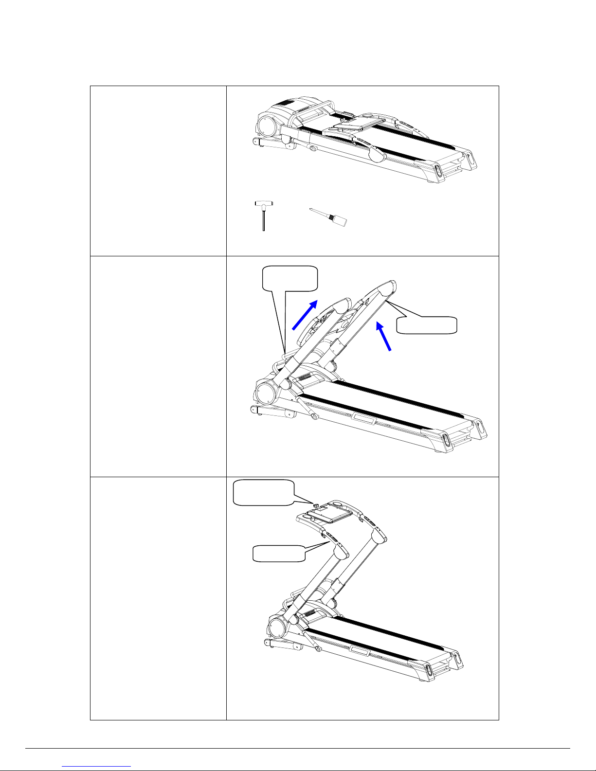
How to assemble?
STEP 1:
Take the machine and tool set
from the carton and put them
on flat ground.
PARTS LIST: FIG 1
1.Wrench
1PC
2.Silicon oil
1PC
STEP 2:
Hold the MIDDLE part of the
foldable bar with one
hand,and pull it upward as
FIG 2.
Meanwhile,hold the upright
tube with the other hand and
pull it upward as the
arrowhead direction.
FIG 2
STEP 3:
Uplift the handle bars with
both hands.It will be ok when
the sound “Kaka”is
heard.Then turn the switch
button in clockwise direction
and lift up the console in the
correct position.After
finishing,tighten the switch
button.
Assembly is finished.
Note: For advoiding from
injury,please pay attention to
the joint parts.
Upright tube
Foldable bar
Switch button
Handle bar
FIG 1
FIG 3
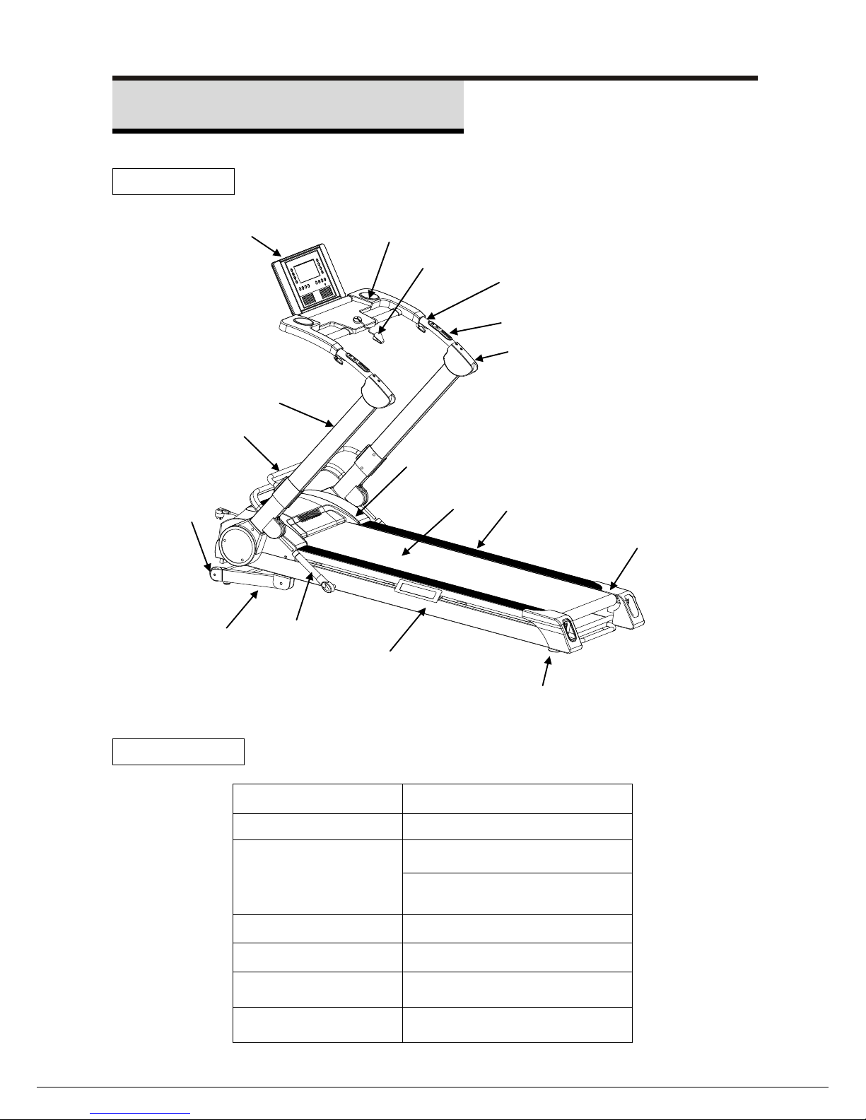
2
Product Intro
Structure
Parameter
Voltage
AC-220~240V 50~60Hz
Max load
130kg/290lbs
Size
Foldable: L1775*W800*H360mm
Assembly:
L1775*W800*H1385mm
Running area
1350*450mm
Max power
3.5HP
Incline
0~15%
Speed
1.0-18.0Km/h
FIG 4
Handle cover
Running belt
Cushion pad
Main frame
Incline weldment
Upright tube
Console
Odds and ends rack
Safety switch
Rear cover
Handle bar
Handle pulse sensor
Side rail
Motor cover
Foldable bar
Supporting wheel
Cylinder
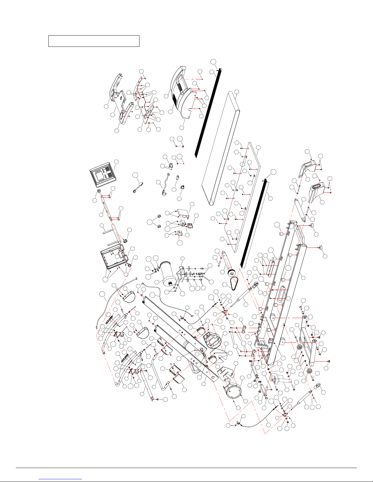
3
Exploded drawing
1
2
3
4
5
6
7
8
9
10
11
12
13
14
13
14
15
15
16
16
17
17
18
19
19
20
21
22
23
24
25
26
27
28
29
30
31
32
33
34
35
35
36
36
37
38
37
38
39
40
39
40
41
42
43
44
44
45
45
46
47
48
48
50
51
52
53
53
54
54
55
55
56
57
58
59
60
61
62
63
63
64
64
65
65
66
66
67
67
66
66
68
68
69
69
69
69
69
69
70
70
122
71
71
72
73
73
74
75
75
76
77
77
78
79
79
80
81
82
82
82
82
83
83
83
84
85
85
85
86
87
87
88
88
88
88
89
85
89
89
124
90
90
90
90
90
91
91
91
91
92
92
92
92
92
92
92
92
93
93
94
94
94
94
94
94
94
94
95
95
95
95
95
95
95
95
95
95
95
95
95
95
95
95
95
96
96
96
96
97
97
99
98
100
100
100
101
102
102
103
103
103
103
104
104
104
104
104
104
104
104
105
105
105
105
103
103
103
103
105
105
106
106
106
107
92
108
109
92
96
96
96
96
96
110
111
112
113
113
114
115
116
117
118
119
119
119
119
120
65
49
49
121
88
88
122
123
124
95
95
95
95
FIG 5
4
Itemized list
S/N Name Qty S/N Name Qty S/N Name Qty S/N Name Qty S/N Name Qty
1 Incline bracket 1 26 Incline motor 1 51 Right decoration part 1 76 Hex screw M10*45 1 101 Lock nut M8 2
2 Main frame 1 27 Upper console cover 1 52 Plastic cover 2 77 Hex screw M8*50 2 102 Lock nut M6 2
3 upright tube 1 28 Under console cover 1 53 Cylinder 2 78 Hex screw M8*15 2 103 Flat washer Φ10 8
4 Left handle bar 1 29 Left cross tube 1 54 Below Wire 2 79 Hex screw M8*65 2 104 Flat was her Φ8 12
5 Right handle bar 1 30 Middle cross tube 1 55 Upper Wire 2 80 Hex screw M8*45 1 105 Flat was her Φ6 6
6 Console bracket 1 31 Right cross tube 1 56 Controller 1 81 Hex screwM8*30 2 106 Flat washer Φ4 6
7 console tube 1 32 Cross bar board 1 57 Transformer 1 82 Hex screw M8*25 4 107 Lock washers for external teeth Φ4 1
8 foldable bar 1 33 Left console spindle cover 1 58 switch 1 83 Hex screw M8*20 8 108 Plastic sheet for wire fix 2
9 Left grounding tube 1 34 Right console spindle cover 1 59 Restoration switch 1 84 Hex screw M8*15 2 109 Line nip 1
10 Right grounding tube 1 35 Handle pulse 2 60 Power cable 1 85 Hex screw M6*15 4 110 Filter 1
11 Cross tube 1 36 Handle cover 2 61 Plug 1 86 Hexagonal screw M8*50 2 111 Inductor 1
12 U grip ring 2 37 Left foldable bar cover 2 62 Switch button 1 87 Cross screw M6*20 2 112 Magnet ring 2
13 Lock 2 38 Right foldable bar cover 2 63 Wheel 2 88 Cross screw M6*15 8 113 Cross screw ST4*20 2
14 Wire line hitch 2 39 Left urpright tube cover 2 64 Wheel base 2 89 Cross screw M5*15 4 114 Console wire 1 1
15 Wire connector 2 40 Right urpright tube cover 2 65 Small cushion pad 4 90 Cross screw M5*10 8 115 Console wire 2 1
16 Spindle ring 2 41 Left motor cover 1 66 Cushion pad 4 91 Cross screw M4*15 6 116 Optical sensor 1
17 Cylinder connector 2 42 Middle motor cover 1 67 Cover 4 92 Cross screw M4*8 19 117 Optical sensor bracket 1
18 Motor base 1 43 Right motor cover 1 68 Foam 2 93 Cross screw M4*12 2 118 Square cushipn 4
19 Cylinder switch 2 44 Upper cylinder cover 2 69 Sator for Side rail 6 94 Cross screw M6*25 8 119 Running board cushion 8
20 V belt 1 45 Under cylinder cover 2 70 Lock spring 4 95 Cross screw ST4*15 42 120 Cross screw M4*8 2
21 Running belt 1 46 Left rear cover 1 71 Screw 2 96 Cross screw ST4*10 15 121 Safety key 1
22 Running board 1 47 Right rear cover 1 72 Flat washer Φ35*Φ8.5*2.5 2 97 Cross screw ST4*10 4 122 Cylinder spring 2
23 Front roller 1 48 Side rail 2 73 Lubrication cover 2 98 Cross screw ST3*10 2 123 Cross screw ST4*15 8
24 Rear roller 1 49 Insertion strip 2 74 Hex screw M10*65 1 99 Cross screw ST2.9*6.5 2 124 Cross screw M5*15 4
25 Motor 1 50 Left decoration part 1 75 Hex screw M10*55 2 100 Lock nut M10 4
 Loading...