

TOORX TRX 9000 Instruction Manual

INSTRUCTION
Ed : 10/18 Rev : 00 Cod : TOXPRFTRX9000
3
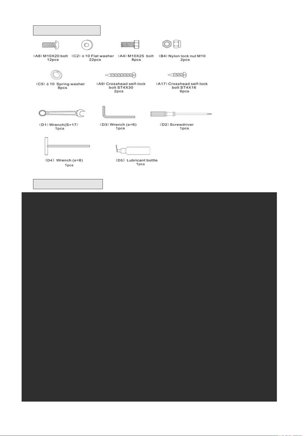
Hardware and tool
Explored drawing
4
Spare Parts List
No.
Description
Qty
No.
Description
Qty
1
Base frame
1
41
Signal wire A
3 2 Switch base frame
1
42
Signal wire B
2 3 Incline frame
1
43
Signal wire C
2 4 Left upright tube
1 5
Right upright tube
1 6
Handlebar and controller
1 7
Display screen
1
A1
Bolt M8X55
1 8 Oil pipe
1
A2
Bolt M10X95
1 9 Front roller
1
A3
Bolt M10X55
1
10
Rear roller
1
A4
Bolt M10X25
8
11
10 V belt
1
A5
Bolt M10X75
4
12
Running board
1
A6
Bolt M10X165
2
13
Running board cushion
8
A7
Half-round bolt M8X20
2
14
Rubber mat
8
A8
Half-round bolt M10X20
10
15
Running belt
1
A9
Crosshead self-lock bolt ST4X30
4
16
Universal wheel mat
2
A10
Half-round bolt M8X45
6
17
Left side rail
1
A11
Round bolt M10X60
2
18
Right side rail
1
A12
Round bolt M10X90
2
19
Non-slip colloidal particles
84
A13
Crosshead bolt M8X70
8
20
Position nut
6
A14
Crosshead bolt M3X8
2
21
Shock absorption mat
4
A15
Crosshead bolt M5X40
2
22
Baffle plate
1
A16
Crosshead bolt M5X20
2
23
Motor top cover
1
A17
Crosshead self-lock bolt ST4X16
27
24
Motor left cover
1 25
Motor right cover
1
B1
Hexagon Nut M8
8
26
Motor front cover
1
B2
Nylon lock nut M5
2
27
Left end cap
1
B3
Nylon lock nut M8
8
28
Right end cap
1
B4
Nylon lock nut M10
14
29
Middle end cap
1
C1
Flat washerφ8
8
30
Rear roller cap
2
C2
Flat washerφ10
24
31
Motor (AC)
1
C3
Big flat washerφ10
4
32
Incline motor
1
C4
Flat washerφ5
2
33
Frequency changer (AC)
1
C5
Spring washerφ10
10
34
Energency stop switch
1
C6
Spring washerφ5
2
35
Cymbiform switch
1
C7
Nylon Washerφ10
4
36
socket
1
D1
Wrench
1
37
wheel
2
D2
Screwdriver
1
38
cushion
2
D3
Wrench (s=6)
1
39
Nut cap
4
D4
Wrench (s=8)
1
40
Safety key
1
D5
Lubricant bottle
1

5
Assembly Instruction
Please make sure there’s enough space to install the treadmill and recommend 2 persons to
install it.
WAR NIN G: Don’t ins e rt the power wire unt il the treadmill was fully asse mbled.
Assembly tips:
1.In order to avoid instruction mistake, do not tighten bolt completely until the whole treadmill assembly
is finished.
2.This treadmill packaged for 2 cartons. #1 carton is main frame.#2 carton is Handlebar and controller.
1. Opening the package and take the
base frame out
Before the treadmill leave the factory,
the frame and pallet were fixed by
holders and bolts. Using wrench to
unscrew the bolts (total 4pcs bolts) on
frame, then take the base frame out.
(See figure 1)
2. Assembling left upright tube
A. Install the Left upright tube (4) to
base frame (1) using four sets of
bolt M10X25 (A4), Flat
washersφ10 (C2) by side.
(Attention: to align screw hole with
the upper surface). Make sure the
bolts to connect left upright tube
and base frame. (See figure 2)
B. In upper inner side, using one piece
Flat washer φ10 (C2) and one piece Nylon lock nut M10 (B4) to tighten. In upper outer side, using
Bolt M10X165 (A6) that was assembled on frame to tighten.(Attention: bolt head position is the front
underside. See figure 2-1)
3.Assembling right upright tube
A. Connect the Signal wire from right
upright tube to corresponding wires from
frame.
B. Install the Right upright tube (5) to
base frame (1) using four sets of bolt
M10X25 (A4), Flat washersφ10 (C2)
by side. (Attention: to align screw
hole with the upper surface). Make
sure the bolts to connect left upright
tube and base frame. (See figure 3)
C. In upper inner side, using one piece Flat washer φ10 (C2) and one piece Nylon lock nut M10 (B4) to

6
tighten. In upper outer side, using Bolt M10X165 (A6) that was assembled on frame to
tighten.(Attention: bolt head position is the front underside. See figure 3-1)
4. Assembling handlebar and controller
A. Connect the Signal wire from Right
upright tube to corresponding wires from
Handlebar.
B. Install handlebar and controller set(6) to
the Left/Right upright tube (4,5).
C. Connect handlebar and controller(6) to
the Left/Right upright tube (4,5) using 8 sets
of Half-round bolt M10X20(A8),Spring
washer φ 10(C5),Flat washer φ 10(C2).
(Attention: To align screw hole)(See figure 4)
5. Assembling display screen
A. Connect the signal wire from display
screen to corresponding wire from
controller. Crowding the extra wire into
controller.
B. Connect the display screen (7) to
handlebar and controller (6) using 4 sets
of Half-round bolt M10X20(A8),Flat
washersφ10(C2).(Attention: To align
screw hole)(See figure 5)
6. Assembling motor left & right cover
A.Tighten all the assembling bolt.
B.Install motor left cover (24) to left motor
cover (23) of base frame (1) using 1pcs
Crosshead self-lock bolt ST4X30 (A9) in
front and 3pcs Crosshead self-lock bolt
ST4X16 (A17) to tighten.
C.Install motor right cover(25) to left motor
cover(23) of base frame (1) using 1pcs
Crosshead self-lock bolt ST4X30 (A9) in
front and 3pcs Crosshead self-lock bolt
ST4X16(A17) to tighten.(See figure 6)
 Loading...