

TOORX TRX 50 S EVO Instruction Manual
Ed : 03/17 Rev : 00
INSTRUCTION
3
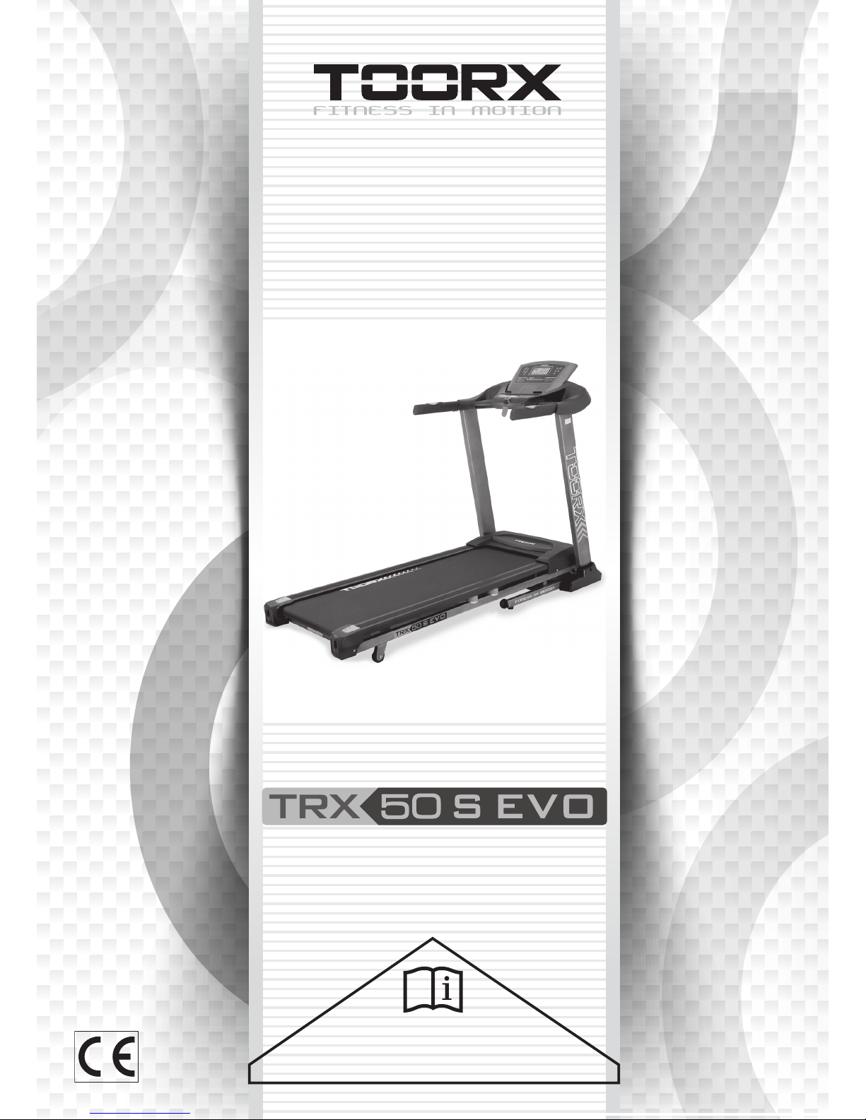
Carton Contents
Hardware pack
68# M8¡Á20mm Allen Bolt (Qty4)
87# ?8mm Spring Washer (Qty14)
84# ?8mm Washer (Qty14)
5# Allen Wrench (Qty1)
Multi Wrench (Qty1)
6# Allen Wrench (Qty1)
54# M8¡Á90mm Allen Bolt (Qty4)
71#
ST4.8¡Á15mm Philip Screw
w/washer(Qty2)
66# M8¡Á80mm Allen Bolt (Qty2)
57# M8¡Á15mm Allen Bolt (Qty4)
20.
Left Mast Cover
Lubricating Oil
21.
Right Mast Cover
45.
Safety Key
3.
Left Console Mast
4.
Right Console Mast
Main Frame
Hardware pack
Console
52.
Power cord
4
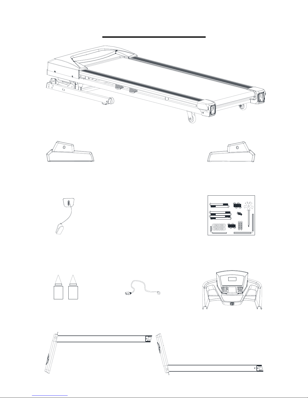
Hardware Pack Contents
68
20mm Allen Bolt × 4
71 87
66 84
8mm Washer
× 14
80mm Allen Bolt × 2
8mm Spring Washer
× 14
15mm Phillips Screw × 2
5# Allen Wrench × 1
6# Allen Wrench
×
1
Multi Wrench
×
1
54
90mm Allen Bolt × 4
15mm Allen Bolt × 4
57
5
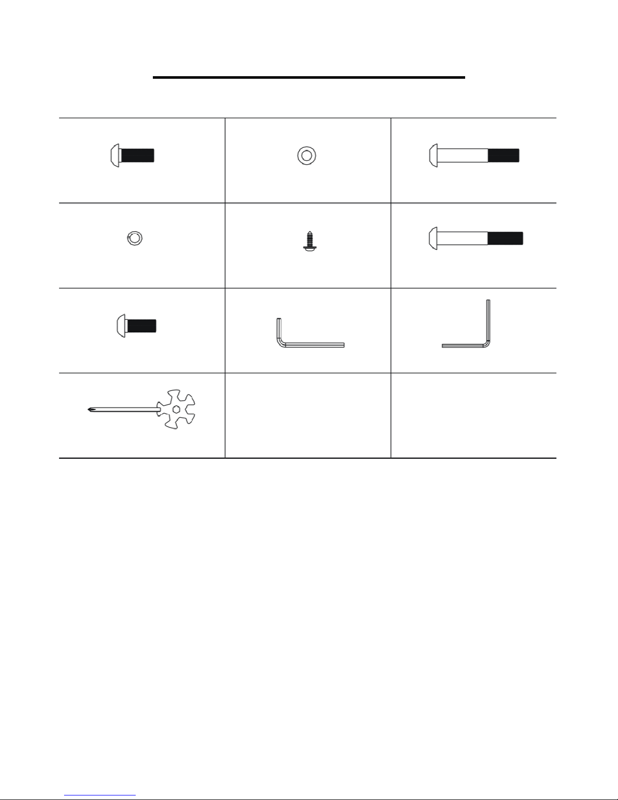
Product Overview
Pulse Sen
sor
Console Mast
Cover
Transport Wheel
Handle Grip
Safety Key
Console Mast
Motor Cover
Side Rail
End Cap
Running Deck
6
Assembly Instructions
Step 1
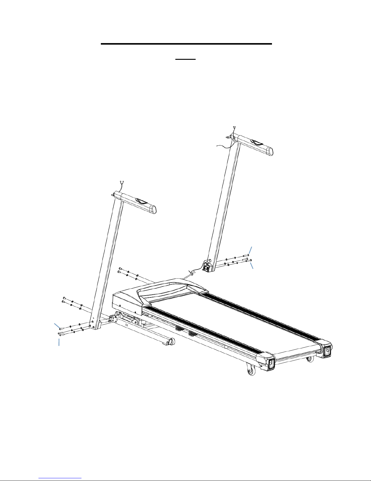
1.1 Thread the Main Wire from the bottom of the Right Console Mast (4) to the top and through the opening.
1.2 Attach Left Console Mast (3) and Right Console Mast (4) to the Base Frame (1) using 4 x M8 x 15mm
Allen Bolts (57), 2 x M8 x 80mm Allen Bolts (66), 4 x M8 x 90mm Allen Bolts (54), 10 x 8mm Spring
Washers (87) and 10x 8mm Washers (84).
3
1
4
54
84
87
66
87
84
84 87 54
66
87
84
Main wire
87
87
57
57
84
84
7
Step 2
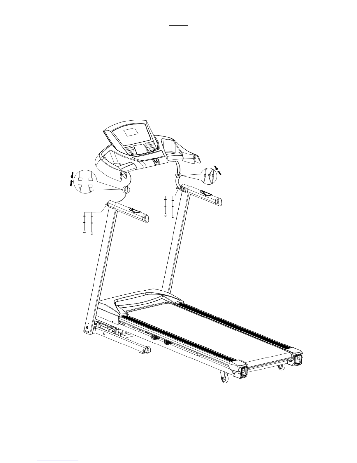
2.1 Take the console and connect the wires from the Left Console Mast (3) and Right Console Mast (4) to the
wires from the console, there will be two wires from the Left Console Mast (3) and three from the Right
Console Mast (4).
2.2 Insert the connected wires into the handles of the Left Console Mast (3) and Right Console Mast (4) to
ensure they don’t get pinched between the console and frame of the treadmill.
2.3 Attach the console to the Left Console Mast (3) and Right Console Mast (4) using 4 x M8 x 20mm Allen
Bolts (68), 4 x 8mm Spring Washers (87) and 4 x 8mm Washers (84).
Console
B
3
4
A
A’
B’
68
84
87
84
87
68
8
Step 3
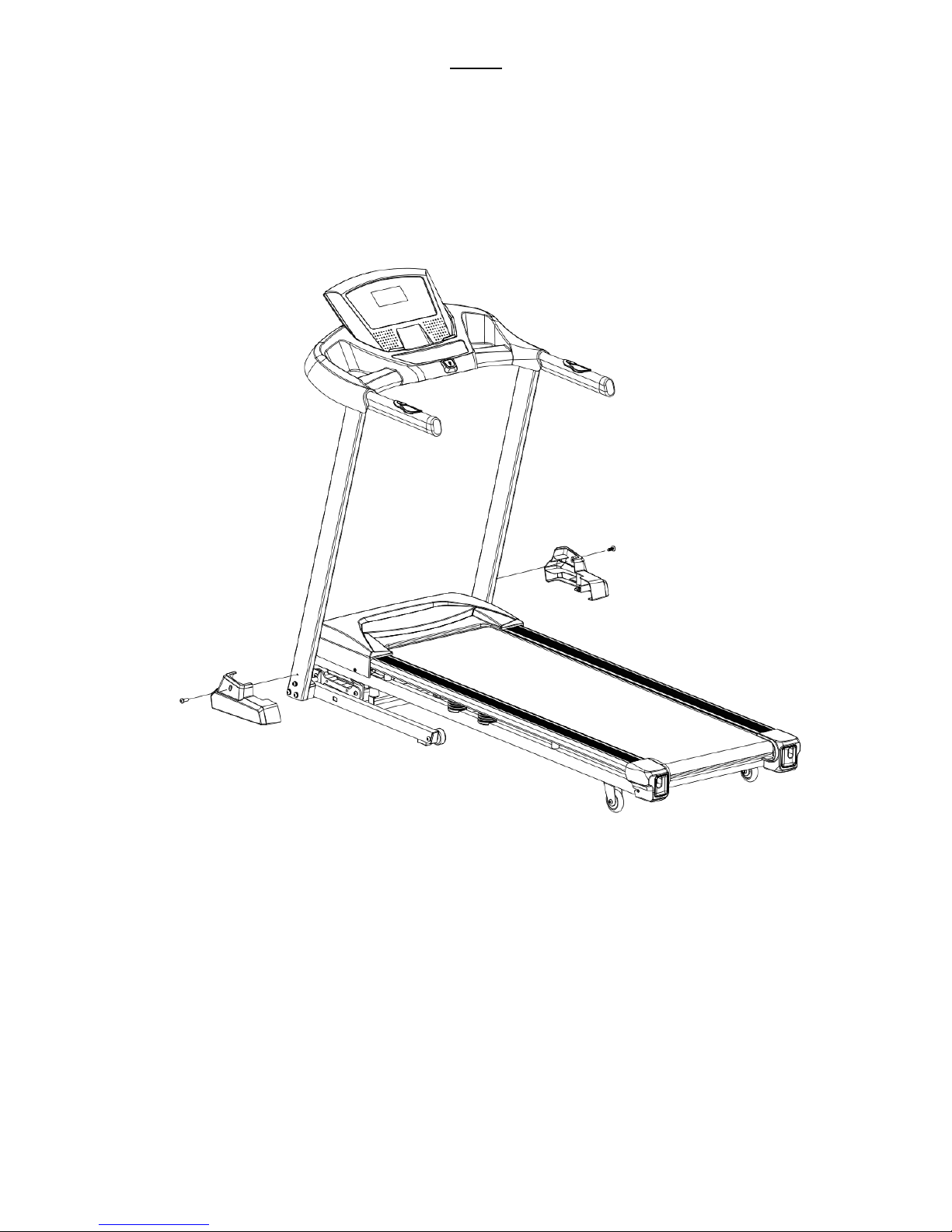
3.1 Attach the Left Mast Cover (20) and Right Mast Cover (21) by inserting the fastener located on the end of
the mast covers into the groove on the Base Frame (1).
3.2 Secure the Left Mast Cover (20) and Right Mast Cover (21) in place using 2 x ST4.8 x 15mm Dome Head
Philips Screws (71) to attach them to the Left Console Mast (3) and Right Console Mast (4).
20
3
21
4
Fastener
Groove
1
71
71
 Loading...