


INSTRUCTION
GRLDTOORXSRX70S
00
09/18
Ed : Rev : Cod :
4
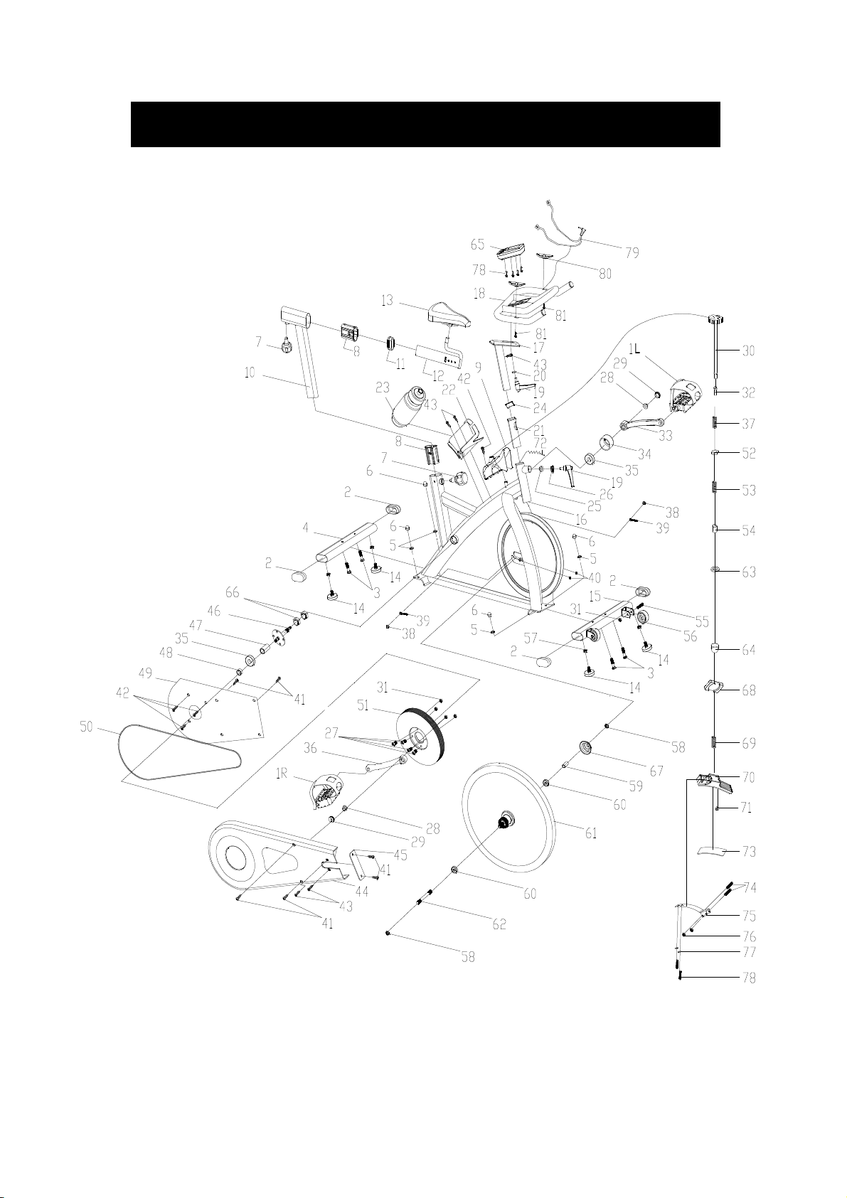
EXPLODED-VIEW & PARTS LIST:

5
NO NAME
(H=16mm)
(H=16mm)
1 PEDAL 1
2 END CAP1 4 80*40*1.5
3 CARRIAGE BOLT 4 GB/T 12-1988 M8*52
4
5 FLAT WASHER 8 GB/T 95-2002 8
6 DOMED NUT 4
7 SPRING ADJUSTMENT KNOB 2 φ50*82 (M16*1.5)
8 PLASTIC SLEEVE 1 2 70*30*1.5
9 KNOB COVER 1 177X142X187
10
11 END CAP 2 1 70*30*1.5
12 SEAT POST 1 WELDING
13
14 STOPPER 4 φ32*37/(M8X25)
15
16
17 HANDLEBAR POST 1 WELDING
18 HANDLE BAR 1 WELDING
19 L SHAPE KNOB 2 M10*25
20 FLAT WASHER 1 1 φ45*φ10.5*5
21 PLASTIC SLEEVE 2 1 38*38*1.5
22 B0TTLE HOLDER 1 117*85*90
23 B0TTLE 1 XS-003(1#) 500ML
24 END CAP 3 1 38*38*1.5
25 FIXING SHAFT 1 φ22*23 (V)
26 FIXING NUT 1 Q235/32*12
27 BOLT 4 GB/T 70.2-2000 M8*15
28 FIXING NUT 1 2 GB/T 6177.2-2000 M10*1.25
29 CRANK END CAP 2 φ23*7.5
30 KNOB 1
31 LOCK NUT 6 GB/T 889.1-2000 M8
32 BUSHING 1 φ18*φ10*10
33 LEFT CRANK 1 170*27
34 CRANK COVER 1 φ56*28
35 BEARING 2 6004ZZ
36 RIGHT CRANK 1 170*27
37 SPRING 1 1 δ1.8X40
38 FIXING NUT 2 2
39 FIXING BOLT 2 M6*57
40 NUT 2 GB/T 889.1-2000 M6
REAR STABILIZER
VERTICAL SEAT POST
SEAT
FRONT STABILIZER
MAIN FRAME
QUANTITY SPEC
JD-301(9/16"
1 WELDING
GB/T 802-1988 M8
1 WELDING
1 DD-2681
1 WELDING
1 WELDING
φ40*180 (φ10
GB/T 802-1988 M12X1.25
)
)

6
NO NAME
41 SCREW 1 8 GB/T 845-1985 ST4.2*19
42 SCREW 2 6 GB/T 15856.1-2002 ST4.2X19
43 SCREW 3 2 GB/845-85 ST4.8X13
44 OUTER CHAIN COVER 1 654*263*49 (507g)
45 LITTLE CHAIN COVER 1 108*37*3 (7g)
46 AXIS 1 φ20*162
47 LONG FIXING TUBE 1 φ25*φ20.5*41
48 SHORT FIXING TUBE 1 φ25*φ20.5*9
49 INNER CHAIN COVER 1 451*260*2 (250g)
50 BELT 1
51 BELT WHEEL 1 φ200*24
52 FIXING NUT 2 1
53 SPRING 2 1 φ1.0X55
54 SHORT FIXING TUBE 1 φ14*φ10.2*25.5
55 BOLT 2 GB/T 5780-2000 M8*40
56 WHEEL 2 φ50*23
57 NUT 4 GB/T 41-2000 M8
58 FIXING NUT 2 2 M12X1.25 H=6
59 FIXING TUBE 1 φ16*φ12.1*35
60 BEARING 2 6001ZZ
61 FLYWHEEL 1 HT250/φ453*72
62 FLYWHEEL SHAFT 1 φ12*160
63 FLAT WASHER 1 1 GB/T 95-2002 6
64 DOMED NUT 1 1 GB/T 802-1988 M6
65 COMPUTER 1
66 FIXING NUT 2
67 FLYWHEEL COVER 1 φ59*35
68 SPRING COVER 1 32*23*2
69 SPRING 3 1 φ2.2
70 PLASTIC FRAME 1 200*47*30
71 LITTLE PLASTIC 1 14*9*14
72 SENSOR 1 SR-202
73 WOOLLY BLOCK 1 113*25*6
74 BOLT 1 2 GB/T 5780-2000 M5*30
75 SPRING BRAKE 1 δ1.0
76 LOCK NUT 2 GB/T 889.1-2000 M5
77 SPRING WASHER 1 2 GB/T 859-1987 5
78 BOLT 2 2 GB/T 5780-2000 M5*10
79 PULSE WIRE 1 L=800
80 PULSE 2
81 SCREW 5 2 GB/845-85 ST4.2X25
QUANTITY SPEC
5PK53
16X16X5 (M10
ST-6527(ST-7607)
27*M20*1(5mm
)
)

7
ASSEMBLY INSTRUCTION:
1.PREPARATION:
A. Before assembling make sure that you will have enough space around the item.
B. Use the present tooling for assembling.
C. Before assembling please check whether all needed parts are available (at the above
of this instruction sheet you will find an explosion drawing with all single parts (marked
with numbers) which this item consists of.
2.ASSEMBLY INSTRUCTION:
:
FIG.1
FIG.1:
Attach the Front Stabilizer (pt.15)
to the Main Frame (pt.16) using two
sets of Ø8 Flat Washers (pt.5), M8
Domed Nut (pt.6) and M8*52 Carriage
bolt (3).
Attach the Rear Stabilizer (pt.4) to the
Main Frame (pt.16) using two sets of
Ø8 Flat Washers (pt.5), M8 Domed Nut
(pt.6) and M8*52 Carriage bolt (3).
FIG.2:
Slide the seat post (12) into the vertical
Seat post (10) and, at the desired
position, align holes and fix in place with
the Spring Adjustment Knob (pt.7)
fix the Seat (13) to the seat post (12) as
shown. Insert the vertical Seat Post (10)
into the main frame (16) and line up the
holes. Secure the saddle in position
with the Adjustment Knob (7). The correct
height for the seat can be adjusted after
the bike is fully assembled.
. Now
FIG.2

8
FIG.3
FIG.4
FIG.3:
Slide the Handlebar Post (pt.17) into the
handlebar post housing on the main
frame(pt.16). You will have to slacken the
knurled section of the L Shape Knob
(pt.19) and pull the knob back and then
select the desired height. Release the
knob and retighten the knurled portion.
Then fix the Handlebar (pt.18) with a flat
washer 1 (20) and L Shape knob (19)
ATTENTION: YOU SHOULD FIX
THE HANDLEBAR TIGHTLY
Fix the Computer (pt.65) onto the
Computer Holder of handlebar
(pt.18) with bolt(pt.78)
Insert the sensor cable (a) into the
bushing located on the backside of the
computer (65).
FIG.4:
The Pedals (pt.1 L & pt.1 R) are
marked "L" and "R" - Left and Right.
Connect them to their appropriate
crank arms. The right crank arm is on
the right- hand side of the cycle as you
sit on it.
Note that the Right pedal should be
threaded on clockwise and the Left
pedal anticlockwise.

9
A.) Adjusting the Tension:
Increasing or decreasing the tension
allows you to add variety to your
workout sessions by adjusting
the resistance level of the bike.
To increase tension and increase
resistance (requiring more strength
to pedal), turn the Emergency
Brake & Tension Control Knob (#30)
to the right.
To decrease tension and increase
resistance (requiring less strength to
pedla), turn the Emergency
Brake & Tension Control Knob (#30)
to the left.B.) Using the Emergency
Brake Function:
The same knob that allows you to
adjust the tension of the bike also
doubles as the Emergency
Brake. Use this safety feature in any
situation where you would need to
get off the bike and/or
stop the bike’s flywheel.
To use the Emergency Brake
function in any situation you would
need it in, firmly press down
on the Emergency Brake & Brake
Control Knob (#30).

GARLANDO SPA
Via Regione Piemonte, 32 - Zona Industriale D1
15068 - Pozzolo Formigaro (AL) - Italy
www.toorx.it - info@toorx.it
 Loading...