

Page 1
Ed : 03/17 Rev : 00
INSTRUCTION
Page 2
2
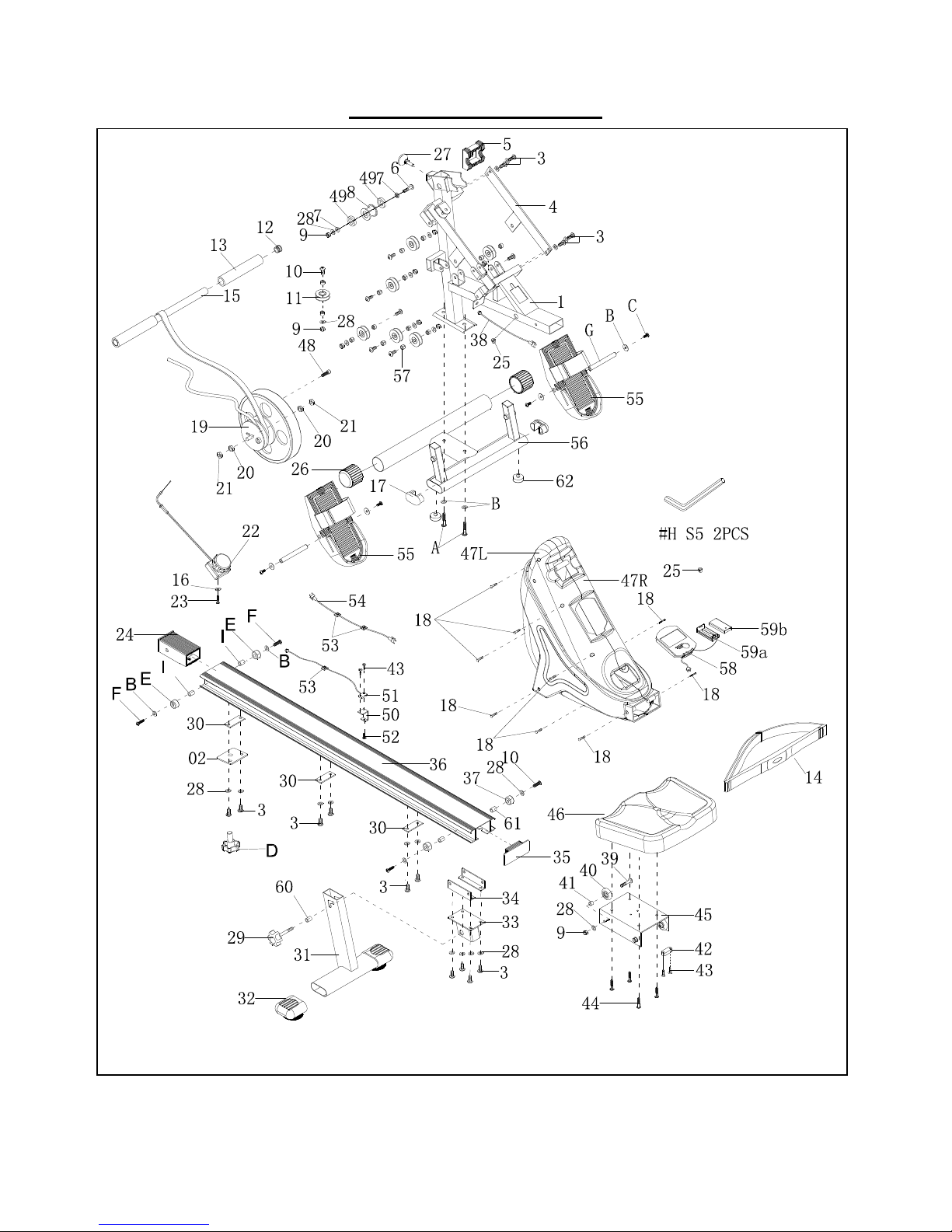
EXPLODED DIAGRAM
Page 3

3
PART LIST:
NO. DESCRIPTION Q'TY
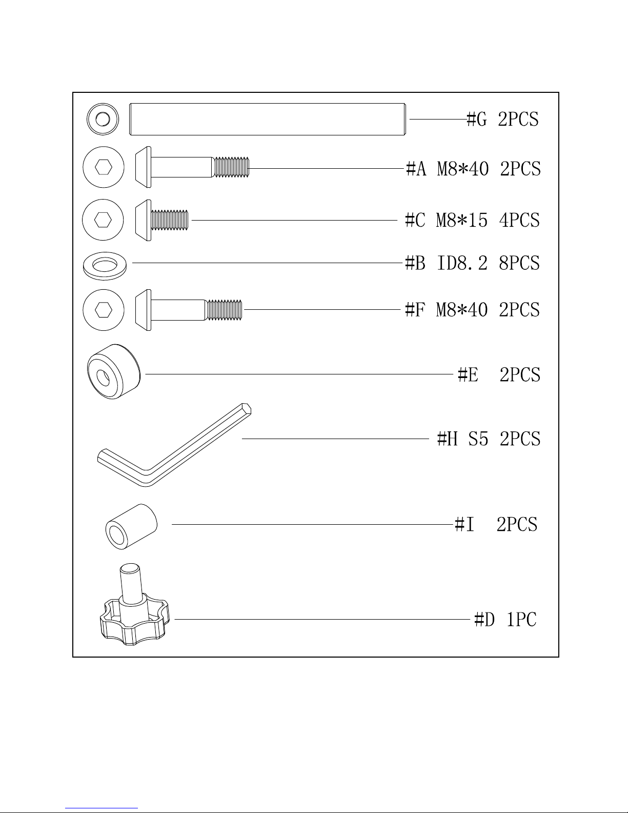
A Bolt M8x40 2
B Washer 8
C Bolt M8x15 4
D Knob 1
E Rubber Cushion 2
F Bolt M8x40L 2
G Axle 2
H Wrench S5 2
I Casing 2
1 Main Frame 1
2 Plate 1
3 Bolt M8*15 14
4 Enforcement plate 1
5 Plastic pad 1
6 Bolt M8x55 1
7 Sleeve 2
8 Plastic wheel 1
9 Nut M8 12
10 Bolt M8*40 9
11 pully 7
12 End cap 2
13 Grip 2
14 Heart rate transmitter 1
15 Rowing handle bar 1
16 Washer 1
17 End cap 2
18 Bolt M4*20 13
19 Magnetic flywheel 1
20 Nut M10 S17 2
21 Nut M10 S15 2
22 Tension Knob and cable 1
23 Screw M5*15 1
24 Hollow bushing 1
25
STRAIN RELIEF BUSHING
2
26 End cap 2
27 Knob 1
Page 4

4
28 Washer M8 28
29 Knob M8 x40 1
30 Enforcement plate 3
31 Rear Stabilizer 1
32 End cap 2
33 Fasten plate 1
34 Fasten plate 2
35 End cap 1
36 Main Rail 1
37 Rubber Cushion 2
38 Sensor wire of computer 1
39 Bolt M8*30 4
40 Wheel 4
41 Sleeve 4
42 Magnet 1
43 Screws M3*10 4
44 Bolt M6*12 4
45 Saddle Support frame 1
46 Saddle 1
47R Right plastics Cover( right) 1
47L Left plastics Cover(left) 1
48 Bolt M6*30L 1
49 Bearing 6900Z 2
50 Sensor fasten plate 1
51 Sensor 1
52 Screw M5*10 1
53 STRAIN RELIEF BUSHING 3
54 Sensor wire of computer 1
55 Pedal 2
56 Front Stabilizer 1
57 Sleeve 14
58 Computer 1
59 Battery bracket 1
59 Cover of battery bracket 1
60 Casing:OD12.7*ID8.3*5L 1
61 Casing 2
62 Cushion 2
63 Washer 1
64 End cap 2
Page 5
5
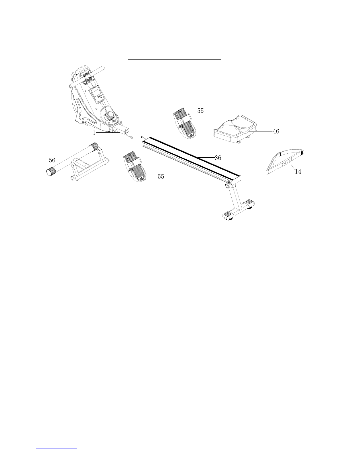
EXPLODED DIAGRAM
Page 6
6
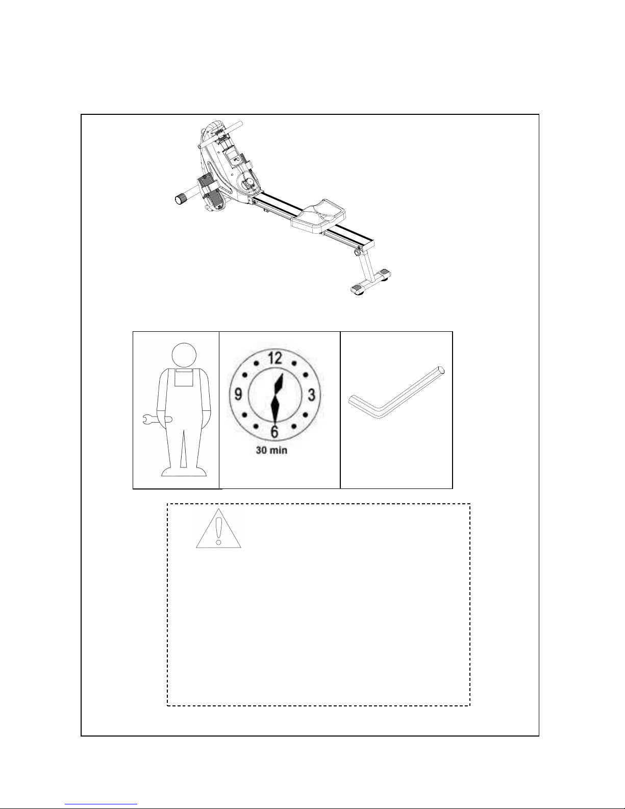
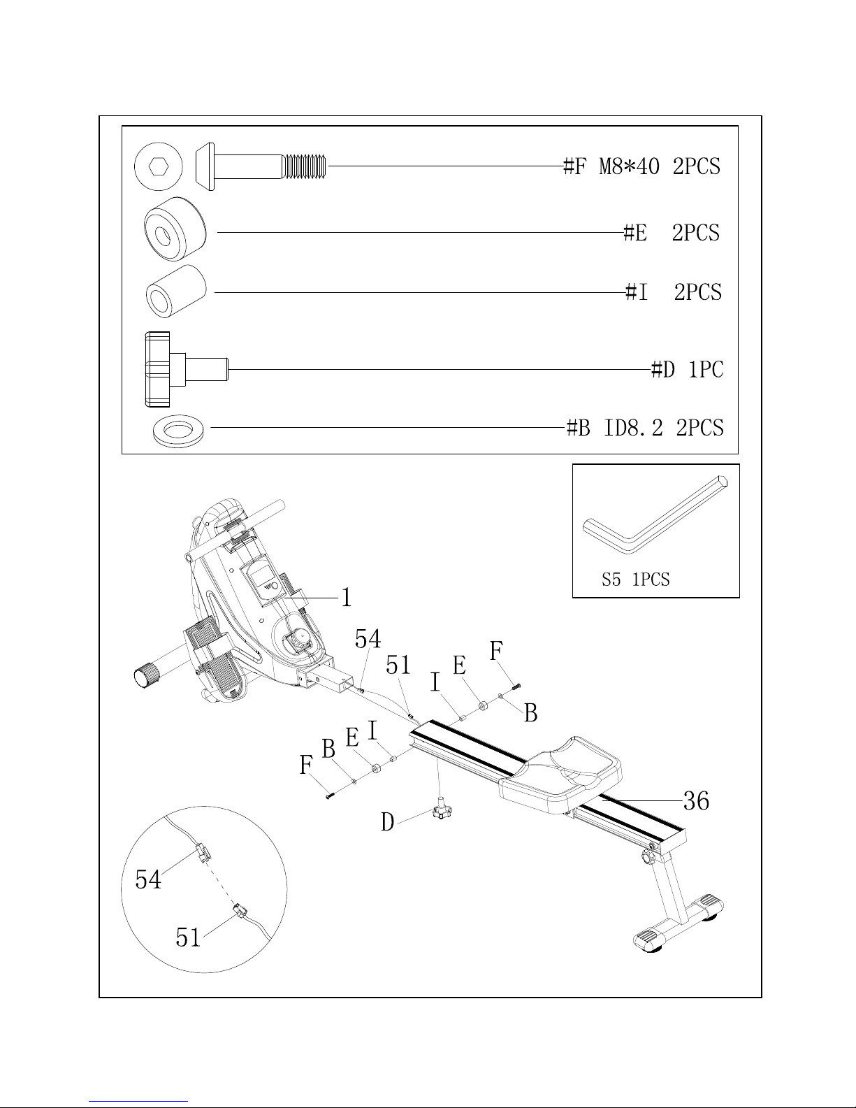
Assembly Information
NOTICE
• Read this manual before assembly
• Recognize the spare parts first.
• Check the hardware.
• Ensure that you have the right tool.
• Prepare an area to assemble.
• Follow the instruction accordingly.
• Never force the joints
• Periodically tighten the joints
• Keep this manual with you.
S5 2PCS
Page 7
7
II. Identify your hardware
Page 8
8
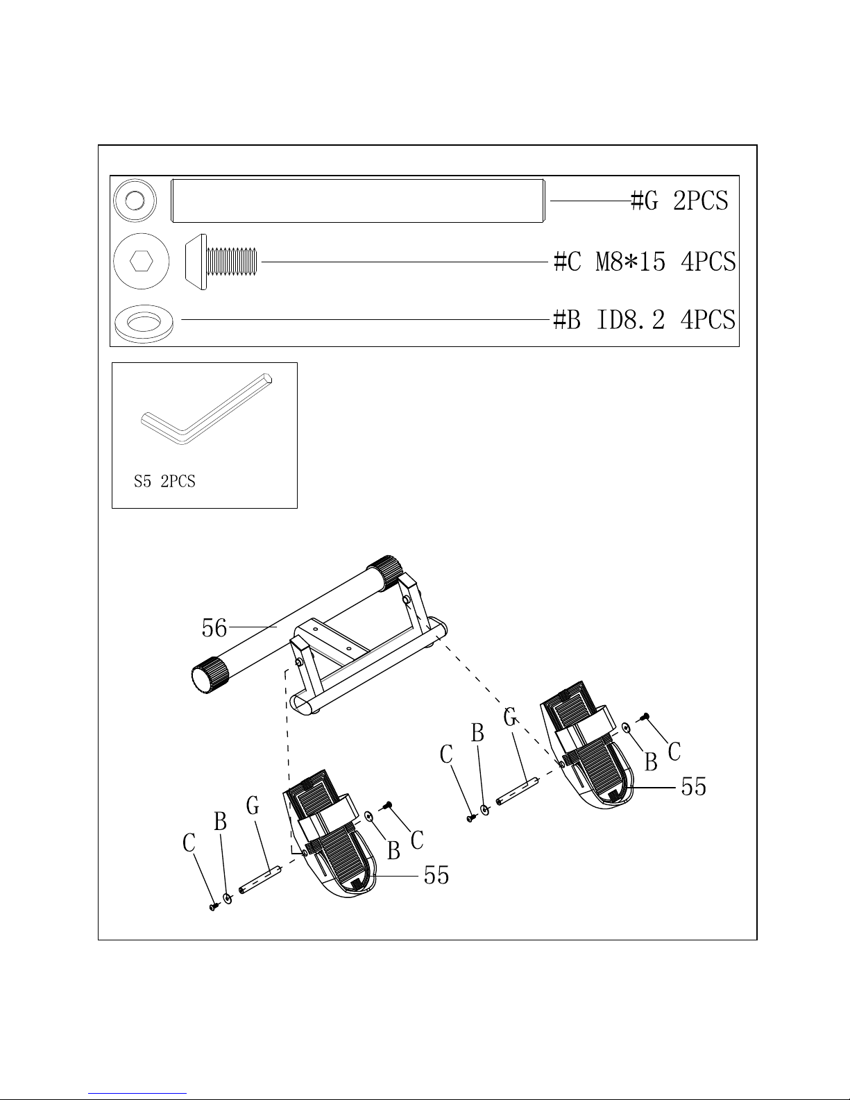
Assembly Steps
STEP 1:
Page 9
9
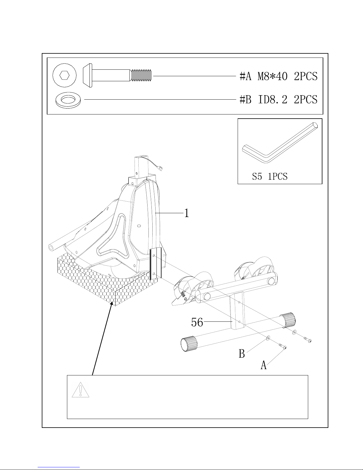
STEP 2:
Upright the main frame onto the Style foam to prevent from scratch on the
plastic cover while mounting the front stabilizer to the main frame.
Page 10
10
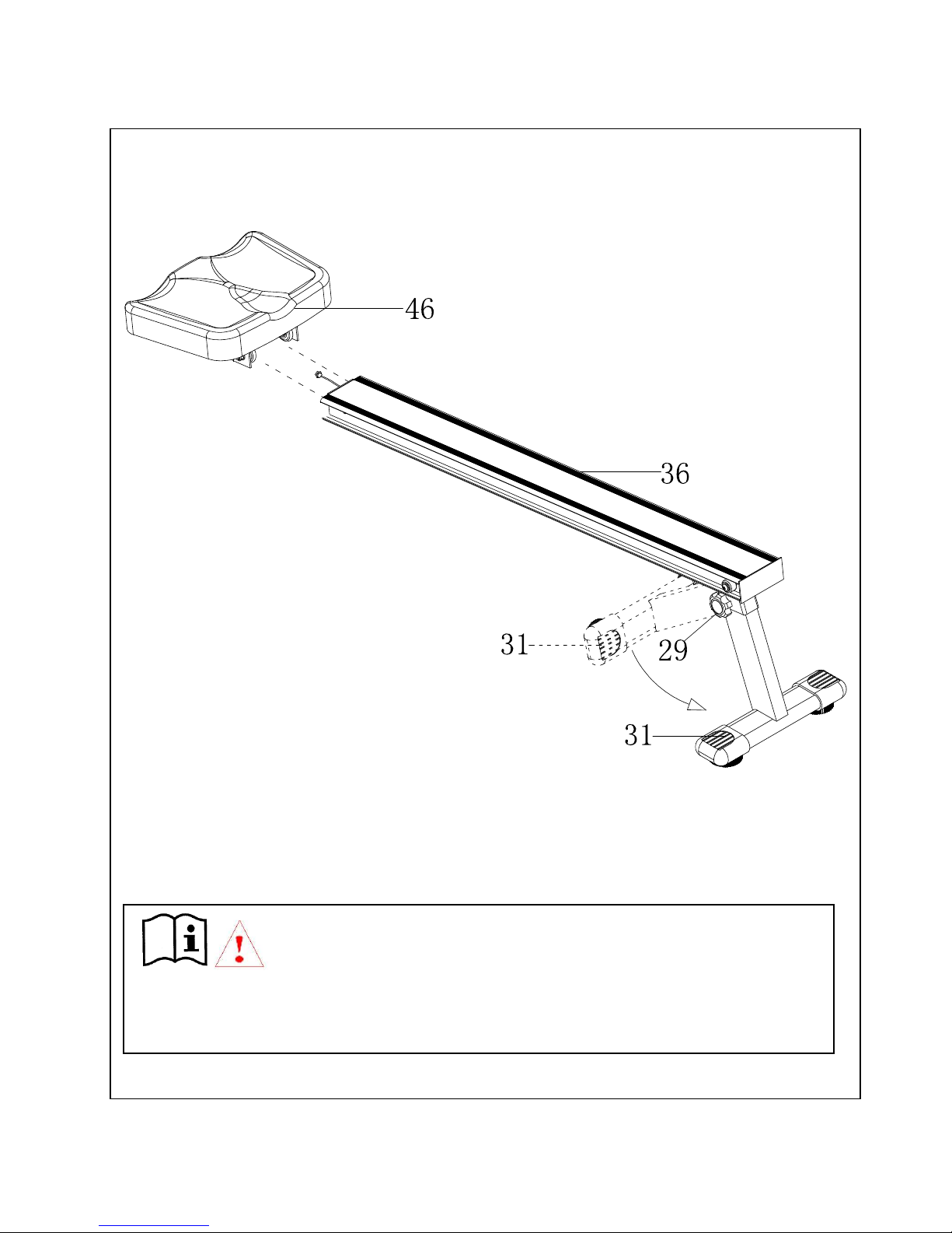
STEP 3:
Loosen the knob (#29), and pull out the rear stabilizer (#31) as the direction of the arrow
shown in Figure. Then lock the knob(#29) tightly in order to prevent any accident.
Page 11
11
STEP 4:
Page 12
12
STEP 5:
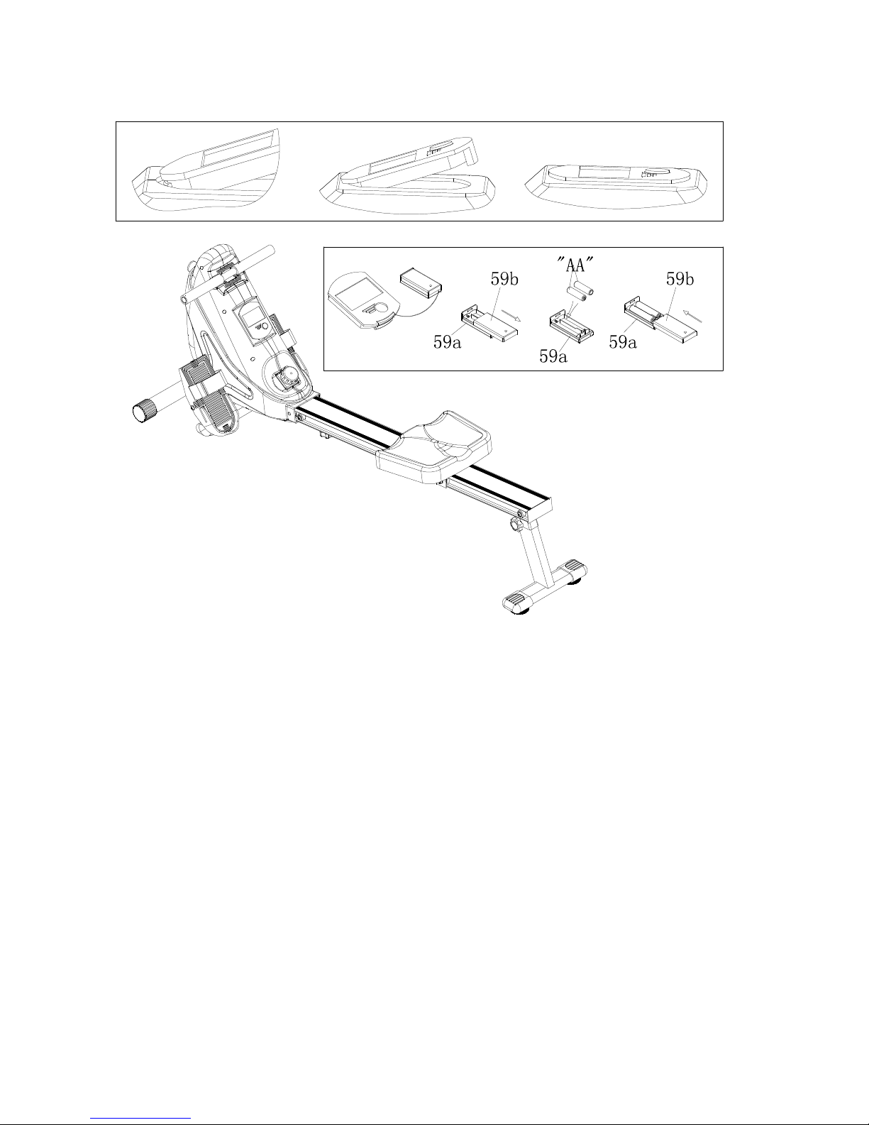
BATTERY:
1. The monitor uses on “AA” battery. You can replace the battery through the back of the
unit.
2. Battery must be correctly positioned and make sure the battery spring is properly
contact with battery.
3. If the display is illegible or only partial segment appeared. Please take out the battery
and wait for 15 seconds, then reinstall it.
ADVICE FOR HANDLING BATTERIES
1 Remove the batteries when they are exhausted or if you do not use the product for an
extended period of time in order to avoid hazards through leaking batteries.
2 Do not recharge batteries nor dissemble or throw then into fire. Danger of explosion!
3 Pay attention to the polarity (+) and (-). Always replace all the batteries; do not mix old
and new batteries, or different battery types.
4 Use preferably alkaline batteries, as they have a longer operation time then usual
zinc-coal-batteries.
5
A change of batteries is necessary when the display becomes weaker or completely
faded.
Page 13
13
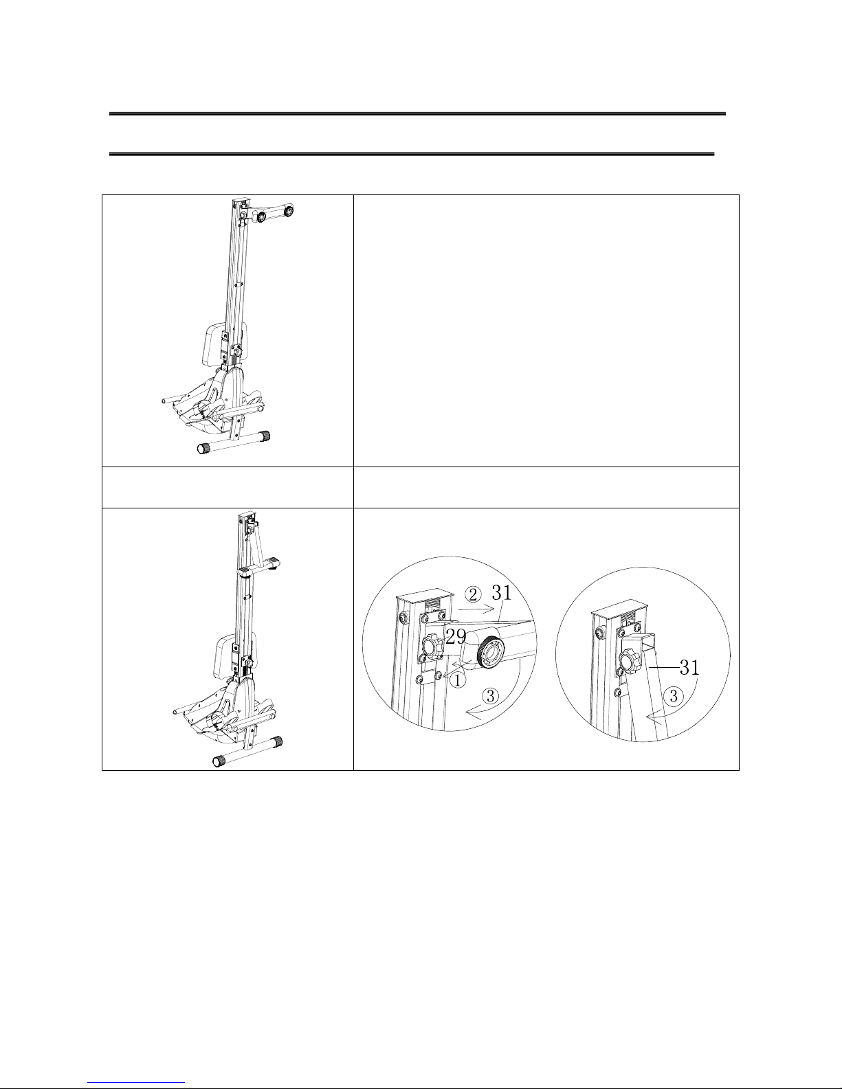
STORAGE WAY
HOW TO FOLDING THE ROWING MACHINE
Store your
machine
in a dry area away from children and
high traffic areas as the illustration shown. be sure it is secure
and cannot fall forward onto small animals or children.
2 Loosen the knob (#29) first, then pull the rear stabilizer (#31)
out and fold down as follow illustration.
Page 14
14
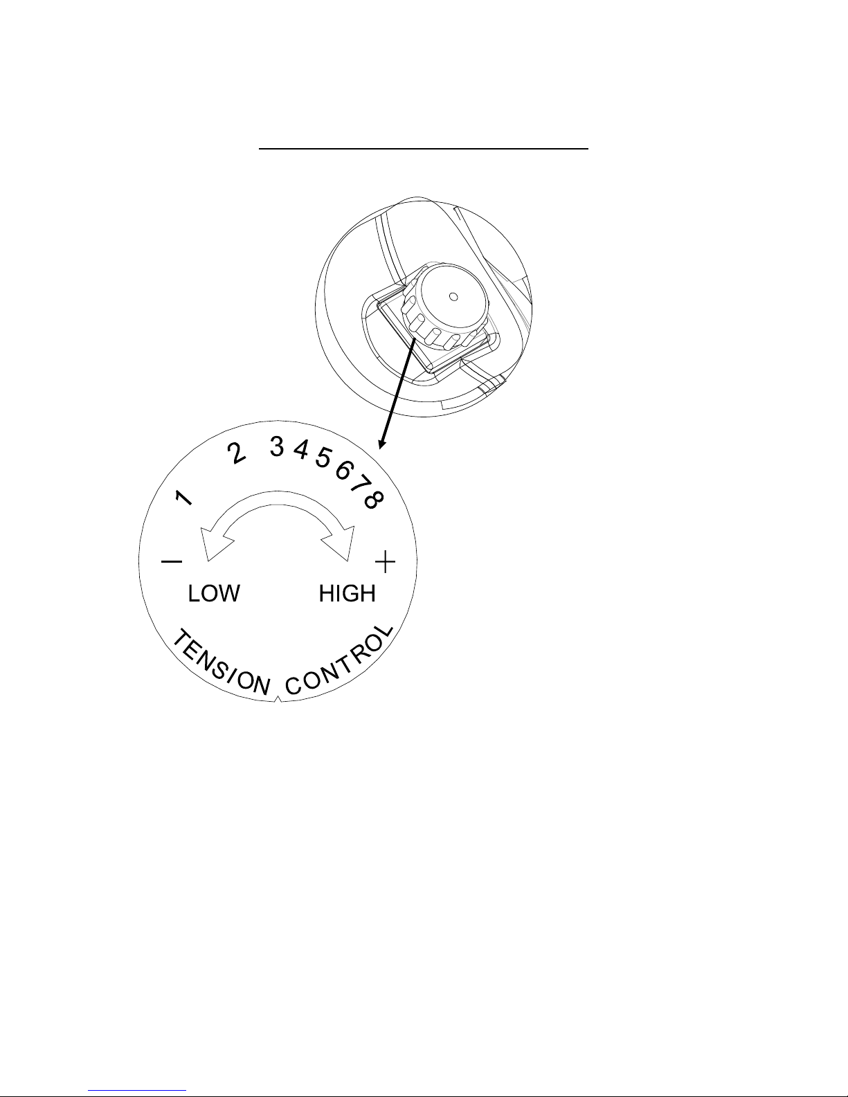
Tension Knob adjustment:
You could adjust the tension for varied resistance as below:
NOTE: You should begin your “Exercise Period” at the resistance level and speed to suit
your needs. Remember to start out slow and easy and work your way up to the fitness level
you desire.
Page 15
15
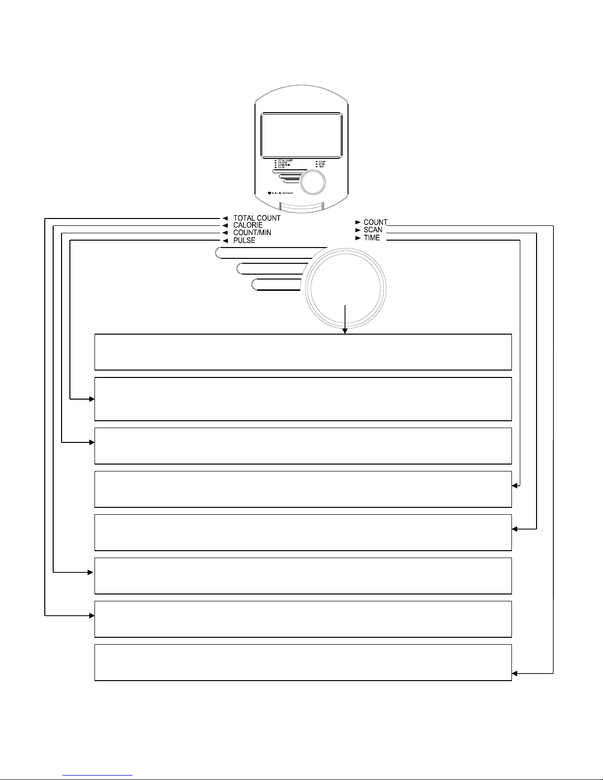
THE OPERATION OF COMPUTER
MODE: Allow to select each function
SCAN:Automatically scans each function sequence of the 5 functions.
CALORIE: Accumulates calorie consumption during exercise.
COUNT/MIN: It displays how many strides in every minute.
TOTAL COUNT: It Shows the total number of stokes performed.
TIME: It indicates how long you have exercised
COUNT: It accumulates how many strides during workout sessions
PULSE: It indicates your pulse rate during the workout. It is just a
reference data.
Page 16
16
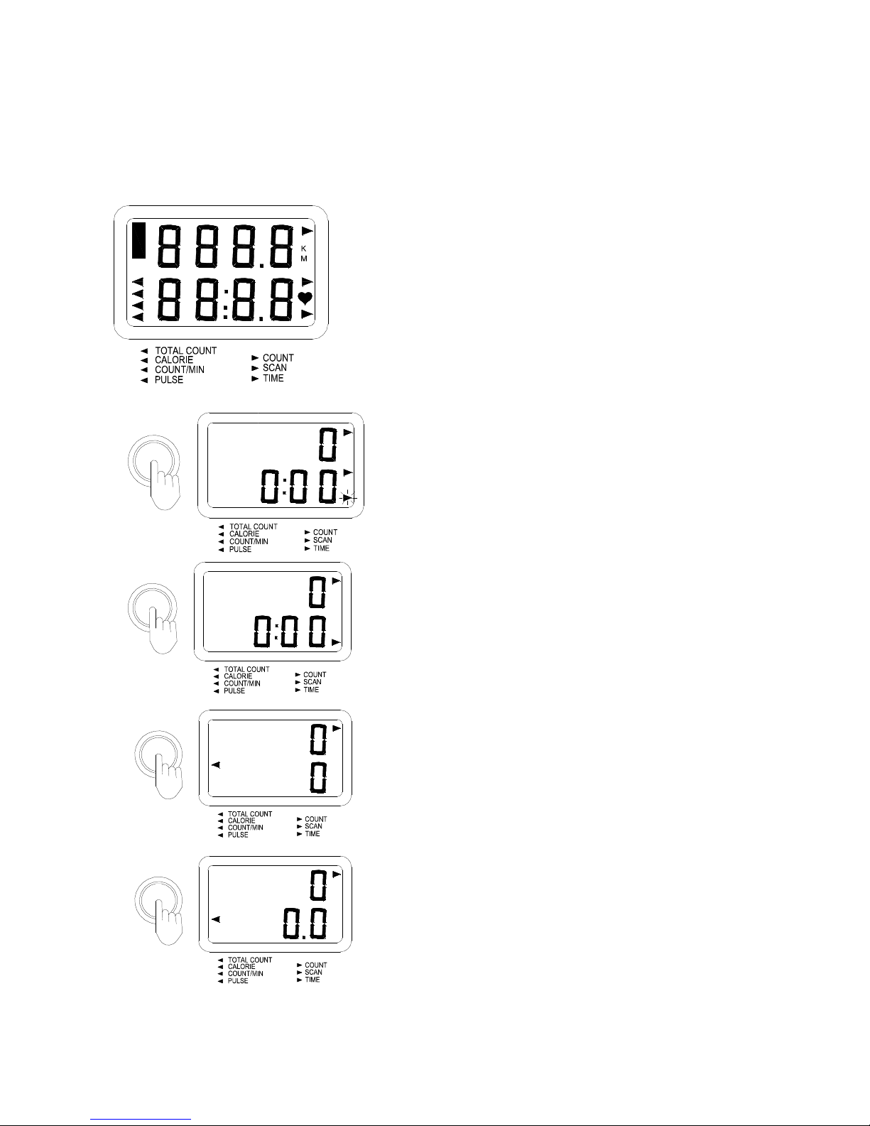
II. “MODE” button:
This button lets you select and lock on to a particular display function you want.The monitor will be
reset by changing battery or keep pressing the button for 3~4 seconds.
III. During or after the exercise, press the “Mode” function to select the display function like SCAN,
TIME, TOTAL COUNT, CALORIES, COUNT/MIN,
THE COMPUTER WILL DISPLAY THE FUNCTION “COUNT” AT ALL TIMES.
Keep pressing the button “MODE” to select the function
"SCAN": It automatically shows each function sequence
of the time ,total count , calorie, count/min, pulse
Keep pressing the button “MODE”, until the pointer
locks on to the function " TIME" : It means the duration
of the exercise
Keep pressing the button “MODE”, until the pointer
locks on to the function " TOTAL COUNT" : It Shows the
total number of stokes of the user has performed.
Keep pressing the button “MODE”, until the pointer
locks on to the function "CALORIES": The window tells
the consumption of calorie during the workout
Page 17
1
7
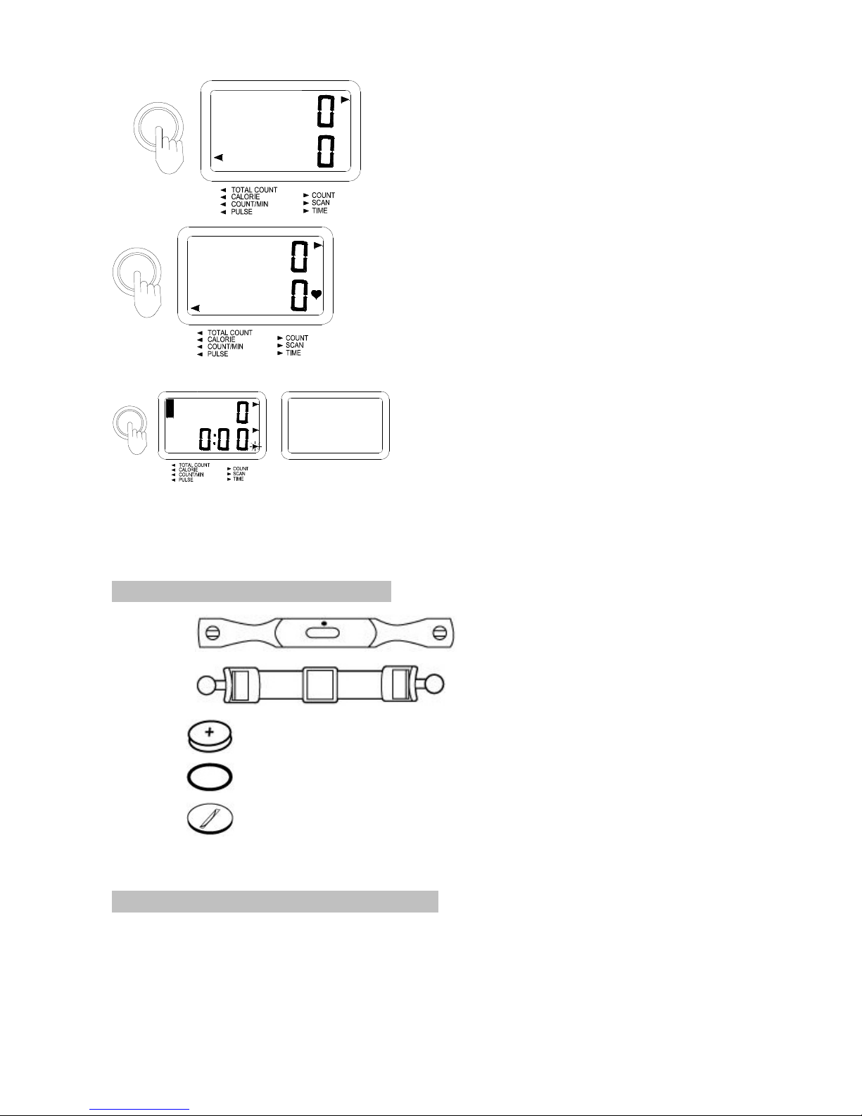
Keep pressing
the button “MODE”, until the pointer
locks on to the function "COUNT/MIN". It tells how many
steps you exercise per minute.
Keep pressing
the button “MODE”, until the
pointer
locks on to the function "PULSE ".
WARNING!
Heart rate monitoring systems may be inaccurate.
Over exercise may result in serious injury or death.
If you feel faint stop exercising immediately
When the exercise is finished and the apparatus is left
alone for some minutes, the meter will shut off
automatically
HEART RATE TRANSMITTER OPTIONAL
ACCESSORIES & ATTACHMENT
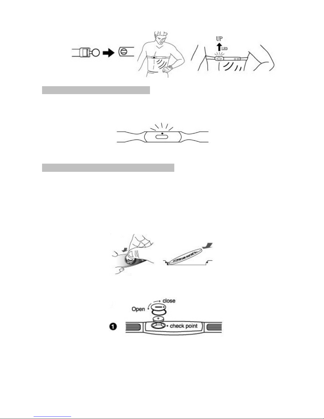
PUT ON HEART RATE TRANSMITTER
Install a CR2032 battery as back side illustrated. Position the heart rate
transmitter and adjust the elastic strap to fit your chest snugly as shown.
Heart Rate Transmitter
Elastic strap
CR2032 3V Lithium Battery
Battery Rubber Pad
Battery Cover
Page 18
18
TRANSMISSION LED INDICATOR
For checking operation of transmitter, the red LED indicator will flash indicating
the transmitter is in operation. Adjust the Transmitter position to keep the LED
indicator flashing consistently for accurate readings.
TRANSMITTER BATTERY INSTALLMENT
Slide the CR2032 battery at an angle and make sure during battery installation
that the battery is first pressed against the side contact (positive electrode) and
then pressed into the battery compartment.
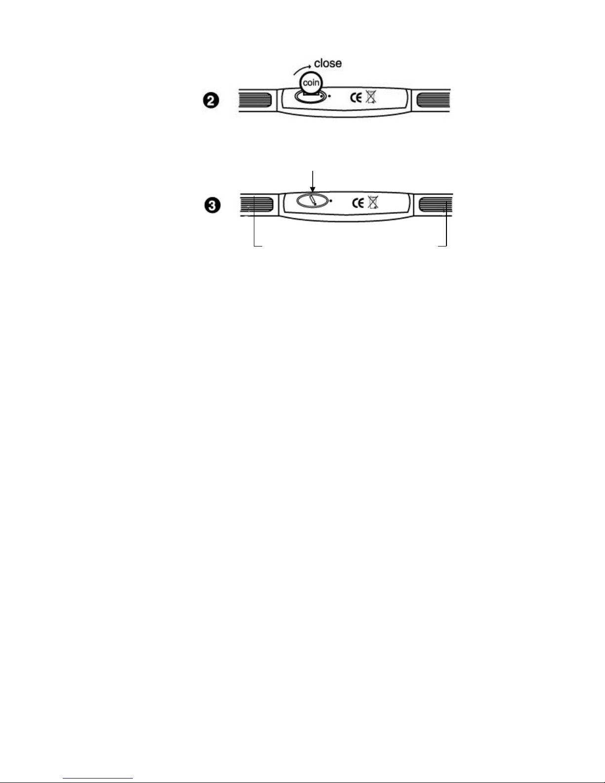
Place the battery rubber pad(O-ring) and battery cover properly into the case then close the
cover tightening it with a coin or similar object.
The rubber pad (O-ring) ensures water proof protection of the battery compartment.
IMPORTANT
Make sure to close the battery cover very tightly as below illustrated to prevent sweat and
moisture from spoiling the battery composition.
Page 19
19
NOTICE
Use water, ECG gel to other conductive liquids to moisten the conductive rubber skin
contact.
But do not use Vaseline or oils which may insulate the Transmitter making it unable
to detect the heart rate signals.
User Information related to the WEEE:
Decree n° 2005-829 of July 20, 2005 relating to the composition of electric and electronic
equipments and to the waste disposal resulted from these equipments
TITLE III
PROVISIONS RELATING TO THE COLLECTION OF HOUSEHOLD WASTE ELECTRIC AND
ELECTRONIC EQUIPMENTS
Article 12
Municipalities or their groupings, producers, distributors and coordinating organizations implement
the actions that they deem appropriate to inform users of household electric and electronic
equipments:
- of the obligation not to dispose the waste of electric and electronic equipment with unsorted
municipal waste; of the collection systems available to them;
Of the effects on the environment and human health from the presence of dangerous substances in
the electric and electronic equipments.
Correct position of battery cover
Conductive rubber
Apply water/conductive gel here
Page 20

GARLANDO SPA
Via Regione Piemonte, 32 - Zona Industriale D1
15068 - Pozzolo Formigaro (AL) - Italy
www.toorx.it - [email protected]
 Loading...