

Ed : 03/17 Rev : 00
INSTRUCTION
Thank you for choosing the RowerMachine. We
take great pride in producing this quality product and
hope it will provide many hours of quality exercise to
make you feel better,look better, and enjoy life to its
fullest.
It's a proven fact that a regular exercise program can
improve your physical and mental health. Too often,
our busy lifestyles limit our time and opportunity to
exercise. The RowerMachineprovides a convenient
and simple method to begin your assault on getting
your body in shape and achieving a happier and
healthier lifestyle.
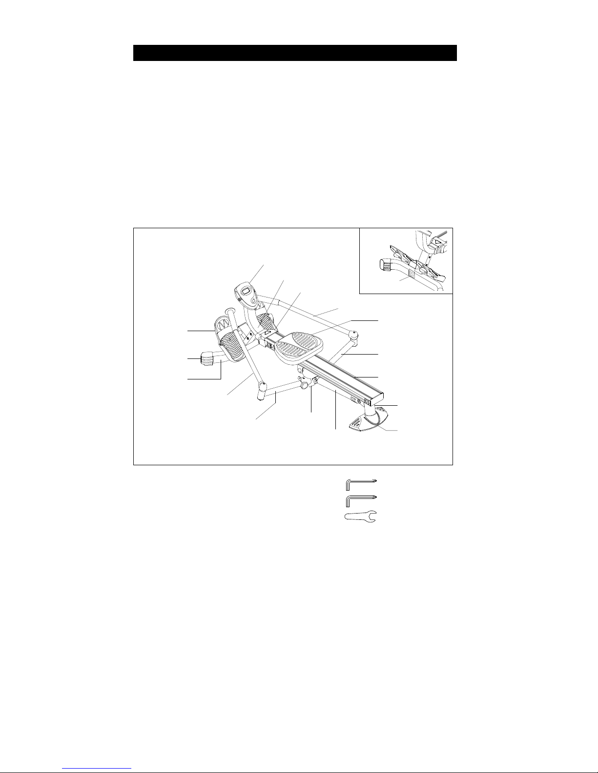
Before reading further, please review the drawing
below and familiarize yourself with the parts that
are labeled.
Read this manual carefully before using the
RowerMachine.
Meter
Front Support
Front Cover
Right Handlebar
Left
Stand Cap
Extension Arm
Front
Center Beam
Stabilizer
Left Handlebar
Pivot Connector
Shock
Stabilizer
Cap
THE FOLLOWING TOOLS ARE REQUIRED FOR ASSEMBLY : Allen Wrench (6mm)
Allen Wrench (
6mm)
Wrench (13mm)
Caution Label
Seat
Pedal Cap
Extension Arm
Rear Support
BEFORE YOU BEGIN
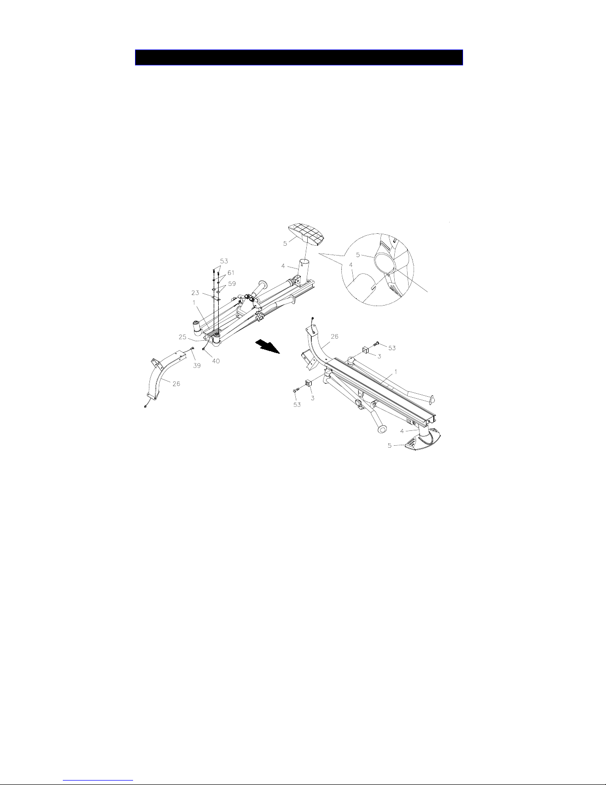
STEP 1
Lay the Main Frame Assembly on the floor as shown in the illustration. Now refer to the inset
drawing .Make sure the Key Rib in the STABILIZER CAP(5) aligns with the slot in the REAR
SUPPORT(4), then press the STABILIZER CAP(5) onto the REAR SUPPORT(4).
STEP 2
Connect the EXTENSION WIRE(39) to the SENSOR WIRE(40). Then insert the FRONT SUPPORT(26
)
into the SLEEVE(25) which in inside of the CENTER BEAM(1) and secure with the SUPPORT
PLATE(23), BUTTON HEAD BOLTS(M8x1.25x25mm)(53), LOCK WASHERS(M8)(61), and
WASHERS(M8)(59).
STEP 3
Turn the Main Frame Assembly to the normal upright position. Attach the SEAT STOPPERS(3) to both
Sides of the CENTER BEAM(1) with BUTTON HEAD BOLTS(M8x1.25*25mm)(53).
ASSEMBLY INSTRUCTIONS
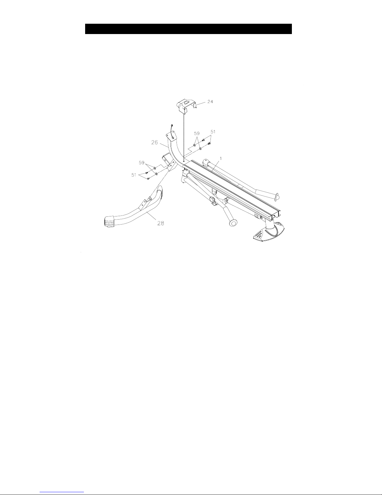
STEP
4
Insert the Bracket on FRONT STABILIZER(28) into the FRONT SUPPORT(26) and secure with
BUTTON HEAD BOLTS(M8x1.25x15mm)(51) and WASHERS(M8)(59).
STEP 5
Press the FRONT COVER(24) onto the FRONT SUPPORT(26).
ASSEMBLY INSTRUCTIONS
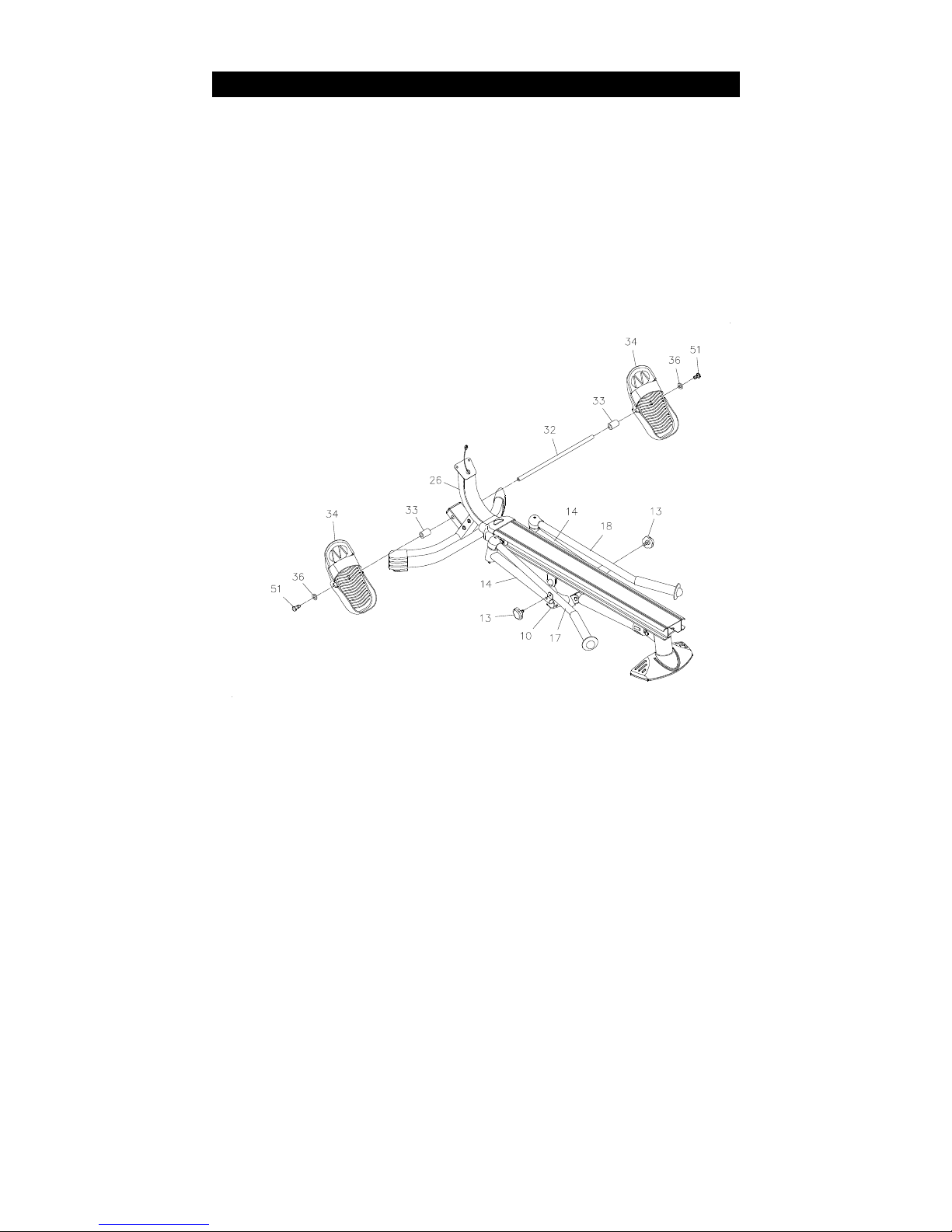
STEP 6
Insert the PEDAL SHAFT(32) through holes located on the FRONT SUPPORT(26). Slide a PEDAL
SPACER(33) and a PEDAL CAP(34) onto each end of the PEDAL SHAFT(32). Then secure the PEDAL
CAPS(34) with BUTTON HEAD BOLTS(M8x1.25x15mm)(51) and LARGE WASHERS(M8)(36) at both
ends of the PEDAL SHAFT(32).
NOTE: You need to use two Allen Wrenches to tighten the BUTTON HEAD BOLTS(M8x1.25x
15mm)(51)
at both ends of the PEDAL SHAFT(32) at the same time.
STEP 7
Remove the LOCKING KNOBS(13) from the PIVOT CONNECTOR(10).
ASSEMBLY INSTRUCTIONS

STEP 8
Unfold the HANDLEBARS(17, 18) and the EXTENSION ARMS(14) as shown in the illustration. Attach
the EXTENSION ARMS(14) to the PIVOT CONNECTOR(10) with the LOCKING KNOBS(13).
STEP 9
Install two AA batteries into the METER(37). See page 12 for detailed battery installation instructions.
Connect the EXTENSION WIRE(39) to the METER(37). Attach the METER(37) to the plate on the FRONT
SUPPORT(26) with ROUND HEAD SCREWS(M5x0.8x12mm)(49).
ASSEMBLY INSTRUCTIONS

STEP 10
Slide the SEAT ASSEMBLY(42, 43) into the CENTER BEAM(1). Attach the SEAT STOPPERS(3) to the
back end of the CENTER BEAM(1) with BUTTON HEAD BOLTS(M8x1.25x25mm)(53), WASHERS(M8
)
(59), and NYLOCK NUTS(M8x1.25)(38).
STEP 11
Press the CENTER BEAM CAP(2) into the back end of the CENTER BEAM(1)
.
ASSEMBLY INSTRUCTIONS

POWER
ON :
Seat movement or press the button.
POWER OFF : Automatic shut off after four minutes of inactivity.
MODE/RESET BUTTON:
Press to select display functions, include SCAN, TIME,
COUNT,TOTAL COUNT, and CALORIE. Press and hold
for four seconds to reset all functions to zero, except
TOTAL COUNT.
Functions:
SCAN: Automatically scans each function of TIME, COUNT, TOTAL COUNT, and CALORIE in
sequence with a change every six seconds.
TIME: Displays the elapsed time from 1 sec up to 99:59 minutes.
COUNT: Displays the total number of rows you have ta
ken from zero to 9999 rows.
TOTAL COUNT: Displays the total accumulated number of rows you have taken from zero to 9999 rows.
The total accumulated rows is retained when the meter is turned off.
CALORIE: Displays the calorie consumption from zero to 9999 cal. The calorie readout is an estimate
for an average user. It should be used only as a comparison between workouts on this unit.
NOTE: The TOTAL COUNT will be reset to zero after batteries are removed for battery replacement
or storage of the unit.
HOW TO INSTALL AND REPLACE BATTERIES:
1. Open the Battery Door on the back of the meter.
2. The meter operates with two AA batteries. Refer to the
illustration to install or replace the batteries.
NOTE:
1. Do not mix a new battery with an old battery.
2. Use the same type of battery. Do not mix an alkaline battery with
another type of battery.
3. Rechargeable batteries are not
recommended.
USING THE FITNESS METER
AA Batteries

LOAD ADJUSTMENT
The resistance of the shocks can be adjusted by twisting the
adjustment knob at the top of the shocks. There are settings from 1
to 12. Setting #1 will provide the lowest resistance. Setting #12 will
provide the highest resistance.
CAUTION
: The shocks get HOT after a few minutes of use.

1. To store the
Rower Machine ,
simply keep it in a clean dry place.
2. To avoid damage to the electronics meter, remove the batteries before storing the Rower Machine
for one year or more.
3. Grasp the Front and Rear Stabilizer to move the Rower Machine .
Do not use the Seat to move the
Rower Machine . The Seat will move and the Seat Carriage may pinch your hand or fingers
A.
Folding the Rower Machine
Follow the following process to fold The Rower
Machine as illustrated for easy storage.
A.
Slide the SEAT(42) to the front end of the
CENTER
BEAM(1). Remove the LOCKING KNOBS(13) from
the PIVOT CONNECTOR(10).
B. Swing the LEFT and
RIGHT HANDLEBARS(17, 18)
Backward. Then fold the EXTENSION ARMS(14) to
front.
B.
C. Lock the handlebars in the folded position by
screwing the LOCKING KNOBS(13) onto the PIVOT
CONNECTOR(10). Now, you can store the Rower
Machine in the place you want.
D. Refer to illustration D. You can stand the Rower
Machine on end for storage.
D.
C.
STORAGE

PRODUCT PARTS DRAWING

PART# PART NAME QTY
1 Center Beam 1
2 Center Beam Cap 1
3 Seat Stopper 4
4 Rear Support 1
5 Stabilizer Cap 1
6 Stabilizer Pad 1
7 Threaded Support Plate 3
8 Handlebar Support 1
9 Sensor Support Plate 1
10 Pivot Connector 1
11 Pivot Bushing 2
12 Bumper Knob 2
13 Locking Knob 2
14 Extension Arm 2
15 Extension Arm Bushing 4
16 Large Washer (3/8”) 2
17 Left Handlebar 1
18 Right Handlebar 1
19 Securing Cap 2
20 Foam Grip 2
21 Handlebar Cap 2
22 Shock 1
23 Support Plate 1
24 Front Cover 1
25 Sleeve 1
26 Front Support 1
27 Shock Caution 1
28 Front Stabilizer 1
29 Left Stand Cap 1
30 Right Stand Cap 1
31 Nylock Nut (3/8” - 16) 3
32 Pedal Shaft 1
33 Pedal Spacer 2
34 Pedal Cap 2
35 Pedal Strap 2
36 Large Washer (M8) 2
37 Meter 1
38 Nylock Nut (M8 x 1.25) 10
39 Extension Wire 1
40 Sensor Wire 1
41 Magnet 1
42 Seat 1
43 Seat Carriage 1
44 Roller 4
45 Oval Plug (40 x 80mm) 1
46 Nut Cap (3/8”) 2
47 Screw, Round Head (M3.5 x 12mm) 2

PART# PART NAME QTY
48 Screw, Round Head (M3.5 x 15mm) 7
49 Screw, Round Head (M5 x 0.8 x 12mm) 4
50 Bolt, Round Head (M6 x 1 x 14mm) 4
51 Bolt, Button Head (M8 x 1.25 x 15mm) 6
52 Bolt, Button Head (M8 x 1.25 x 20mm) 8
53 Bolt, Button Head (M8 x 1.25 x 25mm) 6
54 Bolt, Button Head (M8 x 1.25 x 55mm) 2
55 Bolt, Hex Head (M8 x 1.25 x 32mm) 4
56 Bolt, Hex Head (M8 x 1.25 x 41mm) 2
57 Bolt, Hex Head (3/8” - 16 x 4 7/8”) 1
58 Washer (M6) 4
59 Washer (M8) 28
60 Washer (3/8”) 2
61 Lock Washer (M8) 14
62 Caution Label 1
63 Allen Wrench (6mm) 2
64 Wrench (13mm) 1
65 Owner’s Manual 1

GARLANDO SPA
Via Regione Piemonte, 32 - Zona Industriale D1
15068 - Pozzolo Formigaro (AL) - Italy
www.toorx.it - info@toorx.it
 Loading...