

TOORX MSX-70 Instruction Manual
INSTRUCTION
Rev : 0000
Ed : 02/17
Contents
Care and Maintenance
Free area and training area
Resistance chart
31
Exploded Parts List
32-
34
Guarantee
35
Components - Parts
Components – Fixings
Assembly Instructions
Home Gym Exercise
Guide Exercising
Information
Before starting to exercise 25
Muscle chart 26
Warming up and cooling down
Exercises
3-4
5
6-21
22-24
25-28
27-28
29
30
1
MUST r
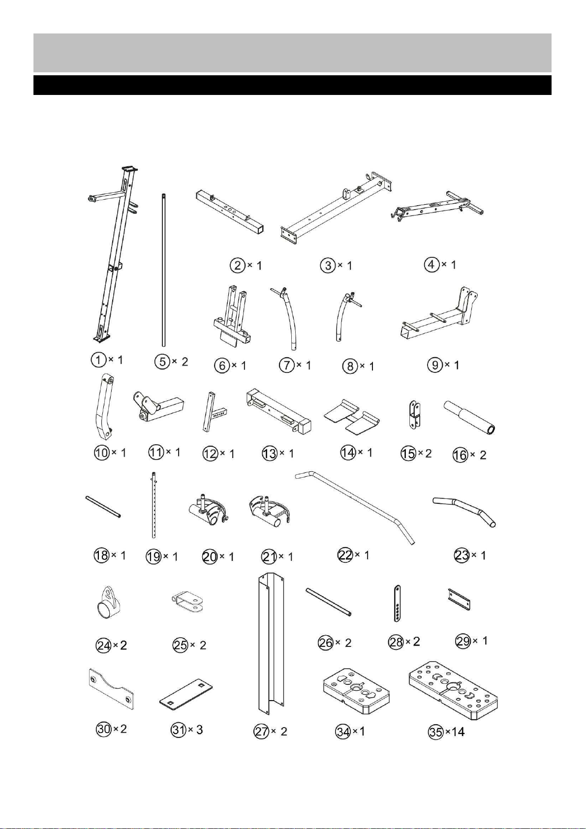
Components
- Parts
personal injury or property damage sustained by or
Please check you have all parts listed below
Note: Some of the smaller components may be pre-fitted to larger components. Please check carefully
before contacting Argos regarding any missing components.
ead all instructions before using any fitness equipment. Argos assumes no responsibility for
3
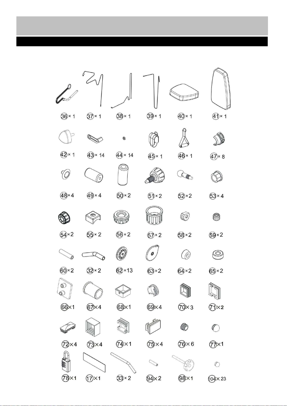
Components
- Parts
Please check you have all parts listed below
Note: Some of the smaller components may be pre-fitted to larger components. Please check carefully
before contacting Argos regarding any missing components.
4
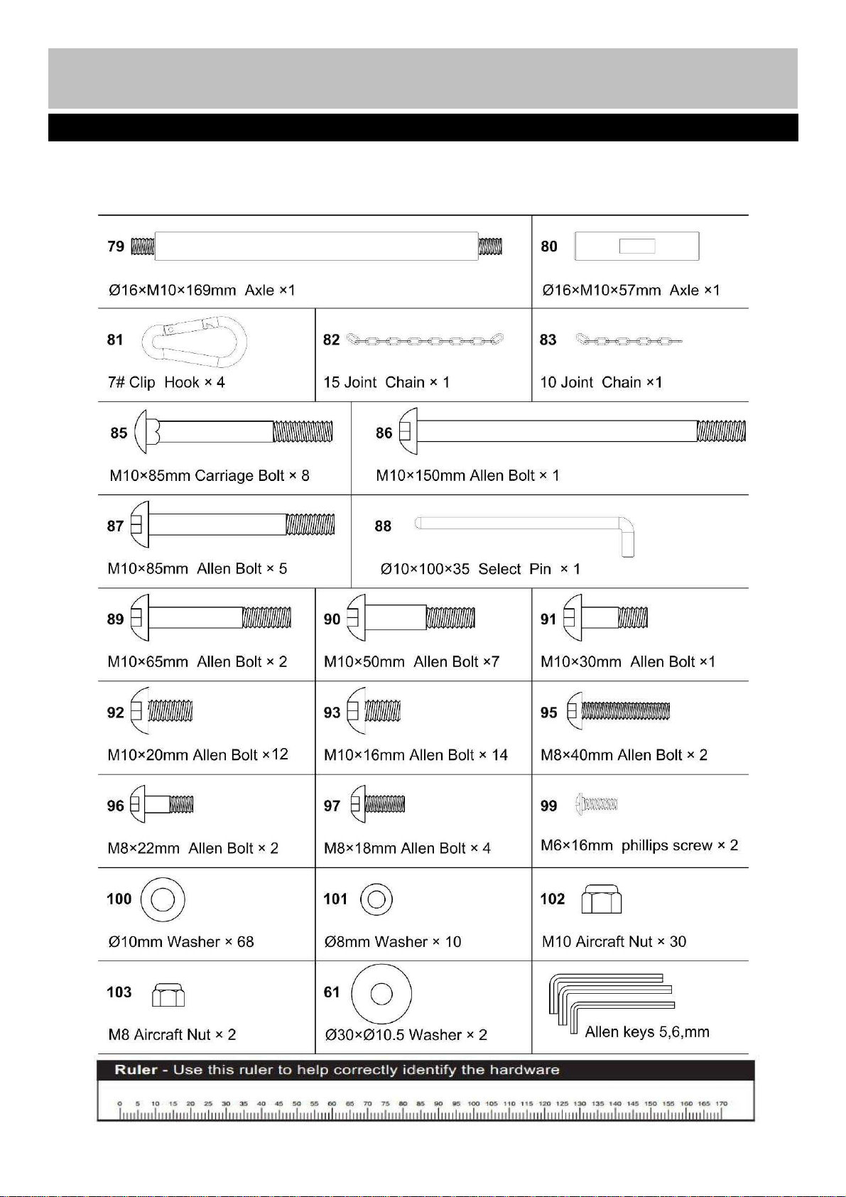
Components - Fixings
Please check you have all fixings listed below
Note: Some of the smaller components may be pre-fitted to the larger components. Please check carefully
before contacting Argos regarding any missing components. Please prepare an adjustable spanner by
yourself when you are intend to assemble this machine.
5

Assembly instructions
Step 1
(A).Insert the 2pcs guide rods (5)
into the holes of the rear
stabilizer (2) separately . and
Secure them with 2 pcs
Ø10mm Washers (100) and 2
pcs M10 x 20mm Allen Bolts
(92) . Slide the 2pcs rubber
bumpers (65) along the guide
rods from the top to the
bottom.
(B).Attach the main base frame (3)
to the rear stabilizer(2), Secure
them with 2pcs M10×85
carriage bolts(85), one pc
bracket(29), 2pcs Ø10
washers(100) and 2 pcs M10
Aircraft nuts(102).
(C).Attach the front stabilizer(13)
to the main base frame(3),
Secure them with one pc
bracket(31), 2pcs M10×85
carriage bolts(85), 2pcsØ10
washer(100) and 2 pcs M10
Aircraft nut(102).
.
6
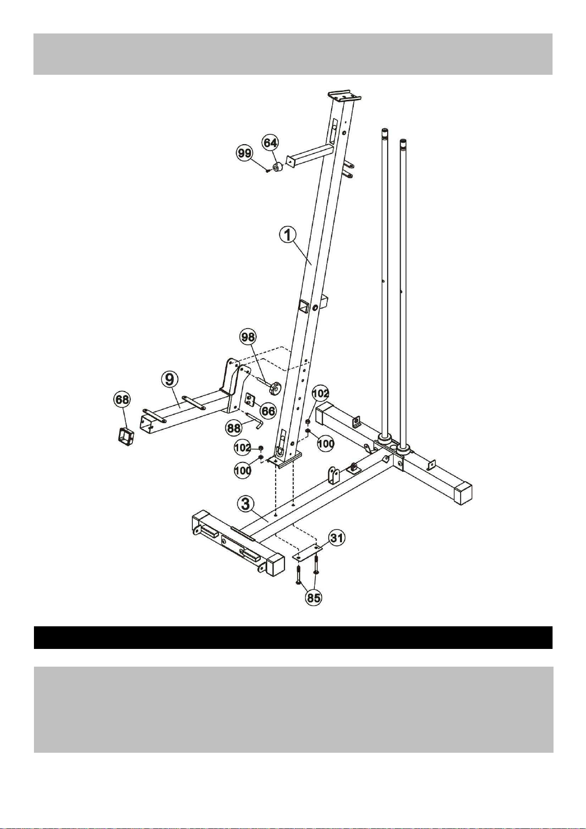
Assembly instructions
Step 2
7
(A) Attach the front vertical frame (1) onto the main base frame(3) , carefully align the holes and secure
them with 2 pcs M10×85 carriage bolts(85), one pc bracket (31),2pcs 2pcsØ10 washer(100) and 2
pcs M10 Aircraft nut(102).
(B) Attach the seat pad support(9) to the front vertical frame(1) and secure them with M10*93 Lock
knob(98) and one pc select pin(88)

Assembly instructions
Step 3
(A). Slide the 14pcs weight
plate(35) along the guide rods (5)
from the top to the bottom.insert
the selector rod (19) into the hole
of weight plates.and then place
the weight selector(34) onto the
selector rod (19)
(B) Attach the foot plate (14) to the
front stabilizer(13), Secure them
with 2pcs M10*20 Allen bolt(92),
2pcsØ10 washer(100) and one
pc Foot plate tube(18).
.
Make sure that all the grooves
face downwards and front.
8
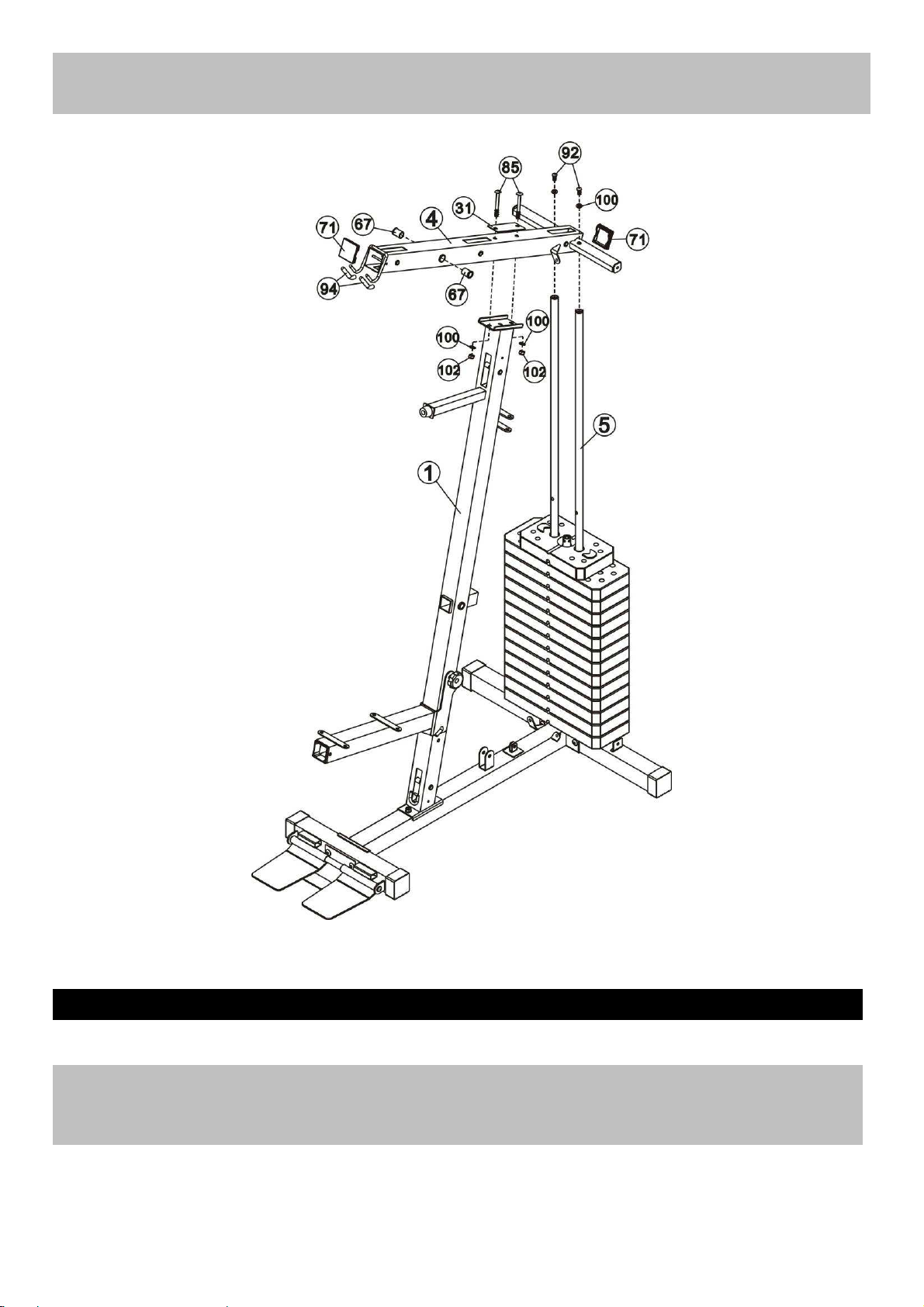
Assembly instructions
Step 4
Place the upper frame (4) onto the front vertical frame (1) and 2 pcs guide rods (5), Carefully align the
holes and secure them with 2pcs M10*20 Allen bolt (92), 2pcs Ø10 washers (100). 2pcs M10*85
Crriage bolts(85), one pc bracket(31), 2pcsØ10 washers (100) and 2pcs M10 aircraft nuts(102).
9
 Loading...