

Page 1

INSTRUCTION
Rev : 0000
Ed : 02/17
Page 2
11
Contents
Safety Information
Components - Parts
Components – Fixings
Assembly Instructions
Resistance chart
Home Gym Exercise Guide
Home Gym Exercise Guide
Exercising Information
Before starting to exercise 29
Muscle chart 30
Warming up and cooling down
Exercises
3-5
6-7
8-24
25
26-28
29-32
31-32
2
Care and Maintenance 33
Free area and training area 34
Exploded Parts List 35-38
Guarantee 38
1
Page 3
MUST read all instructions before using any fitness equipment. Argos assumes no responsibility for
personal injury or property damage sustained by or through the use of this product.
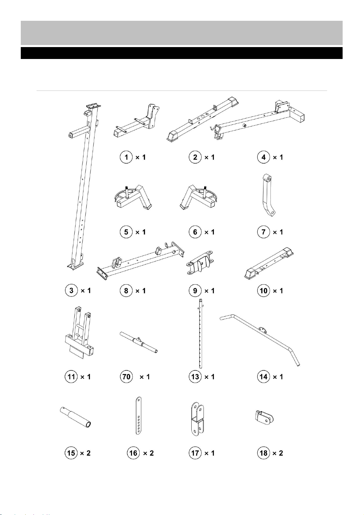
Note: Some of the smaller components may be pre-fitted to larger components. Please check carefully
before contacting Argos regarding any missing components.
Components - Parts
Please check you have all parts listed below
3
Page 4
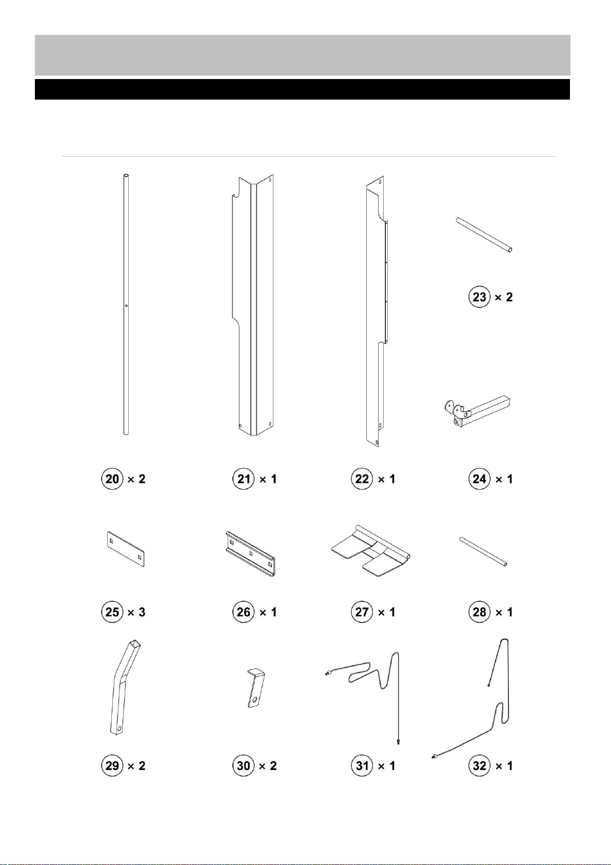
Note: Some of the smaller components may be pre-fitted to larger components. Please check carefully
before contacting us regarding any missing components.
Components - Parts
Please check you have all parts listed below
4
Page 5
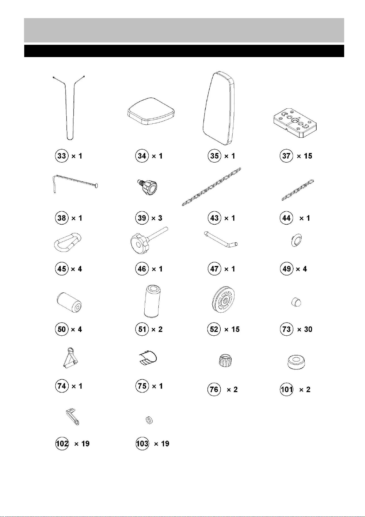
Components - Parts
Please check you have all parts listed below
5
Page 6
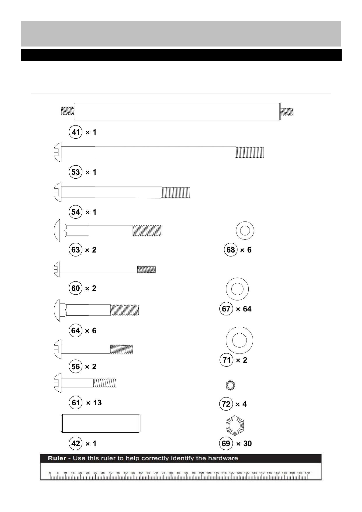
Note: Some of the smaller components may be pre-fitted to the larger components. Please check carefully
before contacting us regarding any missing components. Please prepare an adjustable spanner by
yourself when you are intend to assemble this machine.
Components - Fixings
Please check you have all fixings listed below
6
Page 7
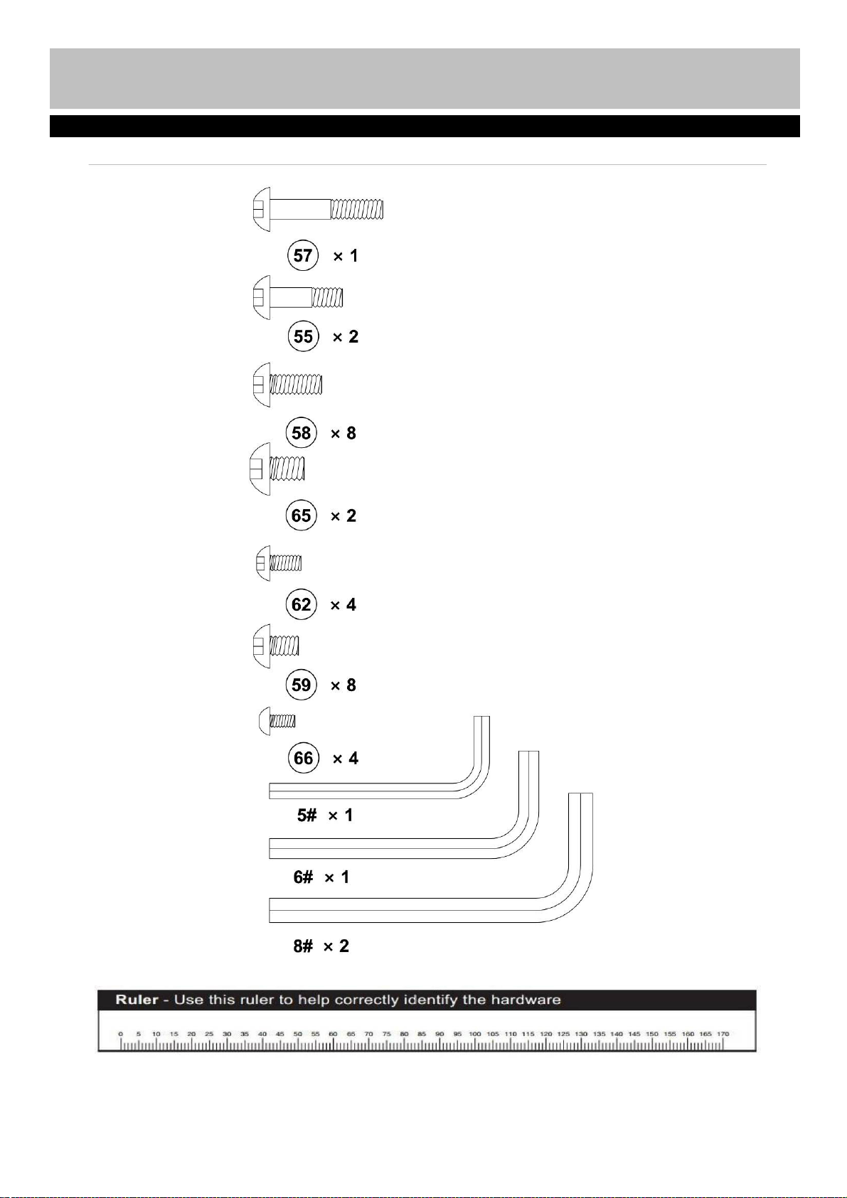
Components - Fixings
Please check you have all fixings listed below
7
Page 8
Assembly instructions
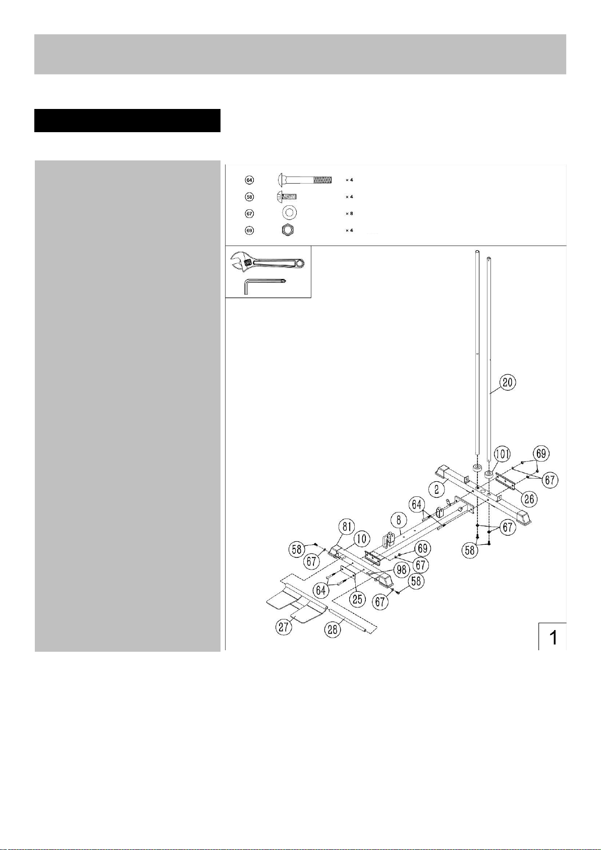
Step 1
(A) Insert the 2pcs guide rods (20)
into the holes of the rear
stabilizer (2) separately . and
Secure them with 2 pcs Ø10mm
Washers (67) and 2 pcs M10 x
25mm Allen Bolts (58) . Slide the
2pcs rubber bumpers (101) along
the 2 pcs guide rods from the top
to the bottom.
(B) Attach the main base frame (8) to
the rear stabilizer(2), Secure them
with 2pcs M10×70 carriage
bolts(64), one pc bracket(26),
2pcs Ø10 washers(67) and 2 pcs
M10 Aircraft nuts(69).
(C) Attach the front stabilizer(10) to
the main base frame(8), Secure
them with one pc bracket(25),
2pcs M10×70 carriage bolts(64),
2pcsØ10 washers(67) and 2 pcs
M10 aircraft nuts(69).
(D) Attach the foot palte (27) to the
front stabilizer(10), Fix them with
one pc foot plate tube(28), two
pcs M10*25 Allen bolt(58),
2pcsØ10 washer(67)
.
8
Page 9
Assembly instructions
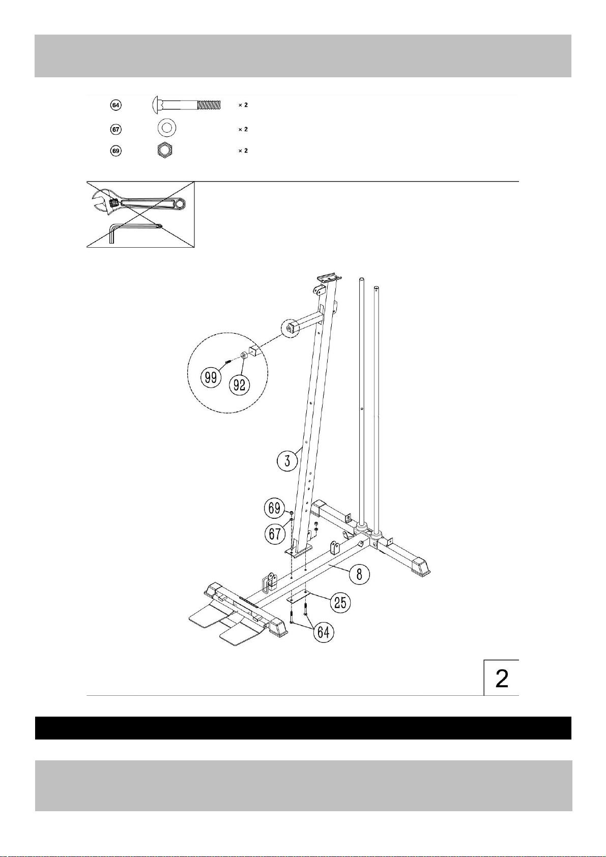
Step 2
Attach the front vertical frame (3) onto the main base frame(8) , carefully align the holes and secure them
with 2 pcs M10×70 carriage bolts(64), one pc bracket (25),2pcs 2pcs Ø10 washers (67) and 2 pcs M10
Aircraft nuts (69).
9
Page 10
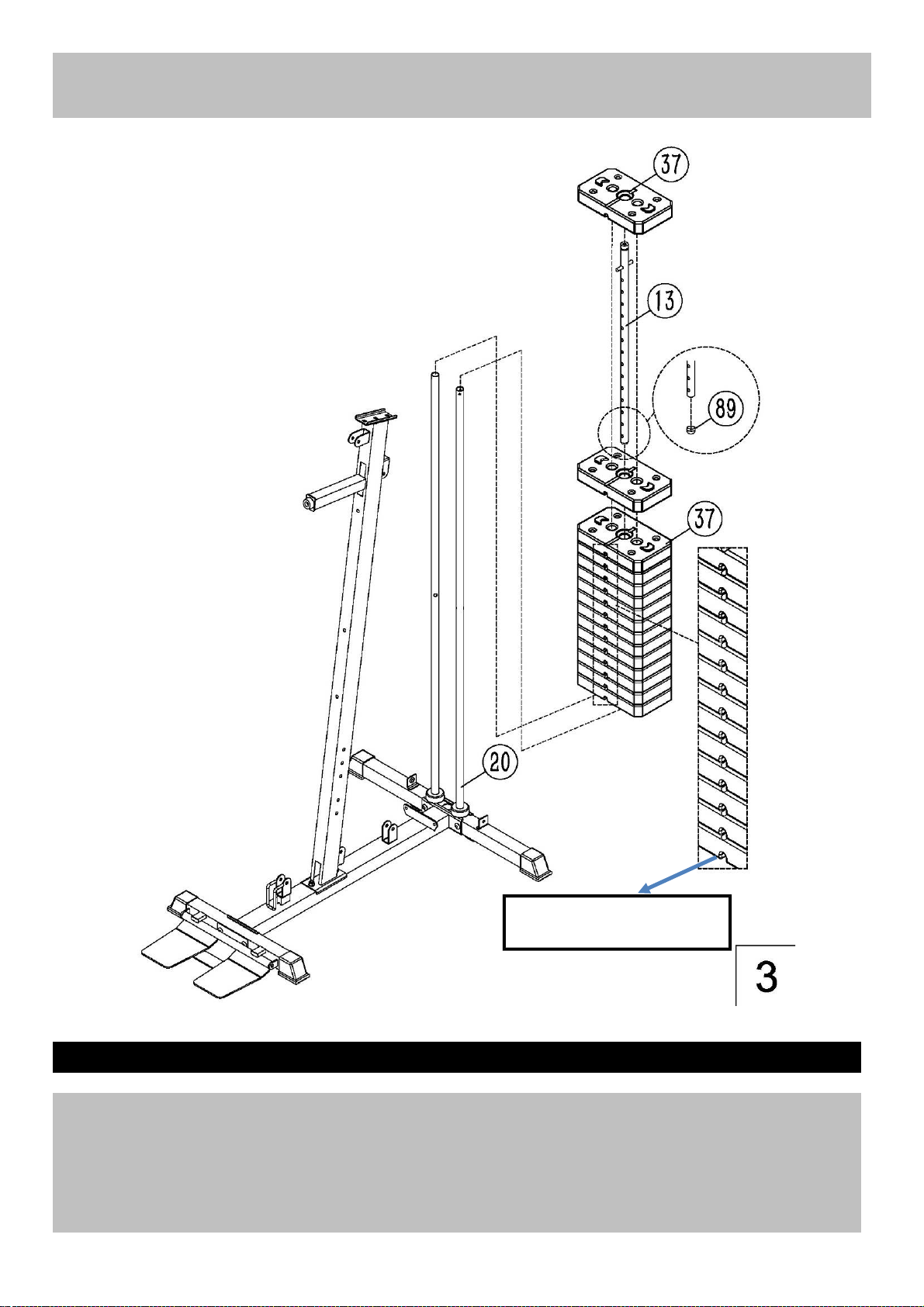
Assembly instructions
Make sure that all the grooves
face front and backwards.
Step 3
(A)Slide the 14pcs weight plate(37) along the guide rods (20) from the top to the bottom.insert the
selector rod (13) into the hole of weight plates. and then place the last weight plate onto the selector
rod (19)
Make sure that all the grooves face front and backwards.
(B) Insert the selector pin (38) into the hole and select the desired weight when exercising.
.
10
Page 11
Assembly instructions
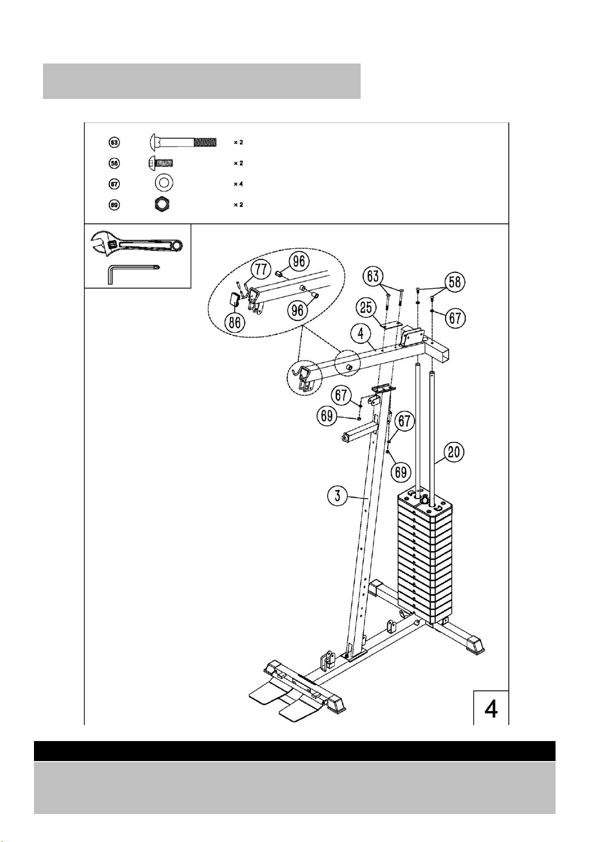
Step 4
Place the upper frame (4) onto the front vertical frame (3) and 2 pcs guide rods, Carefully align the holes
and secure them with 2pcs M10*25 Allen bolt (58), 2pcs Ø10 washers (67). 2pcs M10*90 Crriage
bolts(63), one pc bracket(25), 2pcsØ10 washers (67) and 2pcs M10 aircraft nuts(69).
11
Page 12
Assembly instructions
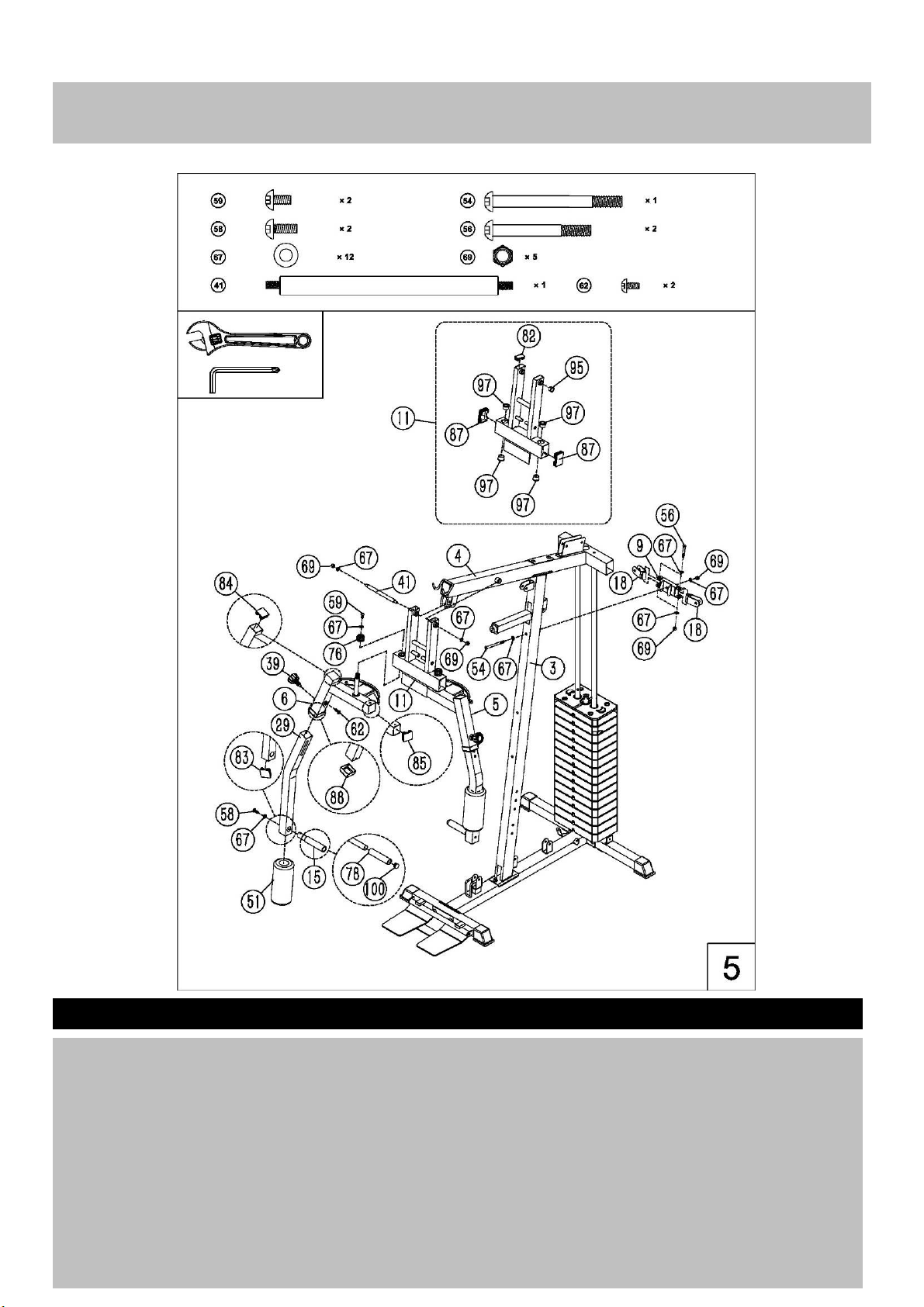
Step 5
(A). Attach the front press base (11) to the upper frame (4), Secure them with one pc Ø16*M10*206
axle(41), 2pcs Ø10 washers (67) and 2pcs M10 aircraft nuts (69).
(B) Attach the upper right butterfly frame(6) through the hole of the front press base(11) as the diagram
shows and secure them with M18 Lock ring(76), 1 pc Ø10 washer (67), 1pc M10 X16 Allen bolt
(59).Insert the lower right butterfly frame(29) into the opening of upper right butterfly frame(6) and adjust
it with one pc Lock knob (39) and one pc M10*18 Allen bolt (62).Push one pc foam roll(51) from the
bottom of the lower right butterfly frame and then secure the butterfly handle (15) with 1 pc Ø10 washer
(67), 1pc M10 X25 Allen bolt (58). Install the total left butterfly frame with the same way.
(C) Fix the swivel pulley bracket support (9) with one pc M10*110 Allen bolt (54), 2pcs Ø 10 washers(67)
and one pc M10 aircraft nut (69).Install the right and left swivel pulley bracket(18) with 2 pcs M10X65
Allen bolt (56), 4pcs Ø 10 washers(67) and 2 pcs M10 aircraft nuts (69).
Page 13
Assembly instructions
12
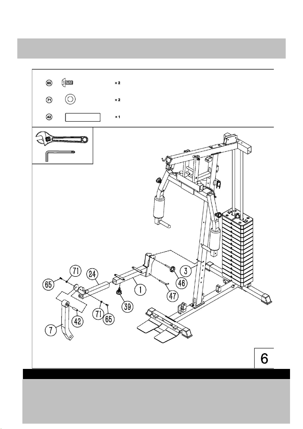
Step 6
(A) Attach the sest pad support (1) to the front vertical frame(3) with one pc L shape lock pin(47) and one
pc M10X85 Lock knob(46).
(B) Insert the leg developer holder (24) into the front opening of seat pad support (1).You would select the
desired position with Lock knob (39).
(C) Attach the leg developer (7) to the bracket as the diagram shows, Secure them with one pc
Ø16*M10*57 axle (42),2 pcs M12*20 Allen bolt(65) and 2pcs Ø12 washers (71) .
Page 14
Assembly instructions
14
Page 15

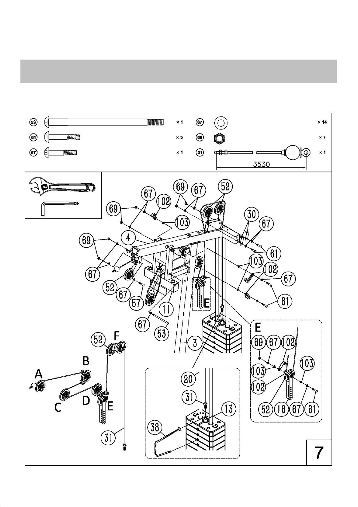
Step 7
(A) Attach the upper cable (31) through the first bracket and make sure that the ball stopper should be
underneath the upper frame(4). Place one pc pulley (52) below the cable and secure the pulley with
one pc M10*45 allen bolt (57) , 2 pcs Ø 10 washers (67) and one pc M10 aircraft nut (69).
(B) Draw the cable backwards and place one pc pulley as the diagram shows, secure the pulley with 2 pcs
cable retainers(102) , 2pcs cable retainer bushings(103)with one pc M10*50 allen bolt (61) , 2 pcs Ø 10
washers (67) and one pc M10 aircraft nut (69).
(C) Draw the cable and place one pc pulley as the diagram shows ,Seucre them with one pc M10*180
allen bolt(53),2 pcs Ø10 washers (67), and one pc M10 aircraft nut (69).
(D) Draw the cable around the pulley and backwards and go through the opening of front vertical frame,
secure the pulley,2 pcs cable retainer(102) , 2pcs cable retainer bushing(103) with one pc M10*50
allen bolt (61) , 2 pcs Ø 10 washers (67) and one pc M10 aircraft nut (69).
(E) Draw the cable downwards and place one pc pulley onto the cable, secure the pulley with 2pcs double
floating pulley brackets (16),2 pcs cable retainers(102), 2pcs cable retainer bushings (103) with one pc
M10*50 allen bolt (61) , 2 pcs Ø 10 washers (67) and one pc M10 aircraft nut (69).
(F) Draw the cable around the pulley and upwards and go through the last opening of the upper frame, Fix
two pcs pulley as the diagram shows with 2pcs M10X50 Allen bolt(61), 2 pcs cable retainers(30), 4 pcs
Ø 10 washers (67) and 2 pcs M10 aircraft nuts (69).Draw the cable onto the 2pcs pulleys and then go
downwards through the central hole .
(G) Insert the selector pin (38) into the hole to select the desired weight when exercising .Place the ring of
the lock pin through the top of the select rod.
(H) Draw the cable downards ,Attach the end bolt to the top of selector rod, Thread at least 5 laps to
ensure the safety.
15
Page 16
Assembly instructions
16
14
Page 17

Assembly instructions
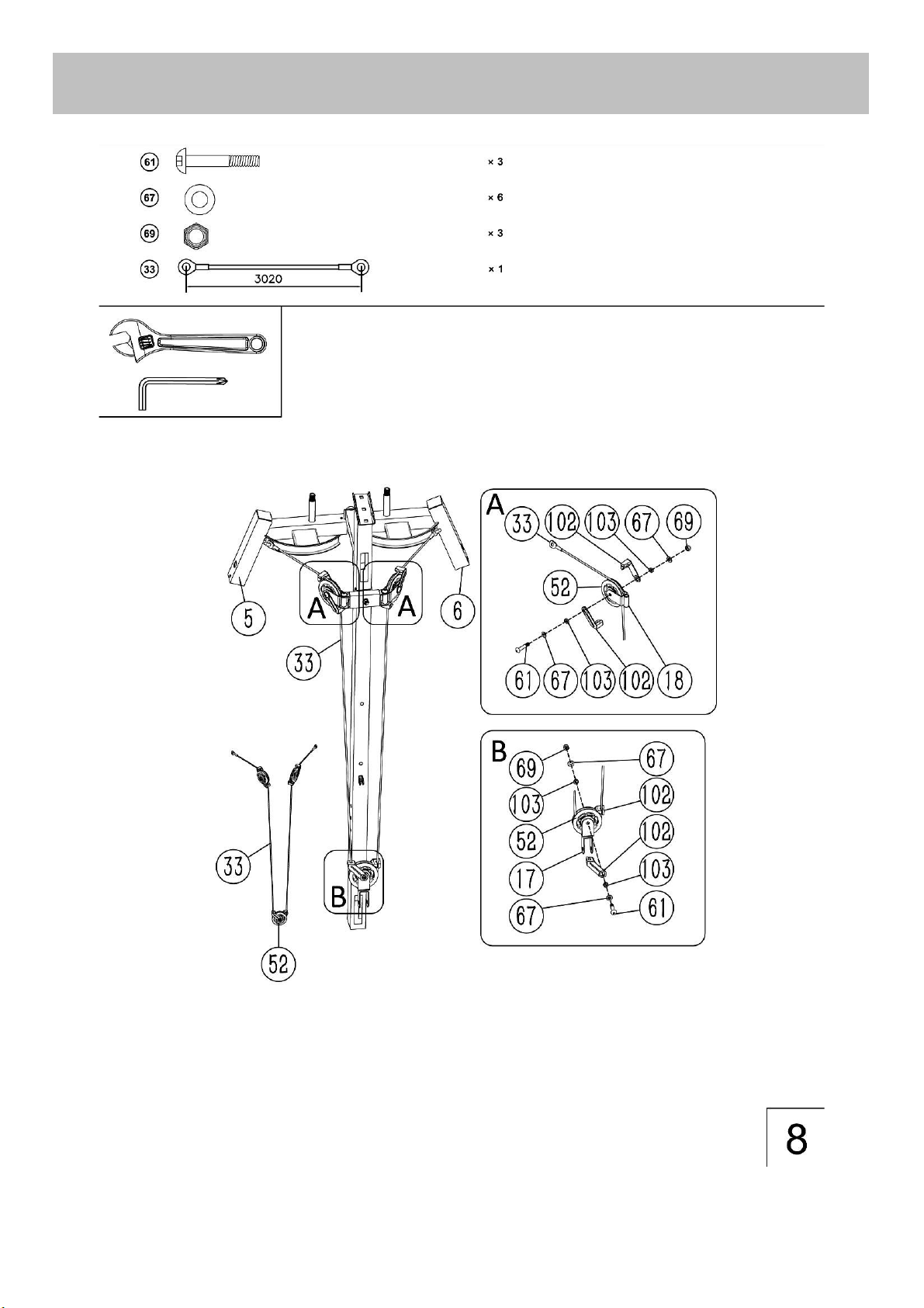
Step 8
(A). Attach one end of the butterfly cable (33) to the post of the upper right butterfly frame (6), Draw the
cable backwards and place one pc pulley below the cable. secure the pulley,2 pcs cable retainer(102) ,
2pcs cable retainer bushing(103) with the swivel pulley bracket (18) together with one pc M10*50 allen
bolt (61) , 2 pcs Ø 10 washers (67) and one pc M10 aircraft nut (69).
(B) Draw the cable downwards and place one pc pulley onto the cable.Secure the pulley,2 pcs cable
retainer(102) and angled floating pulley bracket(17) together with the same way in A.
(C) Draw the cable upwards and repeat the procedure B and A to fix another end of cable to the post of
upper left butterfly frame (5).
17
Page 18
Assembly instructions
E
A
F
C
B
D
18
Page 19

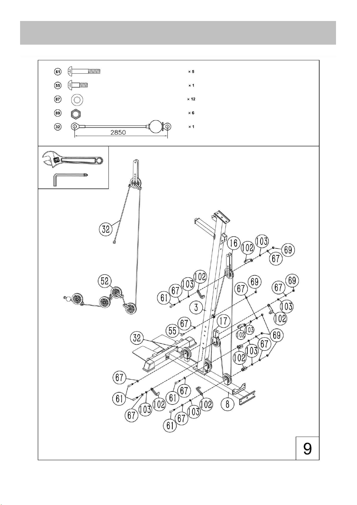
Step 9
(A) Draw the lower cable (32) through the first bracket,make sure that the ball stopper should be in front of
the bracket. Place one pc pulley onto the lower cable, Secure the pulley , one pc cable retainer(102) ,
one pc cable retainer bushing(103) with one pc M10*50 allen bolt(61), 2 pcs Ø10 washers (67) and
one pc M10 aircraft nut(69) .
(B) Draw the cable backwards and go through the opening of the front vertical frame,Place one pc pulley
onto the cable and secure the pulley with the same method in A.
(C) Draw the cable around the pulley and upwards and place one pc pulley below the cable. Secure the
cable , 2 pcs cable retainer(102) , 2 pcs cable retainer bushing(103) with the same way in A.
(D) Draw the cable downwards and place one pc pulley onto the cable, Secure the pulley with the same
way in C.
(E) Draw the cable upwards and place one pc pulley below the cable.Secure the pulley with the doubel
floating pulley bracket with the same way in C.
(F) Draw the cable dowmwards and fix the end of the cable as the diagram shows with one pc M10*28
Allen bolt (55), 2 pcs Ø10 washers (67) and M10 aircraft nut(69).
Page 20

Assembly instructions
19
Page 21

Step 10
(A) Attach the backrest pad (35) to front vertical frame (3) , Carefully align the holes and secure them with
2 pcs M8*85 allen bolt(60) and 2 pcs Ø8 washers (68) .
(B) Place the seat pad (34) onto the seat pad support (1), Sucure them with 4pcs Ø8 washers(68) and
4pcs M8*18 allen bolt (62).
(C) Insert the 2 pcs foam roll tubes (23) into the holes halfway as the diagram shows, and then push the
4pcs foam rolls(50) from both ends seperately, and then push the foam roll end cap (49).
Page 22
Assembly instructions
20
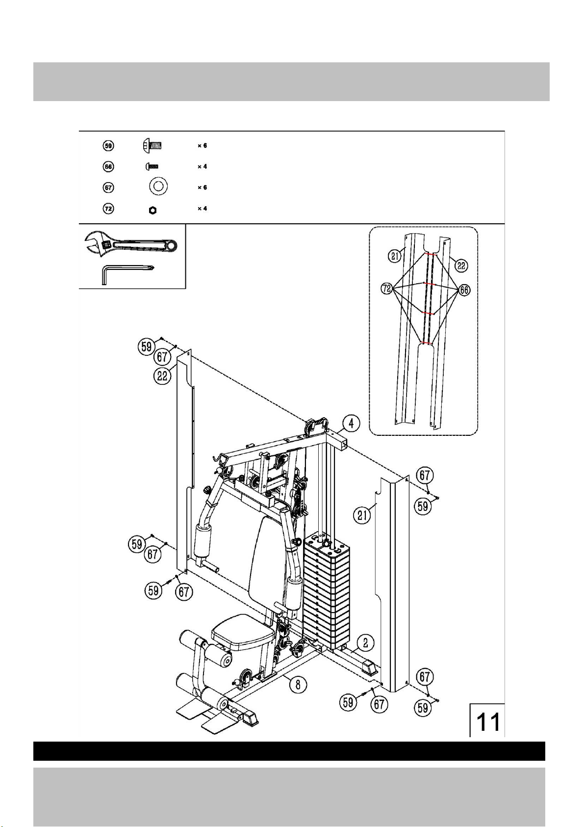
Step 11
(A) Attach the 2pcs left &right weight stack covers (21,22) onto the rear stabilizer separately and secure
them with 6pcs M10X16 Allen bolt (59) , 6 pcs Ø10 washer(67) .
(B) Connect the left and right weight stack cover together with 4pcs M5*10 Allen bolts(66)and 4 pcs M5
aircraft nuts(72) as the diagram shows.
Page 23
Assembly instructions
21
Page 24
Step 12
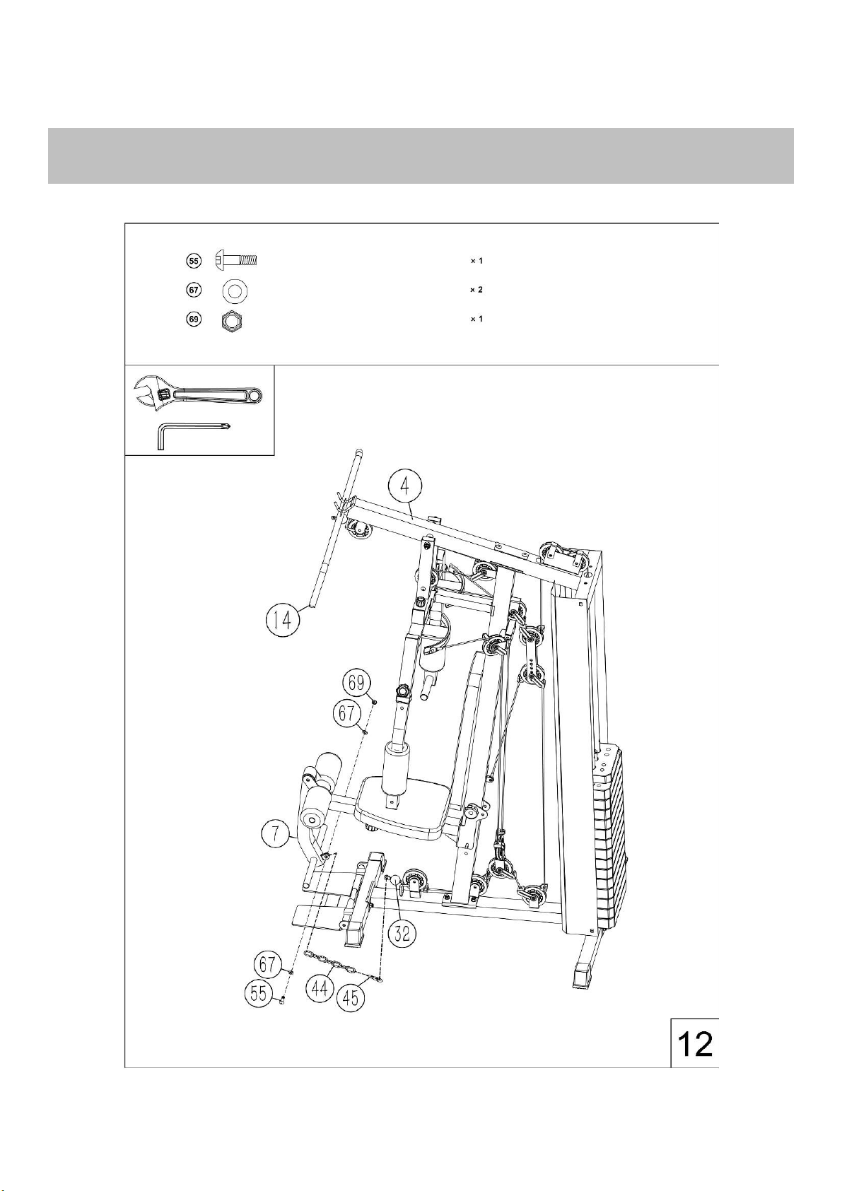
Connect the leg developer (7#) to the end of the lower cable with 1pcs gourd hooks(45) ,one pc 8-joint
chain(44),one pc M10*28 Allen bolt, 2pcs Ø10 washers(67) and one pc M10 Aircraft nut(69)
Assembly instructions
22
Step 13
Page 25
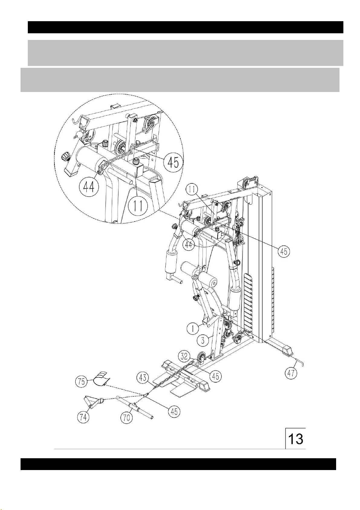
Fold the seat pad support as the diagram shows, you must fix the leg developer them as the diagram
shows with 2pcs gourd hook(45) and one pc 8-joint chain(44) for safety ,Connect the shiver bar (23) or
single strap(43) or angle strap(42) to the lower cable to do the desired exercise
23
Assembly instructions
Step 14
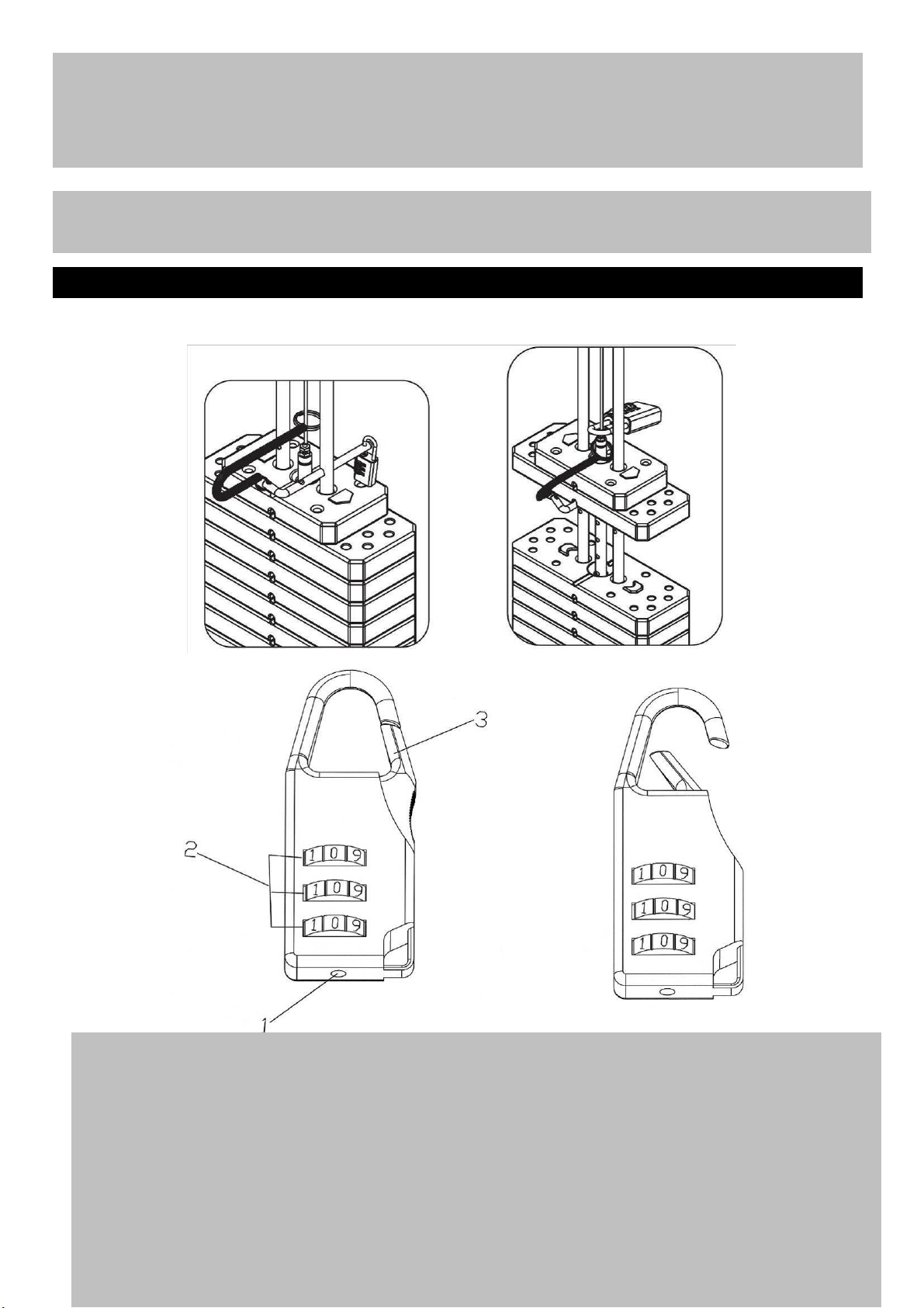
The Lock is set at the manufacturer to the open at 0-0-0 (all zeros are positioned in the middle). It
is recommended to change the combination to ensure safety.
Please follow the below steps to change the combination:
1. Push and hold the combination adjustment button (#1) as indicated below, while holding
down the adjustment button, turn the numerical dial (#2) to set the desired combination in
the middle. Release the button (#1). Set the two other numerical dials the same way. This
only needs to be done once.
2. To lock, turn the dials so the Lock shows random numbers.
3. To unlock, turn the dials to the combination setup in step one, press the shackle (#3) to
open.
Page 26
Resistance chart
24
Page 27

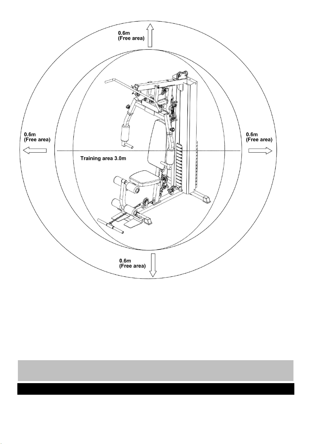
The free area should be no less than 0.6m greater than the training area in the directions from which the
equipment is accessed. The free area must also include the area for emergency dismount. Where
equipment is positioned adjacent to each other the value of the free area may be shared.
33
Free area and training area
Page 28
Part Description Qty. Part Description Qty.
34
Exploded Parts List
Page 29

1 Seat pad support 1 22 Right weight cover 1
2 Rear stabilizer 1 23 Foam roll tube 1
3 Front vertical frame 1 24 Leg developer holder 2
4 Upper frame 1 25 140X50 bracket 3
5 Upper left butterfly frame 1 26 bracket 1
6 upper right butterfly frame 1 27 Foot plate 1
7 Leg developer 1 28 Foot plate tube 1
8 Main base frame 1 29 Right & left lower butterfly frame 2
9 Swivel Pulley bracket support 1 30 Cable retainer 1
10 Front stabilizer 1 31 Upper cable 1
11 Front press frame 1 32 Lower cable 1
12 Pull bar tube 2 33 Butterfly cable 1
13 Selector rod 1 34 Seat pad 1
14 Lat bar 1 35 Backrest pad 1
15 Butterfly handle 2 36 0
16 Pulley bracket support 1 37 10 LBS Weight plate 14
17 angled floating pulley bracket 1 38 Selector pin 1
18 Swivel pulley bracket 2 39 Lock knob 1
19 Handle bracket 1 40 Combination lock 1
20 Guide rod 2 41 Ø16X206*M10 axle 1
21 Left weight cover 1 42 Ø16X57*M12 axle 1
43 15 Joint chain 1 66 M5*10 Philips screw 4
Exploded Parts List
35
Page 30

44 8 Joint chain 1 67 Ø10 washer 64
45 7# gourd hook 4 68 Ø8 washer 6
46 M10*85 lock knob 1 69 M10 Aircraft nut 30
47 L shape pin 1 70 Pull bar 1
48
口
50 rubber bumper 1 71 Ø12 washer 2
49 Foam roll end cap 4 72 M5 Aircraft nut 4
50 Foam roll 4 73 M10 Aircraft nut cover 30
51 Butterfly foam roll 2 74 Single strap 1
52 pulley 15 75 Angle strap 1
53 M10*180 Allen bolt 1 76 M8*15 Lock ring 2
54 M10*110 Allen bolt 1 77 Handle grip 2
55 M10*28 Allen bolt 2 78 Ø25*130 handle grip 2
56 M10*65 Allen bolt 2 79 Ø25*170 handle grip 2
57 M10*45 Allen bolt 1 80 Ø25*500 handle grip 2
58 M10*25 Allen bolt 8 81
口
50 foot 4
59 M10*16 Allen bolt 8 82 50*20*1.5 End cap 2
60 M10*85 Allen bolt 2 83
口
45*1.5 End cap 4
61 M10*50 Allen bolt 13 84
口 50*1.5 End cap
3
62 M10*18 Allen bolt 6 85
口 50*2 End cap
2
63 M10*110 Carriage bolt 2 86 50*70*1.5 End cap 1
64 M10*70 Carriage bolt 6 87 50*70*2 End cap 2
65 M12*20 Allen bolt 2 88
口 50*口 45 sleeve
3
89 Ø25 end cap 1
90 Ø38* Ø27*26 bushing 2
36
Exploded Parts List
Page 31

91 Ø50* Ø16*25 Plastic
bushing
2
92 Rubber bumper 2
93 Ø29*20*81 bushing 2
94 50*170 anti slip 1
95 Ø25* Ø22* Ø16*10 bushing 4
96 Ø25* Ø22* Ø16*10 bushing 2
97
4
98 13*26*1.5 End cap 2
99 M6X16 philips screw 2
100 6
101 Rubber bumper 2
102 Cable retainer 19
103 Cable retainer bushing 19
Ø32* Ø20 *25 bushing
Ø25*1.5
end cap
i
Page 32

GARLANDO SPA
Via Regione Piemonte, 32 - Zona Industriale D1
15068 - Pozzolo Formigaro (AL) - Italy
www.toorx.it - [email protected]
 Loading...