

Ed : 10/18 Rev : 00 Cod : GRLDTOORXCSX3000
INSTRUCTION
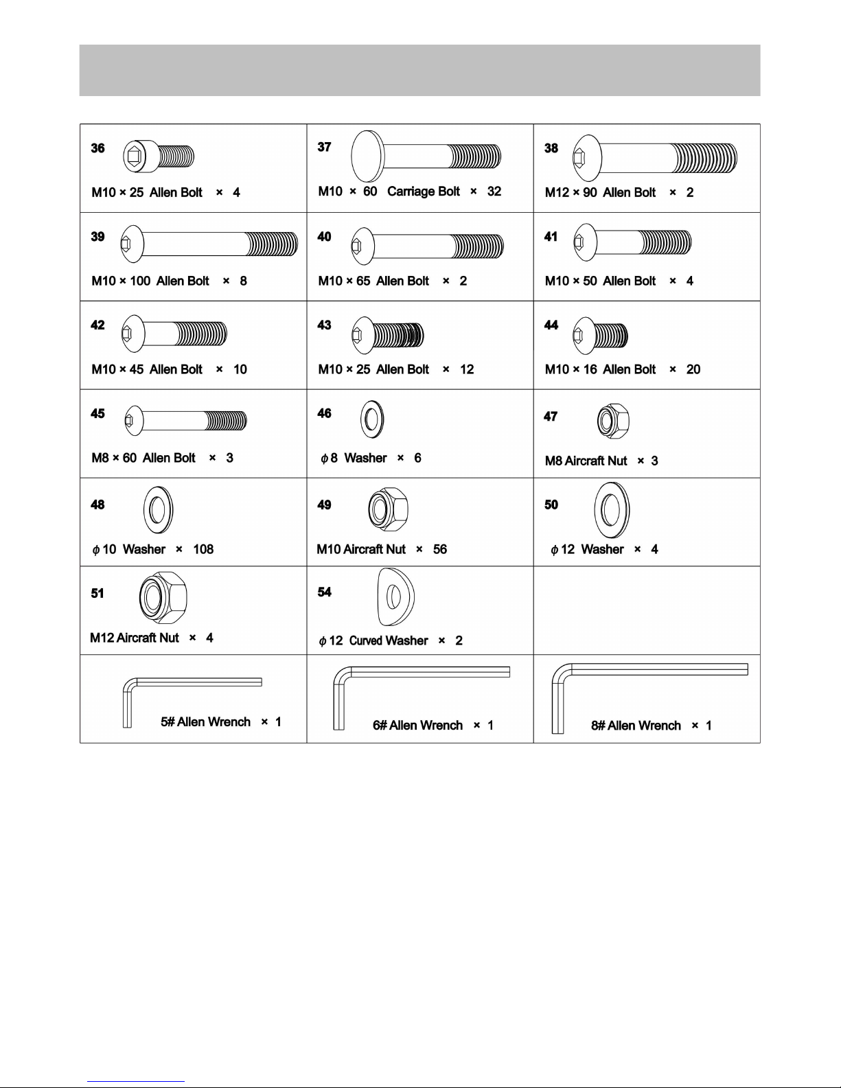
Components - Fixings
3
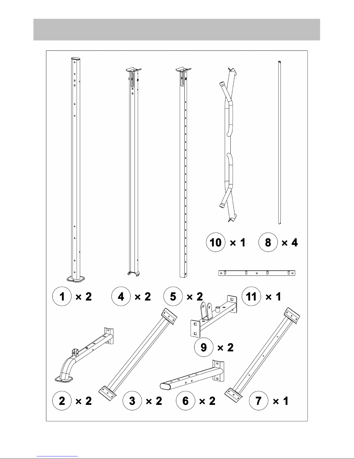
Components - Parts (1)
4
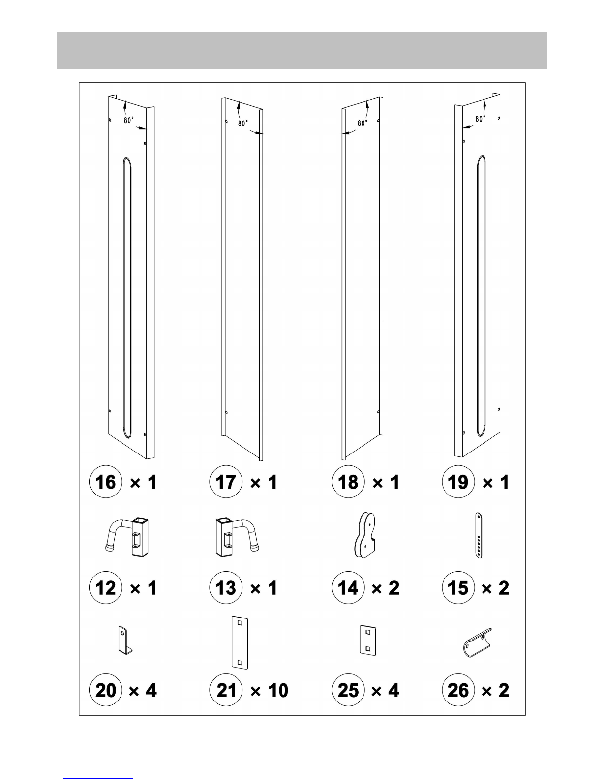
Components - Parts (2)
5
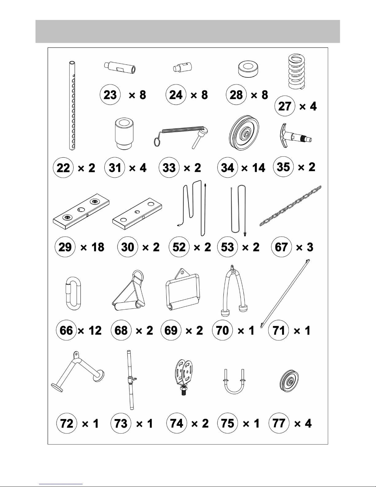
Components - Parts (3)
6
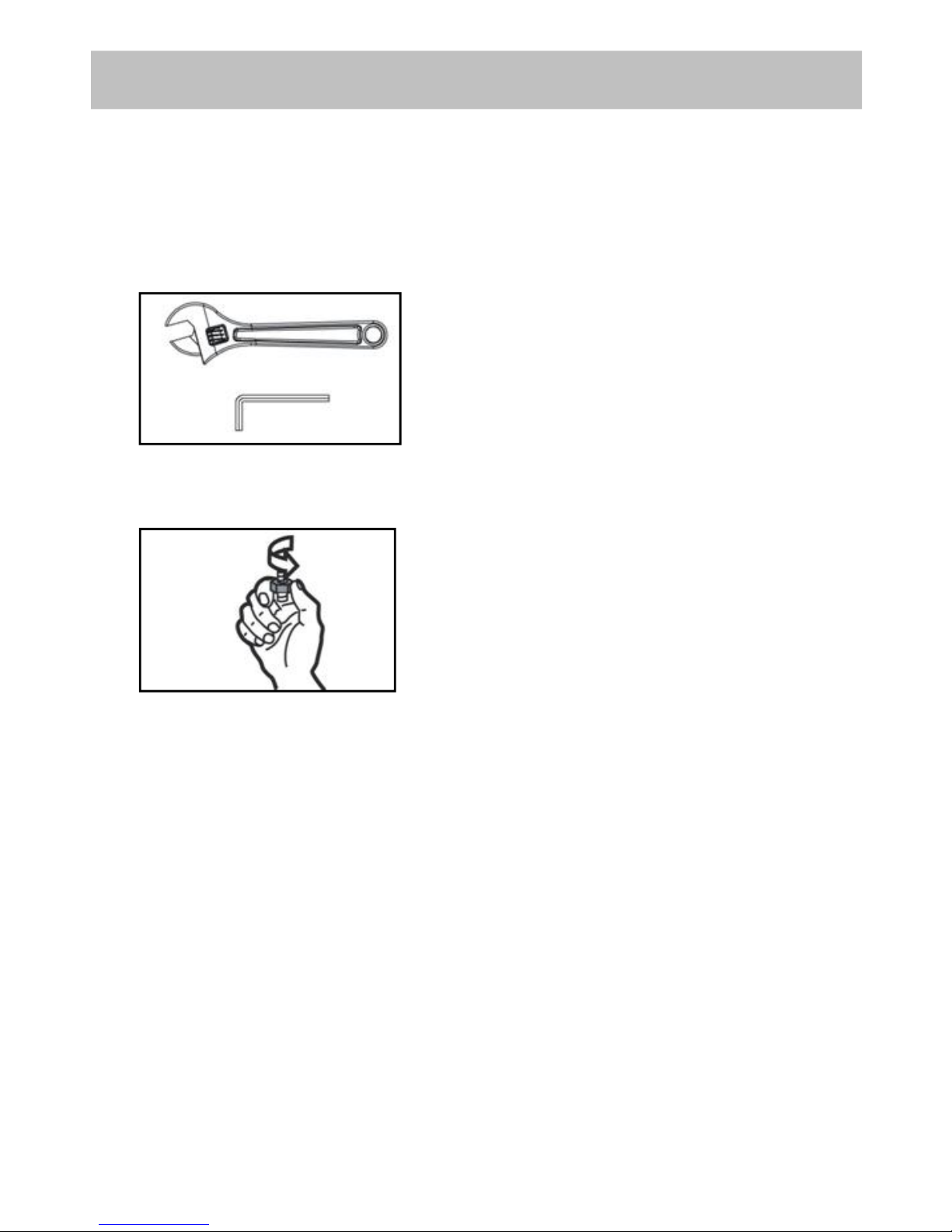
Tools: Adjustable spanner x 2
Attention:
It is strongly recommended to assemble the equipment by two or more people, otherwise it may
cause serious injury.
The icon indicates the spanner can be
directly used to tighten and secure
during assembly.
The icon indicates turn the bolt by hand
during assembly, but do not tighten
them so as not to affect next assembly
step.
Assembly Instructions
7
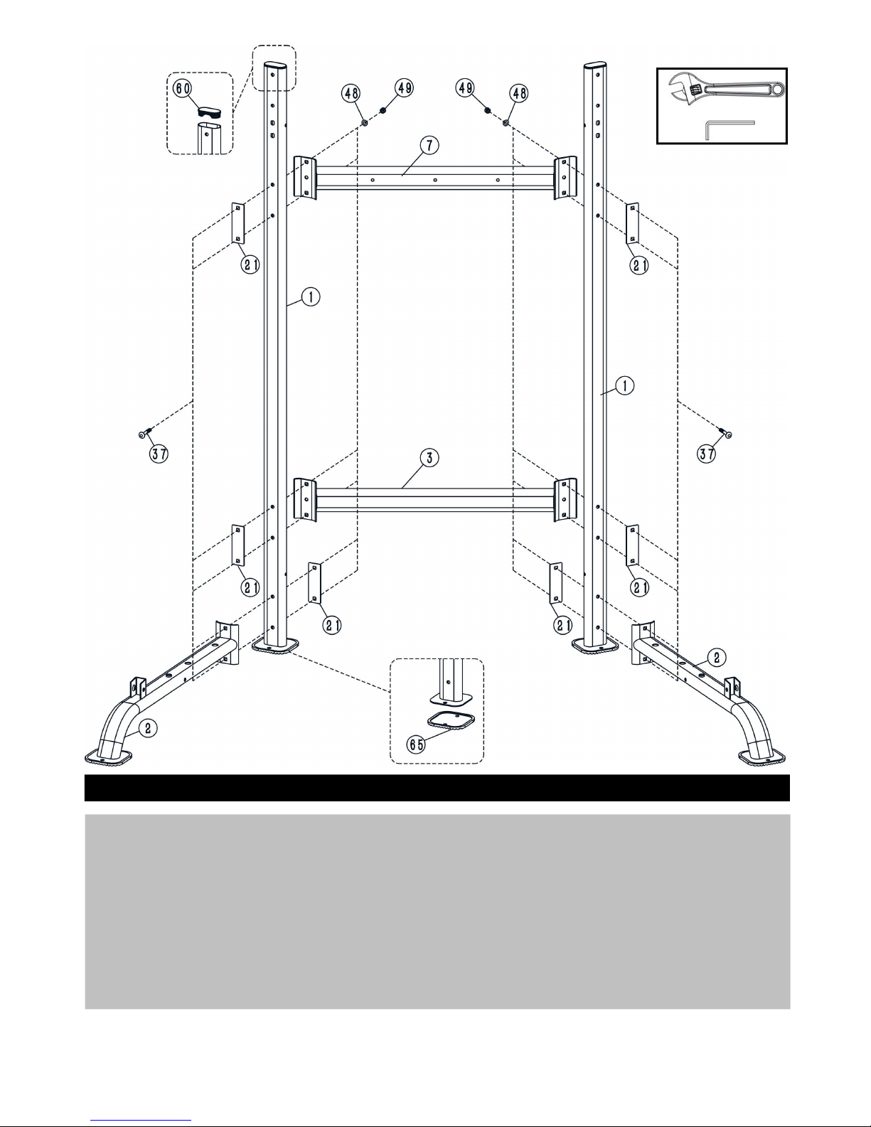
Step 1
1. Attach 2 x Base Frame (2) and 2 x Flat Bracket (21) to 2 x Rear Vertical Support (1) respectively using 2
x M10×60mm Carriage Bolts (37), 2 x φ10mm Washers (48) and 2 x M10 Aircraft Nuts (49).
2. Attach 1 x Cross Beam (3) and 2 x Flat Bracket (21) to 2 x Rear Vertical Support (1) respectively using 4
x M10×60mm Carriage Bolts (37), 4 x φ10mm Washers (48) and 4 x M10 Aircraft Nuts (49).
3. Attach 1 x Upper Connecting Frame (7) and 2 x Flat Bracket (21) to 2 x Rear Vertical Support (1)
respectively using 4 x M10×60mm Carriage Bolts (37), 4 x φ10mm Washers (48) and 4 x M10 Aircraft
Nuts (49).
Notes: The part (60) and (65) are pre-assembled.
8
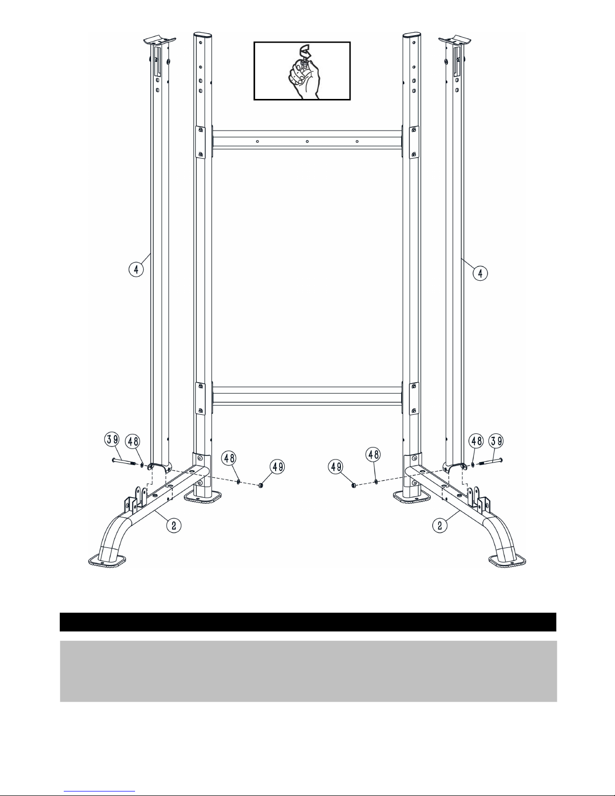
Step 2
1. Attach 2 x Middle Vertical Support (4) to 2 x Base Frame (2) respectively using 2 x M10×100mm Allen
Bolts (39), 2 x φ10mm Washers (48) and 2 x M10 Aircraft Nuts (49).
9
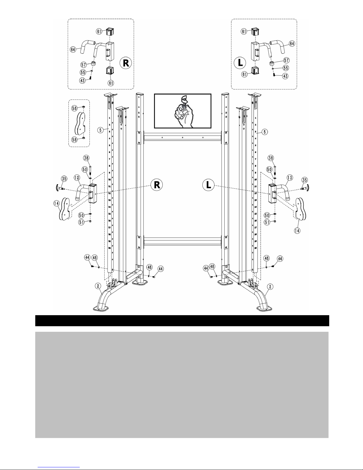
Step 3
1. Put 2 x Guide Tube (5) through the L&R Sliding Frames (12, 13), and respectively screw 1 x
M18×1.5×φ12 T-shaped Pin (35) in the bolts of the L&R Sliding Frame (12, 13), then secure the
M18×1.5×φ12 T-shaped Pin (35) to facilitate the L&R Sliding Frame (12) are adjustable on the Guide
Tube (5).
2. Put the U-shaped brackets of 2 x Base Frame (2) through 2 x Guide Tube (5) respectively, and then fix
2 x Guide Tube (5) to 2 x Base Frame (2) respectively using 2 x M10×16 Allen Bolts (44) and 2 x
φ10mm Washers (48).
3. Fix 2 x Double Floating Pulley Bracket (14) to the L&R Sliding Frame (12, 13) using 1 x M12×90mm
Allen Bolts (38), 2 x φ12mm Washers (50) and 1 x M12 Aircraft Nut (51).
Notes: Parts (43, 55, 57, 58, 61, 64) are pre-assembled.
10

Step 4
1. Attach 2 x Upper Frames (6) and 2 x Flat Brackets (21) to 2 x Middle Vertical Support (4) and Guide
Tube (5) respectively using 4 x M10×60mm Carriage Bolts (37), 4 x φ10mm Washers (48) and 4 x M10
Aircraft Nuts (49).
2. Connect 1 x Cross Beam (3) to 2 x Rear Vertical Support (1) and 2 x Upper Frame (6) using 4 x
M10×60mm Carriage Bolts (37), 4 x φ10mm Washers (48) and 4 x M10 Aircraft Nuts (49).
11

Step 5
1. Fix 2 x Guide Rods (8) to the right Base Frame (2) using 2 x M10×25mm Allen Bolts (43).
2. Put the Guide Rod (8) through 1 x Rubber Bumper (28), 1 x Shock Spring (27) and 1 x Rubber
Bumper (28) sequentially.
3. Put the Guide Rod (8) through 15× 5kg Selector Stems (29).
4. Respectively put 2 x Weight Stem Guiding Sleeve (31) into the 4kg Selector Stem (30), insert the
Selector Rod (22) into the 4kg Selector Stem (30), screw 2 x M10×25mm Allen Bolts (36) in the 4kg
Selector Stem (30) and fix the Selector Rod (22).
5. Put the Guide Rod (8) through 1 x 4kg Selector Stem (30).
6. Stick the weight sticker (32) as shown in the diagram, from top to bottom sticking 5kg, 10kg, 15kg,
20kg, 25kg, 30kg, 35kg, 40kg, 45kg, 50kg,55kg,60kg,65kg,70kg,75kg,80kg.
12

Step 6
Repeat Step 5 to assemble the left weight stack.
13

Step 7
1. Put left and right Guide Rod (8) through 2 x Guide Rod Holder (9).
2. Fix the 2 x Guide Rod Holder (9) to the middle between the L&R Middle Vertical Support (4) and the
Rear Vertical Support (1) using 4 x M10×60mm Carriage Bolts (37), 4 x φ10mm Washers (48), 4 x
M10 Aircraft Nuts (49) and 2 x Bracket (25).
14

Step 8
1. Fix the left and right Guide Rod Holder (9) to the Guide Rod (8) respectively using 2 x M10×25mm
Allen Bolts (43) and 1 x φ10mm Washer (48).
2. Fix the pulley bracket(74)to Selector Rod (22)
Notes: Parts (76) are pre-assembled.
15

Step 9
Attach the Hook Frame (11) to the Upper Connecting Frame (7) using 3 x M8×60mm Allen Bolts (45), 6 x
Ø8mm Washers (46) and 3 x M8 Aircraft Nuts (47).
16

Step 10
1. Attach the U-shape hook (75) to the Chin up bar Frame (10) using 2 x φ12 Curved Washers (54), 2 x
M12 Aircraft Nut (51).
2. Attach the Chin up bar Frame (10) to the middle of the 2 x Upper Frame (6) using 8 x φ10mm
Washers (48), 4 x M10 Aircraft Nut (49), 4 x M10×100mm Allen Bolts (39) and 2 x Arc Bracket (26).
Notes: Parts (43, 55, 56, 59, 63) are pre-assembled.
17

Step 11
1. Find out the end with threaded head of the Upper Cable (52) as shown in the diagram, thread the end
in sequence through the long notch on the right side of the Guide Tube (5), Middle Vertical Support (4)
and Guide Rod Holder (9), and finally screw H into the Guide Rod Holder (9).
2. Connect the Pulley φ114 A, B (34) and Upper Frame (52) to the Right Sliding Frame (12) using 1 x
M10×45 Allen Bolt (42), 2 x ø10mm Washers (48) and 1 x M10 Aircraft Nut (49), and ensure the cable
in pulley groove.
3. Connect the Pulley φ114 C (34) and Upper Frame (52) to the Guide Tube (5) using 1 x M10×65 Allen
Bolt (40), 2 x ø10mm Washers (48) and 1 x M10 Aircraft Nut (49), and ensure the cable in pulley
groove.
4. Connect the Pulley φ114 D (34) and Upper Frame (52) to the 2 x Double Pulley Bracket (15) and 1 x
L- Shaped Cable Protector (20) using 1 x M10×50 Allen Bolt (41), 2 x ø10mm Washers (48) and 1 x
M10 Aircraft Nut (49), and ensure the cable in pulley groove.
5. Fix the Pulley φ114 E (34) and Upper Frame (52) to the Guide Tube (5) using 1 x M10×100 Allen Bolt
(39), 2 x ø10mm Washers (48) and 1 x M10 Aircraft Nut (49), and ensure the cable in pulley groove.
6. Connect the Pulley φ90 F (77) and the Guide Tube (52) to the Guide Rod Holder (9) using 1 x
M10×45mm Allen Bolt (42),2 x ø10mm Washers (48) and 1 x M10 Aircraft Nut (49), and ensure the
cable in pulley groove.
7. Connect the Pulley φ90 G (77) and the Guide Tube (52) to the pulley bracket (74) using 1 x M10×45mm
Allen Bolt (42),2 x ø10mm Washers (48) and 1 x M10 Aircraft Nut (49), and ensure the cable in pulley
groove.
18

Step 12
Repeat the step 11 to assemble the left Upper Cable (52).
19

Step 13
1. Put the End A of the Adjustment Cable (53) through the sleeve on the right side of the Right Sliding
Frame (12) as shown in the diagram, then screw the End D in the nut on the Base Frame (2).
2. Connect the Pulley φ114 B (34) and Adjustment Cable (53) to the Base Frame (2) using 1 x
M10×45mm Allen Bolt (42), 2 x ø10mm Washers (48) and 1 x M10 Aircraft Nut (49), and ensure the
cable in the pulley groove.
3. Connect the Pulley φ114 C (34) and Adjustment Cable (53) to 1 x L- Shaped Cable Protector (20) and
2 x Double Pulley Bracket (15) using 1 x M10×50mm Allen Bolt (41), 2 x ø10mm Washers (48) and 1 x
M10 Aircraft Nut (49).
4. Cable tension can be adjusted by the End D of the Adjustment Cable (53).
20

Step 14
Repeat step 13 to assemble the left Adjustment Cable (53).
21

Step 15
1. Respectively attach 8 x φ16×M10×65 Axle (23) to the inside of the 2 x Rear Vertical Support (1) and 2 x
Middle Vertical Support (4).
2. Respectively attach 8 x φ16×M10×35 Axle (24) to the outside of the 2 x Rear Vertical Support (1) and 2 x
Middle Vertical Support (4).
22

Step 16
1. Fix the Right Inside Weight Stack Cover (18) to 4 x φ16×M10×65 Axle (23) using 4 x M10×16mm Allen
Bolts (44) and 4 x ø10mm Washers (48).
2. Fix the Right Outside Weight Stack Cover (16) to 4 x φ16×M10×35 Axle (243) using 4 x M10×16mm
Allen Bolts (44) and 4 x ø10mm Washers (48).
23

Step 17
1. Fix the Left Inside Weight Stack Cover (16) to 4 x φ16×M10×65 Axle (23) using 4 x M10×16mm Allen
Bolts (44) and 4 x ø10mm Washers (48).
2. Fix the Left Outside Weight Stack Cover (17) to 4 x φ16×M10×35 Axle (24) using 4 x M10×16mm
Allen Bolts (44) and 4 x ø10mm Washers (48).
3. Secure all the bolts and nuts.
24

Step 18
C-Shaped Lock Ring φ7×66(66)or 15 Joints Chain(67)connect Upper Cable(52)can be chosed
as Optional Accessory,other spare parts can be hung with Hook Frame(11)

Part #
Description
Qty
Part #
Description
Qty
1
Rear Post
242M10×45mm Allen Bolt
10
2
Base Frame
243M10×25mm Allen Bolt
12
3
Cross Beam
244M10×16mm Allen Bolt
20
4
Middle Vertical Support
245M8×55mm Allen Bolt
3
5
Guide Tube
246φ8mm Washer
6
6
Upper Frame
247M8 Aircraft Nut
3
7
Upper Connecting Frame
148φ10mm Washer
108
8
Guide Rod
449M10 Aircraft Nut
56
9
Guide Rod Holder
250φ12mm Washer
4
10
Chin up bar frame
151M12 Aircraft Nut
4
11
Hook Frame
152Upper Cable
2
12
Right Sliding Frame
153Adjustment Cable
2
13
Left Sliding Frame
154φ12 Curved Washer
2
14
Cross Double Floating Pulley Bracket
255M10 Serrated Washer
4
15
Double Pulley Bracket
456φ28 End Cap
2
16
Left Inside Weight Stack Cover
157φ25End Cap
2
17
Left Outside Weight Stack Cover
158Bushing φ25×φ22×φ12×10
4
18
Right Inside Weight Stack Cover
159End Cap φ28×2.5
2
19
Right Outside Weight Stack Cover
160End Cap 40×80×2.0
4
20
L- Shaped Cable Protector
461Induction Sleeve □60×2.0×□45×60
4
21
Flat Bracket
1062Weight stack cover decorations
6
22
Selector Rod
263Handle Grip φ27×φ33×540
2
23
Axle φ16×M10×65
864Handle Grip φ24×φ34×240
2
24
Axle φ16×M10×35
865Base Rubber Cushion
4
25
Bracket
466C-Shaped Lock Ring φ7×66
12
26
Arc Bracket
26715 Joints Chain
3
27
Shock Spring φ33×φ21×φ6×70
468Single Strap
2
28
Rubber Bumper 40×φ20×15
869D-Shaped Single Strap
2
29
5kg Selector Stem 90×320
1870Triceps Rope/ double knobs
1
30
4kg Selector Stem 90×270
271Push-pull Bar
1
31
Weight Stem Guide Sleeve
472V-shaped Handle
1
32
Weight Sticker
273Upright Handle
1
33
φ10×80 Magnet Pin
274Pulley Bracket
2
34
Pulley φ114
1475U-shape hook
1
35
M18×1.5×φ12 T- Shaped Pin
276M16×2.0 Nut
2
36
M10×25mm Allen Bolt
477Pulley φ90
4
37
M10×60mm Carriage Bolt
32
38
M12×90mm Allen Bolt
2
5# Allen Wrench
1
39
M10×100mm Allen Bolt
8
6# Allen Wrench
1
Parts List
25

40
M10×65mm Allen Bolt
2
8# Allen Wrench
1
41
M10×50mm Allen Bolt
4
26

GARLANDO SPA
Via Regione Piemonte, 32 - Zona Industriale D1
15068 - Pozzolo Formigaro (AL) - Italy
contact@toorxprofessional.it
www.toorxprofessional.it
 Loading...