


INSTRUCTION
Rev : 0000
Ed : 02/17
ASSEMBLYINSTRUCTIONS
RUCTIONS
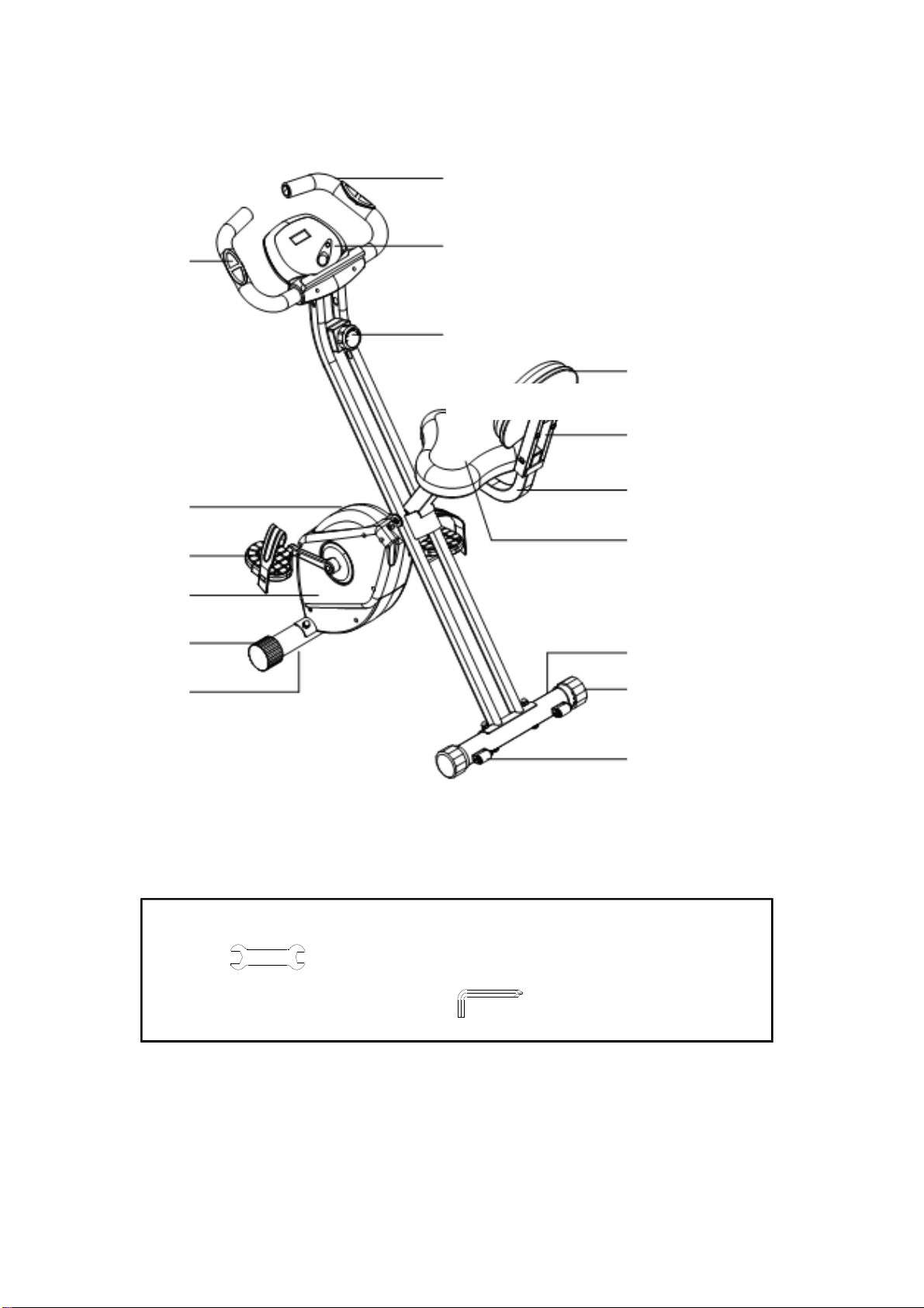
PRODUCT
OVERVIEW
Rear Stabilizer
Left Chain Cover
Back Support
Pulse Sensor
Top Cover
Left Pedal
Handlebar
Meter
Adjustment Knob
Back Cushion
Back Frame
Seat
End Cap
Front Stabilizer
THEFOLLOWINGTOOLS ARE INCLUDED FOR ASSEMBLY:
Wrench
Allen Wrench (5mm) w/ Screwdriver
Wheel End cap
Wheel
ASSEMBLYINSTRUCTIONS
RUCTIONS
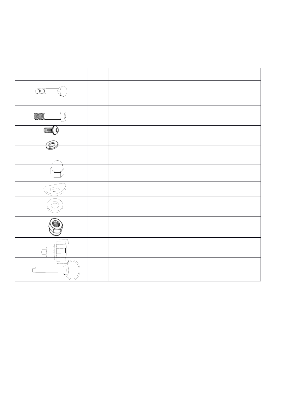
HARDWARE IDENTIFICATION CHART
adyattachedtothepart.
Figure No. Description Qty
D5
D8
Carriage Bolt (M8 * 1.25 * 60mm)
Carriage Bolt (M8 * 1.25 x*48mm)
4
2
D7 Bolt, Button Head (M6*1 *40mm) 4
D52 Bolt, Button Head (M6* 12mm) 4
D53 Spring Washer (M6) 4
D22 Acorn Nut (M8*1.25) 4
D23 Arc Washer (M8) 4
D24 Washer (M8) 6
D25 Nut M8 2
D1 Adjustment Knob 1
D2
Pull Pin
1
ASSEMBLYINSTRUCTIONS
RUCTIONS
ASSEMBLY INSTRUCTIONS
Place all parts from the box in a cleared area and position them on the floor in front of you.
Remove all packing materials from your area and place them back into the box. Do not dispose of
the packing materials until assembly is completed. Read each step carefully before beginning.
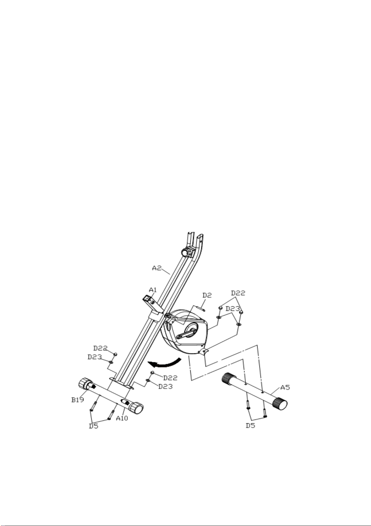
STEP 1: Unfold the Rear Frame (A2) away from the Main Frame (A1). Locking the frame
assembly in unfold position by inserting the Pull PIN (D2) into the hole in the Rear Frame
(A2).
STEP2: Attach the Rear Stabilizer (A10), the one with Transport Wheels (B19), to the Rear
Frame (A2) with the wheels facing backward. Secure with Carriage Bolts
(M8*1.25*60mm) (D5), Acorn Nuts (M8) (D23), and Arc Washers (M8*1.25) (D22).
STEP 3: Attach the Front Stabilizer (A5) to the Main Frame (A1) with Carriage Bolts
(M8*1.25*60mm) (D5), Acorn Nuts (M8) (D23), and Arc Washers (M8*1.25) (D22)..
ASSEMBLYINSTRUCTIONS
RUCTIONS
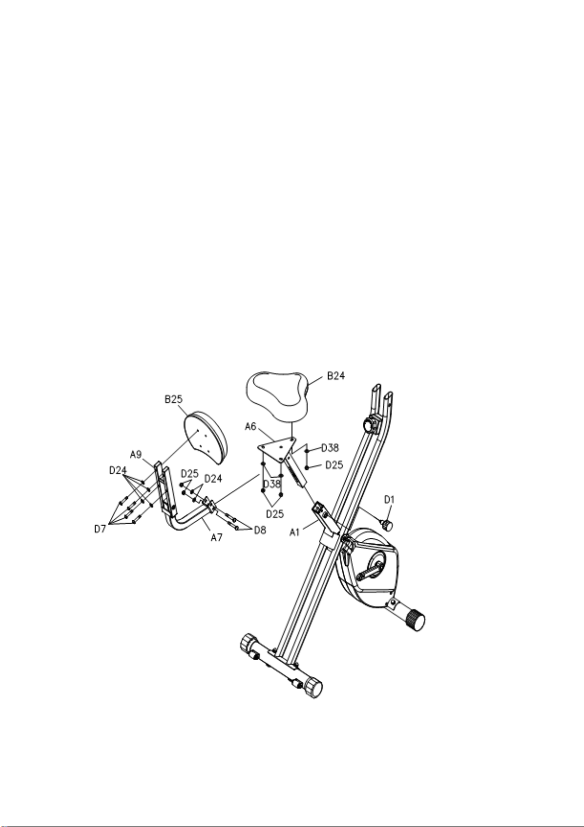
STEP 4: Attach the Seat (B24) to the Seat Post (A6) with Nylock Nuts (M8) (D25) and Washer
(M8) (D38). Insert the Seat Post (A6) into the Main Frame (A1) and secure with the
Adjustment Knob (D1).
NOTE:
Make sure that the pin on the Adjustment Knob (D1) is inserted into one of the holes in Seat
Post (A6).
STEP 5: Attach the Back Support (A7) and Back Frame (A6) by using Carriage Bolt
(M8*1.25*48mm) (D8) and Washer (M8) (D24).
STEP 6: Attach the Back Post (B25) to the Back Support (A9) with Hex Head Round Bolt M8X40
and Washer (M8) (D24).

ASSEMBLYINSTRUCTIONS
RUCTIONS
STEP7: Insert the Handle Bar (A8) into the Rear Frame (A2) and securing by using the Bolt,
Button Head (M6* 12mm) (D52) and Spring Washer (M6)(D53). Then Connecting the
Connection Wire (C2) and Sensor (C13).

STEP9: Tighten the Left Strap (B29) and Right Strap (B30) to the Left Pedal (B27) and Right
Pedal (B28). Lock and tight the Left Pedal (B27) and Right Pedal (B28) on the Left
Crank (C5) and Right Crank (C6) by using the Wrench.
ASSENBLY INSTRUCTIONS
9

OPERATIONAL INSTRUCITONS
KEY FUNCTIONS:
MODE: This key lets you to select and lock on to a parcular funcon
you want.
FUNCTIONS:
SCAN: Automatically scans each function of SPEED,
DISTANCE,TIME, ODOMETER, CALORIES and PULSE.
in sequence, display changes every six seconds. Press
and release the button until "SCAN" appears on the
display.
SPEED: Displays the current speed from zero to 999.9 KM per hour.
DISTANCE: Displays the distance from zero to 999.9 KM
TIME: Displays the me from one second up to 99:59 minutes.
ODOMETER: Displays the total accumulated distance you have traveled from zero to 9999 KM. The
total accumulated distance is retained when the meter is turned off.
CALORIES: Displays the calories burned from zero to 999.9 Kcal.
The calorie readout is an estimate for an average user. It should be used only as a
comparison between workouts on this unit.
PULSE: Displays your pulse rate in beats per minute. To display pulse, select the PULSE MODE and
grasp the pulse sensors on the Desktop, one in each hand. The heart icon will begin flashing
when the ELECTRONIC METER senses your pulse. Your pulse will be displayed
approximately five (5) seconds after the heart icon is displayed. If the heart icon does not
appear, relax your grip or change your grip on the pulse sensors.
NOTE:
1. NOTE: The meter will shut off automatically after four minutes of inactivity. All function values
will be kept. Press the button and hold it down for two seconds to reset all functions to zero, except
ODOMETER.
2. The ODOMETER will be reset to zero after batteries are removed for battery replacement or
storage of the unit.
HOW TO INSTALL AND REPLACE BATTERIES
1. Open the Battery Door on the back of the meter.
2. The meter operates with two AAA batteries, the batteries are not included. Refer to the illustration to install or
replace the batteries.
NOTE:
1. Do not mix a new battery with an old battery.
2. Use the same type of battery. Do not mix an alkaline battery with another type of battery.
3. Rechargeable batteries are not recommended.
4. Ultimate disposal of battery should be handled according to all state laws and regulations.
5. Do not dispose of batteries in fire.

LOAD ADJUSTMENT
To increase the load, turn the Adjustment Knob (B32) clockwise.
To decrease the load, turn the Adjustment Knob (B32) counterclockwise.
There are eight levels for the load adjustment.
SEAT ADJUSTMENT
Proper seat adjustment is important.
1. Turn the Adjustment Knob (D1) to loosen, then pull the
Adjustment Knob (D1) to release the pin. Slide the Seat
Post (A6) until the Seat (B24) is at the proper height.
Release the Adjustment Knob (D1) making sure the pin
catches in one of the holes of the Seat Post (A6) and
tighten the Adjustment Knob (D1).
2. Sit on the seat and place your feet on the pedals. You
should be able to move through a complete pedal stroke
without locking your knees or shifting your hips on the
seat. The seat is too close to the pedals if you have more
than as light bend in your knees at the bottom of the pedal
stroke. The seat is too far from the pedals if you have to
completely straighten your knees at the bottom of the
pedal stroke. Refer to the illustration.
CAUTION:
1. Do not attempt to adjust the seat while you
are on the BIKE
2. Always tighten the Adjustment Knob (D1) a$er
adjusng the seat to a new posion.

STORAGE
1. To store the BIKE, simply keep it in a clean dry place.
2. To avoid damage to the electronics, remove the batteries before storing the BIKE for one year or more.
3. To move the BIKE, hold the HANDLEBAR and tilt the BIKE onto the Wheels of the Stabilizer at the
front.
4. Follow the illustrated process below to fold the BIKE.
A. Remove the Pull Pin (D2), fold the Rear Frame (A2) forward. Insert the Pull Pin (D2) back into the Rear
Frame (A2) after folding.
B. Remove the Pull Pin (D2) from the Rear Frame (A2).Fold the Rear Frame (A2) close to the Main Frame
(A1) and lock it in folded position with the Pull Pin (D2).
NOTE: Make sure the Pull Pin (D2) goes through the holes on both sides of the Rear Frame (A2) and the
tube on the Main Frame (A1).
12

PRODUCT PARTS DRAWING
TOCONTACTCUSTOMERSERVICE
16

PARTS LIST
A. Welding Parts
No. Description QTY
A1 Main Frame 1
A2 Rear Frame 1
A5 Front Stabilizer 1
A6 Seat Support 1
A7 Back Frame 1
A9 Back Support 1
A10 Rear Stabilizer 1
A12 Magnetic Bracket 1
A13 Shaft 1
A15 Handlebar 1
B. Plastic Parts
No. Description QTY
B1 Left Chain Cover 1
B2 Right Chain Cover 1
B3 Top Cover 1
B12 Sensor Bracket 1
B13 Bushing 1
B14 Plastic Bushing 6
B16 Plastic Washer Φ8.5*Φ20*2.0T 2
B17 Rubber Cushion 1
B18 Leveling Cap 2
B19 Wheel 2
B20 Inner Plug 2
B21 Tube Bushing S30*30 1
B22 Tube Bushing S15*30 4
B24 Seat 1
B25 Back Cushion 1
B26 Foam Grip 400 2
B27 Left Pedal 1
B28 Right Pedal 1
B29 Left strap 1
B30 Right strap 1
B31 Crank Cap 2
B32 Adjustment Knob 1
B35 Plastic WasherΦ10.2*Φ14 2
TOCONTACTCUSTOMERSERVICE
18

B37 Stopper 1
B38 Endcap 2
B39 Bearing Housing 2
B40 Hand grip 2
B43 Grommet Plug 4
B44 Plug 1
C. Electrical parts
No. Description QTY
C1 Meter 1
C2 Connection Wire 1
C5 Left Crank 1
C6 Right Crank 1
C7 Flywheel 1
C8 V-Ribbed Belt (230J) 1
C9 V-Ribbed Belt(240J) 1
C10 Pulley w/ Shaft 1
C11 Pulley Shaft 1
C12 Pulley 1
C13 Sensor 1
C14 Ball Bearing (6000ZZ) 2
C15 Ball Bearing (6200ZZ) 1
C16 Ball Bearing (6003ZZ) 2
C17 Idler Shaft 1
C18 Magnet 6
C19 Idler Shaft 1
C20 Magnet 1
C21 Hand Pulse 4
C22 Hand pulse Line
1
D. Hardware
No. Description QTY
D1 Adjustment Knob 1
D2 Pull Pin 1
D4 Allen Wrench 1
D5 Carriage Bolt M8*60 4
D6 Hex Head Bolt M6*45 2
D7 Bolt, Button Head M8*40 4
D8 Carriage Bolt M8*48 2
TOCONTACTCUSTOMERSERVICE
19

D9 Bolt, Button Head M8*75 1
D10 Bolt, Button Head M8*20 2
D11 Eye Bolt M6 2
D15 Screw, Round Head ST4.2*16 6
D17 Bolt, Round Head (M6*12mm) 8
D19 Wave Washer S10 1
D20 Screw, Round Head ST4.2*25 1
D21 Flange Nu M10*1.25 2
D22 Acorn Nut M8 4
D23 Arc Washer M8 4
D24 Washer M8 8
D25 Nylock Nut M8 6
D26 Nut M10 2
D27 U-Shape Bracket 2
D28 Nylock Nut M6 2
D29 C Ring Φ17.0 6
D30 C Ring Φ10 2
D31 Wave Washer S17 1
D32 Spring Washer M8 1
D33 Large Washer(ø8.2*ø25*2mm) 2
D34 Nut M10 1
D35 Carriage Bolt M4X10 1
D36 Nylock Nut M10 1
D37 Nylock Nut M8 1
D38 Washer M8 3
D39 Nylock Nut M6 2
D41 Bearing Housing Cover 2
D42 Spring 1
D44 Washer (M5) 1
D47 Wrench 13-15 1
D49 Screw, Round Head ST4.0*20 2
D51 Screw, Round Head Self-Tapping ST4.2*16 4
D52 Bolt, Button Head (M6* 12mm) 4
D53 Spring Washer (M6) 4
D54 Bolt, Round Head M5*20 1
TOCONTACTCUSTOMERSERVICE
20

GARLANDO SPA
Via Regione Piemonte, 32 - Zona Industriale D1
15068 - Pozzolo Formigaro (AL) - Italy
www.toorx.it - info@toorx.it
 Loading...