

Ed: 02/17
INSTRUCTION
Rev: 0000
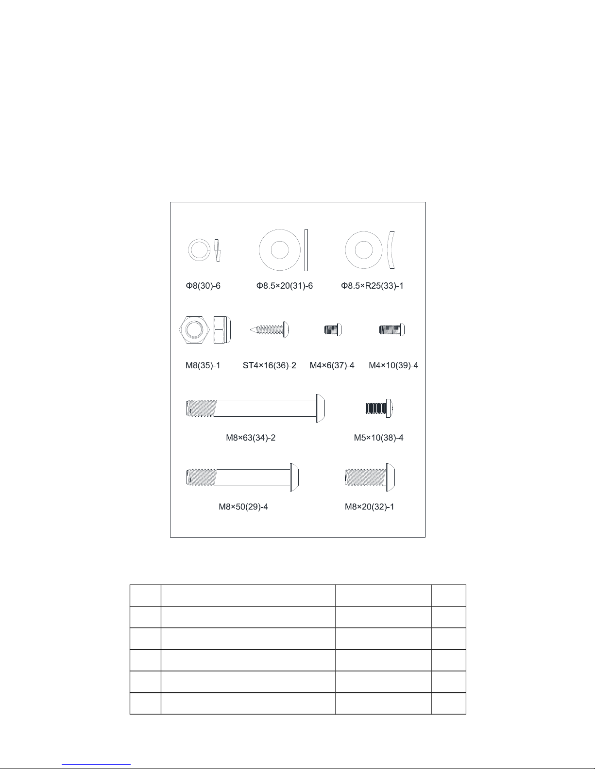
Pre-assembly Notes
Open the boxes:
Make sure to inventory all the parts that are included in the box. Check the hardware
chart
of a full count of the number of parts included for proper assembly . If any of the parts
are
missing, contact with the dealer.
NO. NAME SPECIFICATION QTY
29 Allen C.K.S. half thread screw M8×50×20 4
30 Spring washer Φ8 6
31 Flat washer Φ8.5×Φ20×t1.5 6
32 Allen C.K.S. full thread screw M8×20 1
33 Curved washer Φ8.5×R25×t2.0 1
2
34 Allen C.K.S. half thread screw M8×63×20 2
35 Hex self-locking nut M8 1
36 Philips C.K.S. self-tapping screw ST4×16 2
37 Philips pan head full thread screw M4×6 4
38 Philips pan head full thread screw M5×10 4
39 Philips pan head full thread screw M4×10 4
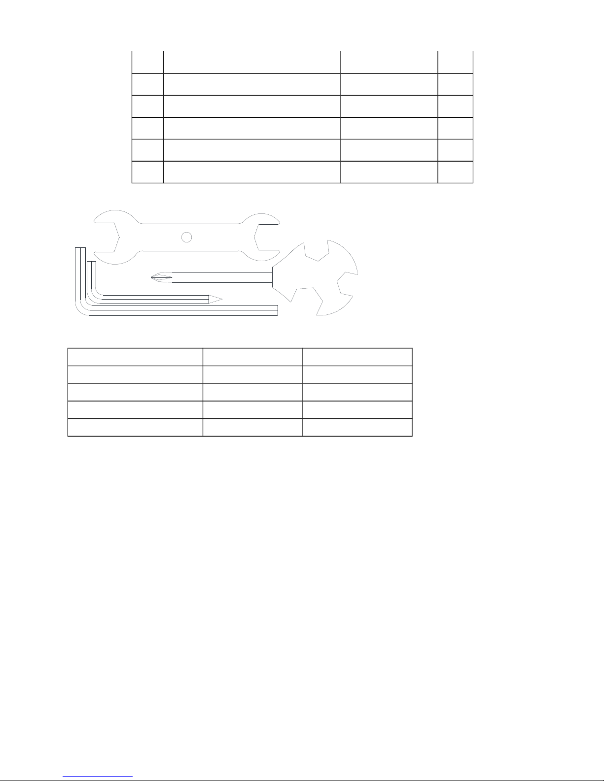
GATHER YOUR TOOLS
Before starting the assembly of your unit,gather the necessary tools.Having all of the
equipment at hand will save time and make the assembly quick and hassle-free.
CLEAR YOUR WORK AREA
Make sure that you have cleared away a large enough space to properly assemble the
unit. Make sure the space is free from anything that may cause injury during assembly.
After the unit is fully assembled, make sure there is a comfortable amount of free area
around the unit for unobstructed operation.
NOTE: Each step number in the assembly instructions tells you what you will be doing.
Read and understand all instructions thoroughly before assembling the treadmill.
Name Specification QTY
L-shape wrench 5×80×80S 1
L-shape wrench 6×40×120 1
Cross spanner 15#&17# 1
Cross open spanner 1
3
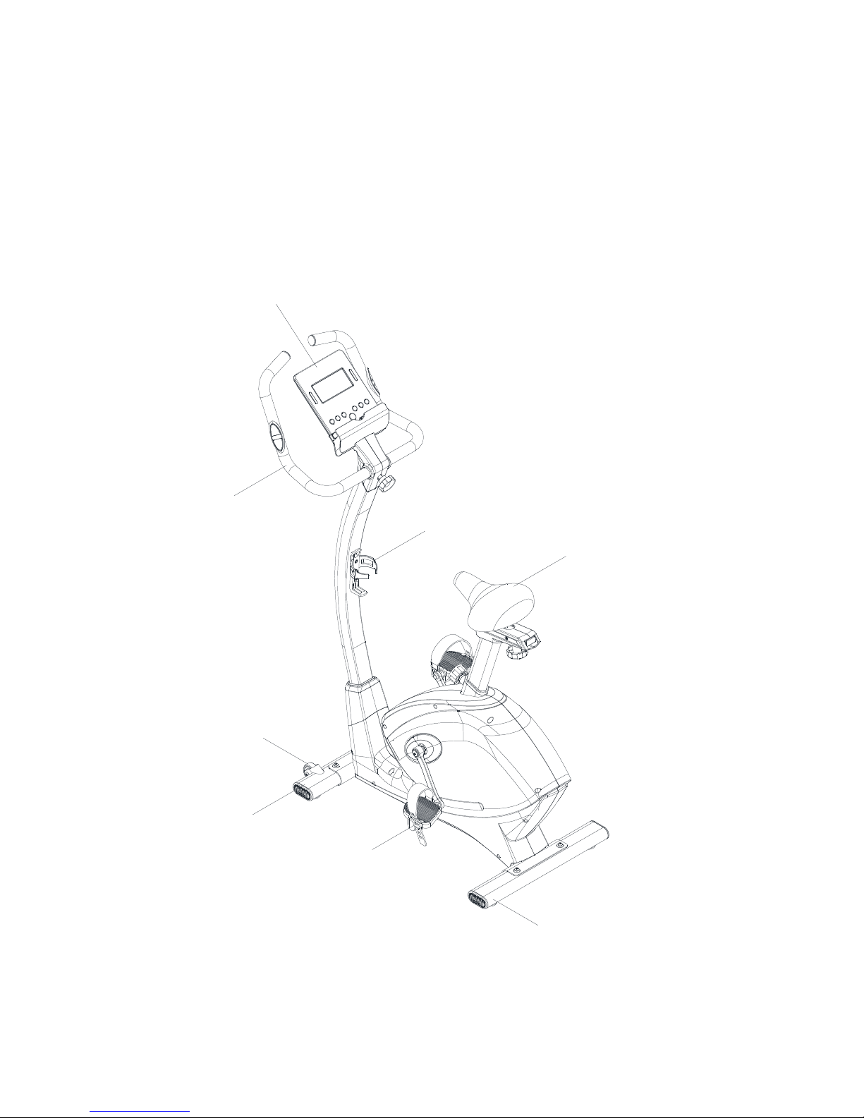
Product instruction
Technical information
4
Bottle holder
Handle bar
Controller
Motor belt
Pedal
Wheel
Front stabilizer
Rear stabilizer
Saddle
Console
DIMENSION Unfold
:
1100x530x1400mm
FLYWHEEL One -way, Φ280/6kg
RESISTANCE
FRAGMENT
32 levels
UP&DOWN 152.4 mm distance
FRONT&BACK 70mm distance
*WE
RESERVE THE RIGHT TO AMEND THE PRODUCT WITHOUT PRIOR NOTICE.
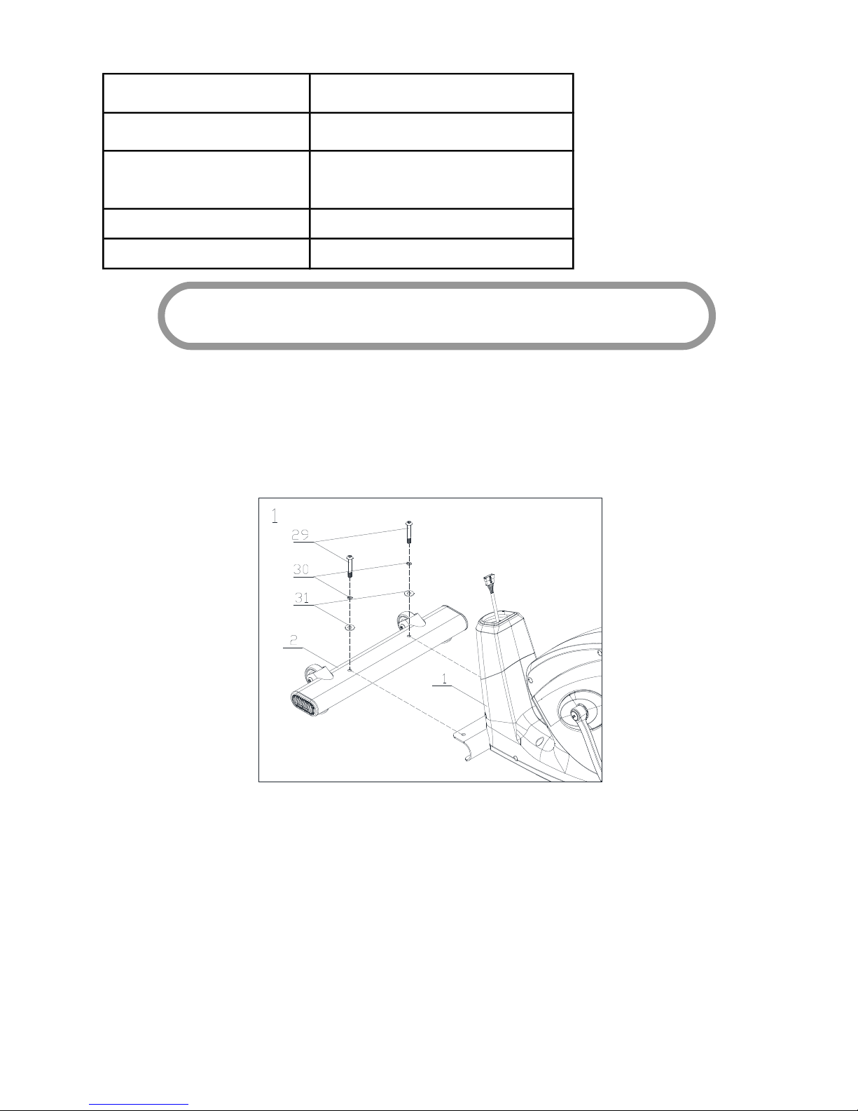
Step 1: Attach the front stabilizer (2) to the main frame (1) with flat washer(31), spring
washer(30) and Allen C.K.S. half thread screw(29).
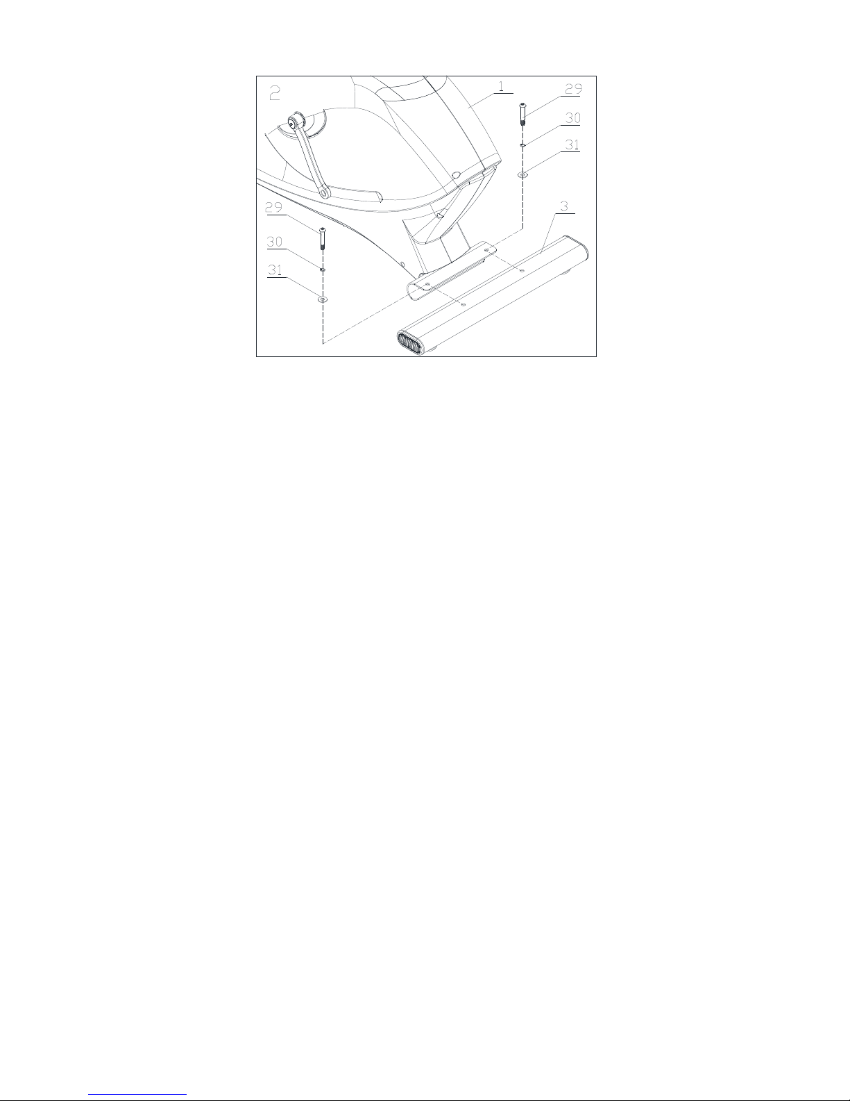
Step 2: Attach the rear stabilizer (3) to the main frame (1) with flat washer(31), spring
washer(30) and Allen C.K.S. half thread screw(29).
5
ASSEMBLY INSTRUCTIONS
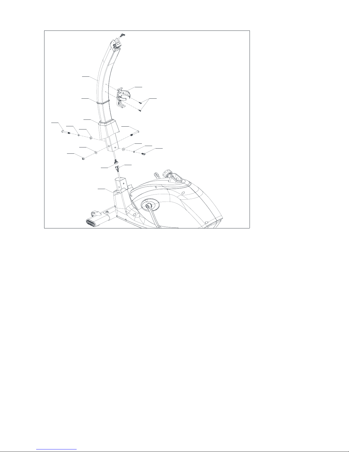
Step 3:
1.Attach the
Upright post decoration strip
(46) to the upper upright post(4),take upright
post cover(19) off from the main frame(1) and cover it on the upper upright post.(4)
2.Connect Motor communication wire (12) and Console communication wire (13).
3. Attach upper upright post(4) to the main frame(1) with Curved washer( 33), spring
washer(30), Allen C.K.S. half thread screw(34) and flat washer(31), spring washer(30),
Allen C.K.S. full thread screw(32) and flat washer(31),Allen C.K.S. half thread screw( 34),
Hex self-locking nut(35).
4.Attach upright post cover(19) and
Upright post decoration strip
(4 6 ) to the main
frame(1).
5.Attach bottle holder(20) to upper upright post(4) with Philips pan head full thread
screw(36).
Tip : Put the communication wires and r esistance adjust knob wire into the upright
post,and make sure all screws are in the hexagonal hole before tighten all the bolts.
6
31
30
32
35
31
34
19
1
33
30
34
3
13
12
4
46
20
36
Step 4:
Attach the Pedal(L)(5) and Pedal(R)(6) to the Main frame(1),then tighten the bolts.
7

Step 5:
1.
Loose the Rotary hand bolt(21),attach the Saddle post (7) to the
Main frame(1),then tighten the Rotary hand bolt(21).
5
7
1
21
Step 6:
8

1,Attach the saddle adjustment set (60) to the saddle post (7) and place it onto correct
position .Lock them with bushing (23) and rotary knob (22) .
2, Put the saddle (8) onto the saddle adjustment set (60) and lock it tightly .
3, Attach the saddle cover(L)(24) and saddle cover(L)(25) to the saddle post(7),and use
Philips pan head full thread screw(37) to tighten them.
6
8
25
37
37
24
7
21
23
22
60
Step 7:
1. Handle pulse connection wire
(16)
through the Upright post(4),and attach the
9

Handlebars(9) to Upright post(4),tighten with rotary knob(26).
2. Attach Console fixed piece(10) to the Upright post(4),tighten with Philips C.K.S. full
head screw(38).
Tip: Make sure all screws are in the hexagonal hole before tighten all the bolts.
7
4
38
38
10
9
26
16
Step 8:
10

1. C o n n e c t t h e Console communication wire( 1 3 ) a n d Console connection
wire(18),connect the Handle pulse connection wire(16) and Console outset(17).
2. Attach the Console(11) to the Console fixed piece(10),tighten with Philips C.K.S. full
head screw(40).
3. Att ac h the Handlebar cover(L)(2 7 ) a n d Handlebar cover(R)(28) through the
Handlebars(9) to the Upright post(4),tighten with Philips C.K.S. full head screw(39).
Tip: Make sure all screws are in the hexagonal hole before tighten all the bolts.
8
11
10
9
40
27
39
28
39
18
17
16
13
Workout tips:
1,User need to put the feet completely inside the pedal, and to adjust the resistance of
magnet control according to user.
2,Since the machine with double flywheels and it will have huge moment of inertia, when
the user stop before high speed, the user should minimize the resistance and lower the
speed, to avoid hurt the user’s leg by the moment of inertia of left and right pedal
3,The machine should be put on flat floor and have enough space for workout
Half-drawing for assembly
11

29
30
31
29
30
31
29
30
31
31
30
32
31
34
19
33
30
34
5
6
7
25
37
37
24
23
22
26
38
38
9
40
10
11
39
27
28
39
17
13
2
3
21
16
1
18
13
12
4
46
20
36
8
60
35
12

Part list
NO. NAME SPECIFICATION QTY
1
Main frame
1
2
Front stabilizer
1
3
Rear stabilizer
1
4
Upright post
1
5
Pedal(L)
1
6
Pedal(R)
1
7
Saddle post
1
8
Saddle
1
9
Handlebars
1
10
Console fixed piece
1
11
Console
1
12
Magnetic sensor wire
1
13
Console communication wire
1
14
Resistance adjust knob wire
1
15
Resistance adjust knob
1
16
Handle pulse connection wire
2
17
Console outset
2
18
Console connection wire
1
19
Upright post cover
1
20
Bottle holder
1
21
Rotary hand bolt
Φ56×M16×P1.5 1
13

22
Handlebar rotary knob
Φ60×31×M10×20 1
23
Bushing
Φ10.5×Φ14×10 1
24
Saddle cover(L)
1
25
Saddle cover(R)
1
26
Rotary knob
Φ54×82×M8×30 1
27
Handlebar cover(L)
1
28
Handlebar cover(R)
1
29
Allen C.K.S. half thread screw
M8×50×20 4
30
Spring washer
Φ8 6
31
Flat washer
Φ8.5×Φ20×t1.5 6
32
Allen C.K.S. full thread screw
M8×20 1
33
Curved washer
Φ8.5×R25×t2.0 1
34
Allen C.K.S. half thread screw
M8×63×20 2
35 Hex self-locking nut M8 1
36
Philips C.K.S. self-tapping screw
ST4×16 2
37
Philips pan head full thread screw
M4×6 4
38
Philips pan head full thread screw
M5×10 4
39
Philips pan head full thread screw
M4×10 4
40
Philips pan head full thread screw
M5×10 4
46
Upright post decoration strip
1
60
Saddle adjustment set
1
14

Drawig for assembly
15

16
59
15
14
13
91
65
51
85
32
35
64
51
66
63
35
73
75
76
62
62
63
63
67
69
68
70
72
52
74
84
31
57
58
35
32
31
47
48
48
2
50
49
47
51
31
30
29
30
29
31
86
29
30
31
29
30
31
3
31
30
32
4
33
30
34
38
38
40
10
11
39
27
28
39
17
46
19
81
44
81
81
88
89
43
43
44
61
67
36
36
36
36
41
67
83
71
83
71
42
6
5
7
25
37
23
22
24
80
79
87
87
37
77
60
8
35
51
54
53
56
78
1
9
21
81
18
12
82
55
36
45
36
92
20
36
26
90
94
93
31
34
35
16

Part list
NO. NAME SPECIFICATION QTY
1
Main frame
1
2
Front stabilizer
1
3
Rear stabilizer
1
4
Upright post
1
5
Pedal(L)
1
6
Pedal(R)
1
7
Saddle post
1
8
Saddle
1
9
Handlebars
1
10
Console fixed piece
1
11
Console
1
12
Motor communication wire
1
13
Console communication wire
1
14
Power communication wire
1
15
Magnetic sensor
1
16
Handle pulse connection wire
2
17
Console outset
2
18
Console connection wire
1
19
Upright post cover
1
20
Bottle holder
1
21
Rotary hand bolt
Φ56×M16×P1.5 1
17

22
Handlebar rotary knob
Φ60×31×M10×20 1
23
Bushing
Φ10.5×Φ14×10 1
24
Saddle cover(L)
1
25
Saddle cover(R)
1
26
rotary knob
Φ54×82×M8×30 1
27
Handlebar cover(L)
1
28
Handlebar cover(R)
1
29
Allen C.K.S. half thread screw
M8×50×20 4
30
Spring washer
Φ8 6
31
Flat washer
Φ8.5×Φ20×t1.5 7
32
Allen C.K.S. full thread screw
M8×20 6
33
Curved washer
Φ8.5×R25×t2.0 1
34
Allen C.K.S. half thread screw
M8×63×20 2
35
Hex self-locking nut
M8 8
36
Philips C.K.S. self-tapping screw
ST4×16 12
37
Philips pan head full thread screw
M4×6 4
38
Philips pan head full thread screw
M5×10 4
39
Philips pan head full thread screw
M4×10 4
40
Philips pan head full thread screw
M5×10 4
41
Crank(L)
1
42
Crank®
1
43
Crank cover
2
44
Philips C.K.S. self-tapping screw
ST4×12 4
18

45
Magnetic motor
1
46
Upright post decoration strip
1
47
End cap
4
48
Feet pad
Φ47×10.5×M10×20 4
49
Hex nut
Φ8×33×M6×15 2
50
Wheels
Φ55×25.8 2
51
Allen C.K.S. full thread screw
M6×15 5
52
Deep groove ball bearing
6203-2RS 1
53
Hex nut
M5 2
54
Allen C.K.S. full thread screw
M5×80 1
55
Philips C.K.S. self-tapping screw
ST4×12 1
56
Saddle post bushing
1
57
Crank axle
Φ17×154.3 1
58
Belt pulley
Φ263×19 1
59
Power adapter
1
60
Saddle adjustment set
1
61
Circlip shaft
Φ17 2
62
Circlip shaft
Φ12 2
63
Circlip shaft
Φ10 3
64
Tension pulley
Φ38×22 1
65
Tension spring
1
66
Brake tension spring
1
67
Deep groove ball bearing
6003-2RS 3
19

68
Magnetic control fixed axle
Φ12×50 1
69
Deep groove ball bearing
6300-2RS 1
70
Flat washer
Φ34×Φ25×t1.0 1
71
Crank cover
2
72
Unidirectional needle bearing
Φ35×Φ17×16 1
73
Small belt pulley set
Φ30×64 1
74
Deep groove ball bearing
6000-2RS 1
75
Flywheel axle
Φ10×109.5 1
76
Flywheel
Φ280/6kg 1
77
Square end cap
20×40×t1.5 1
78
Handle pulse set
2
79
Philips C.K.S. self-tapping screw
ST4×20 2
80
Round end cap
Φ25×t1.5 2
81
Philips C.K.S. self-tapping screw
ST4×25 7
82
Fixed magnet set
1
83
Allen C.K.S. full thread screw
5/16-18UNC-1" 2
84
Tension pulley
1
85
Magnetic control fixed axle
1
86
Motor belt
440PJ6 1
87
Foam grip
Φ22×t3.0×680 2
88
Cover(L
)
1
89
Cover(R
)
1
90
Saddle locking piece
1
20

91
Brake wire
1
92 Sensor wire fixed piece 1
93 Spring washer Φ10 1
94 Allen pan head full thread screw M8×38 1
Computer operation
BUTTON FUNCTION:
START/STOP To start or stop the system.
RESET
Reset: In stop mode, press the button to back to main menu and clear all set value;
Total Reset: At any time, hold the RESET key for 2 seconds, LCD full display 2s
And hen back to home page.
UP To select training mode and adjust the function or value up.
MODE In stop mode, confirm all exercise data setting(Time, DST,CAL, Pulse,
etc), and enter into program.
DOWN To select training mode and adjust the function or value down.
RECOVERY To test heart rate recovery status.
BODY FAT For body fat measurement.
DISPLAY FUNCTION
TIME Display range 0:00~99:59 ; Setting range 0:00~99:00 minutes
PULSE Display range P-30~230 ; Setting range 0-30~230
SPEED 0.0~99.9km/H
DISTANCE Display range 0.00~99.99 ; Setting range 0.00~99.9km
WATT Display range 0~999; Setting range 10~350
CALORIES Display range 0~9999; Setting range 0~9990 Cl
RPM 0~999
21

OPERATING PROCEDURE
1.POWER ON
When power on, buzzer sound for 1 second. At the same time, LCD full display 2 seconds (Picture 1).
Then enter into personal data setting.
Picture 1 Picture 2
2.USER PROFILE SETTING
When setting personal data, press UP or DOWN to select: USER U1~U4(Picture2), SEX,
AGE (Picture3), HEIGHT, WEIGHT. Press MODE to confirm. Then come to workout selection
page (Picture 4).
Picture 3 Picture 4
22

3.SELECT TRAINING MODE
When enter into training mode, Press UP or DOWN to choose: MANUAL→PROGRAM (Picture5)→
User program→H.R.C (Picture6)→WATT. Press MODE to confirm.
Picture 5 Picture 6
3.1.MANUAL MODE
When power on, user may press START/STOP to start workout directly in MANUAL MODE.
Before exercise in Manual mode, user can press UP or DOWN button to preset target TIME/
DISTANCE/CALORIES/PULSE. Press START/STOP to start workout.
In START mode, user can also press UP or DOWN button to adjust LOAD level (1~32).
3.2.PROGRAM MODE
In PROGRAM mode, user can press UP or DOWN button to choose program with P1~P12 and press
MODE to confirm. Press START/STOP to start workout.
In START mode, user can press UP or DOWN button to adjust LOAD level(UP to max.32, DOWN
to min.1).
3.3.User Program
User can press UP or DOWN button to create personal program profile with 20 segments and confirm
by pressing MODE. User may hold on pressing MODE button for 2 seconds to quit profile setting.
Then press START/STOP to start exercise. To pause workout halfway, hold MODE button for 2s.
3.4.H.R.C. MODE
In H.R.C mode, user need to set AGE first and confirm by ENTER. It will display preset value in
PULSE area according to AGE. If select TARGET, preset value 100 will display in PULSE area.
Press UP and DOWN button to adjust the target value from 30~240. Press START/STOP to start
workout. During this workout mode, user must wear chest belt or keep hands hold on hand bars.
23

3.5.WATT MODE
When entering WATT mode, preset value120 will display. User press UP or DOWN to adjust WATT
value. After Starting, system will adjust Load level automatically according to the WATT value user
inserted and exercise status. Press START/STOP to start workout.
4.RECOVERY MODE
After exercising for a period of time, keep holding on handgrips or wear chest belt. When there is
PULSE displayed, press “RECOVERY” button. All function display will stop except “TIME” that
will start counting down from 00:60 to 00:00. Screen will display your heart rate recovery status with
the F1, F2….to F6. F1 is the best, F6 is the worst.
During the recovery time, re-press “RECOVERY” and console will go back to previous page.
5.BODY FAT
In STOP mode, press the BODY FAT button to start body fat measurement.
During measuring, user have to hold both hands on handgrips. After 8 seconds, LCD will display
BODY .FAT advice in FAT% and BMI and the fat advice in different symbol. When user not
hold handgrips correctly, computer will display E-1; When BODY FAT advice exceed. Available area
which is fixed in the program, computer will display E-4.User may hold BODY FAT button for 2
seconds to reset individual data. After setting, system will directly measure BODY FAT.
6.USB power charger
The console provides USB power charger for tablet and smart phone only, requires DC 9V/1.3A.
Remarks:
1. Before exercise in MANUAL mode, user can press UP and DOWN button to adjust TIME
/DISTANCE/CALORIES/PULSE value.
2. In PROGRAM/User Program/H.R.C./WATT mode, user can only set TIME value.
3. Every time press UP or DOWN button, the value will increase/decrease 1 level; If hold for 1.5s,
the value will increase/decrease 8 levels per second and stop when releasing.
4. No signal(SENSOR, KEYBOARD, PULSE display) input over 4 minutes, system will go to
SLEEP MODE. All preset and calculated value will be saved. When power on, system will continue
with the calculated value.
24

GARLANDO SPA
Via Regione Piemonte, 32 - Zona Industriale D1
15068 - Pozzolo Formigaro (AL) - Italy
www.toorx.it - info@toorx.it
 Loading...