

Page 1
Ed: 02/17
INSTRUCTION
Rev : 0000
Page 2
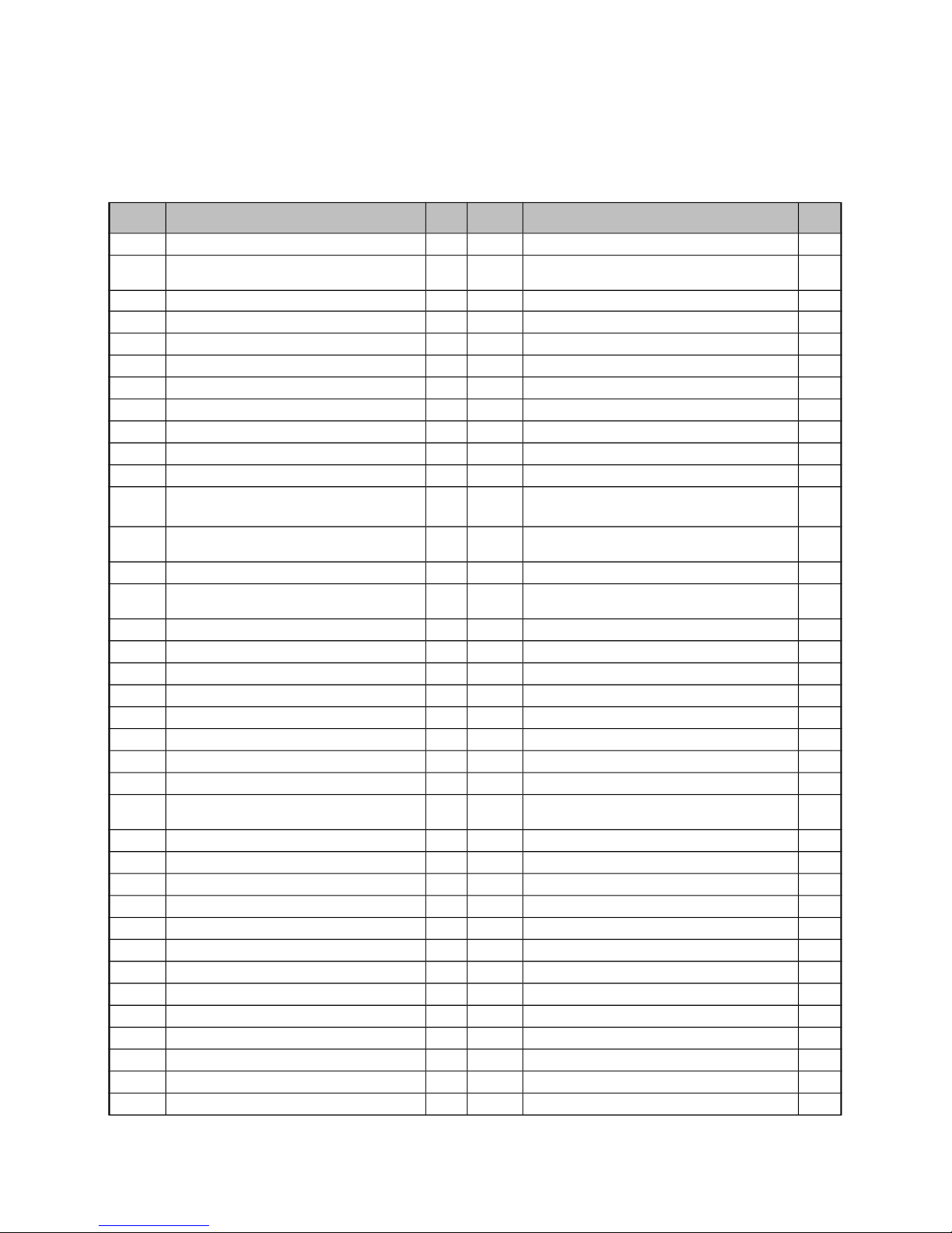
PARTS LIST
No. Description
Qty
No. Description
Qty
1 Main Frame 1 39 Hexagon Bolt M8×20 1
2 Handlebar 1 40
Cros s Pan Hea d Tapping screw
ST4.2×25
7
3 Meter Post 1 41 Tension Spring Φ20×39×δ3.2 1
4 Rear Stablizer 1 42 Nylon Nut M8 4
5 Magnetic Wheel Φ180×25 1 43 Hexagon Bolt M6×20 1
6 Front Stabilizer Φ50×1.5 1 44 Pressure Plate 1
7 Tension Control Knob 1 45 Bearing 6000Z 2
8
Seat Height Adjustment Knob M16
1 46 Arc WasherΦ5 1
9 Belt 290/J4 1 47 Bushing Ф21×Ф15.2×3.0 1
10 Meter 1 48 Flat Washer Φ40×2.8 1
11 Magnetic bracket 1 49 End Cap for Handlebar 2
12 Seat Post Plastic Bushing 1 50
Handrail Arm Foam Grip
Φ21×Φ27×500
2
13 Left Chain Cover 1 51
Cross Pa n H ead Tapping Screw
ST4.2×20
2
14 Spring 65Mn/Φ10×50vδ1.0 1 52 Circlip Φ10 1
15
Cross Pan Head Tapping Screw
ST2.9×9.5
2 53 Hand Pulse Sensor 2
16 Flat Washer Φ23×Φ35×2.0 1 54 Tension Cable 1
17 Puller Bushing (7/8)" 1 55 Hexagon Bolt M6 1
18 Hexagon Bolt 1 56 Flat Washer Φ5 2
19 Belt Pulley with Crank 6" 1 57 Cross Pan Head Bolt M5×45 1
20 Left Foot Pedal (1/2)" 1 58 Puller Bushing (15/16)" 1
21 Right Foot Pedal (1/2)" 1 59 ExtensionSensor Wire L=750mm 1
22 Bearing Bush Φ55.6×16 2 60 Crank Cover 2
23 Bearing Φ44.5 2 61 Right Chain Cover 1
24 Hexagon Bolt M8×15 4 62
Cross Pan Head self-drilling Screw
ST4.2×25
4
25 Seat Post 1 63 Cross Pan Head Bolt M5×10 2
26 Sensor L=350mm 1 64 Decorative cover for Handlebar 1
27 Seat Cushion 1 65 sleeve 1
28 End Cap for Front Stabilizer 2 66 T-Shape Knob 1
29 End Cap for Rear stabilizer 2 67 Seat Slide Tube 1
30 Magnetic Wheel Axle Φ17×90 1 68 Plug for square tube 2
31 Bearing 6203Z 2 69 Cover for seat slide tube 1
32 Curve Washer Φ17 1 70 Pan Head Bolts 1
33 Nylon Nut M6 1 71 Square fixer 1
34 Cap Nut M10 4 72 Seat slide Tube Knob 1
35 Bolt M10×57 4 73 Flat washer 1
36 Arc Washer Φ10 4 74 Plug for wire 1
37 Arc Washer Φ8 4 75 Decorative cover for Meter post 1
3
Page 3
38 Flat Washer Φ8 3 76 Decorative cover for Seat post 1
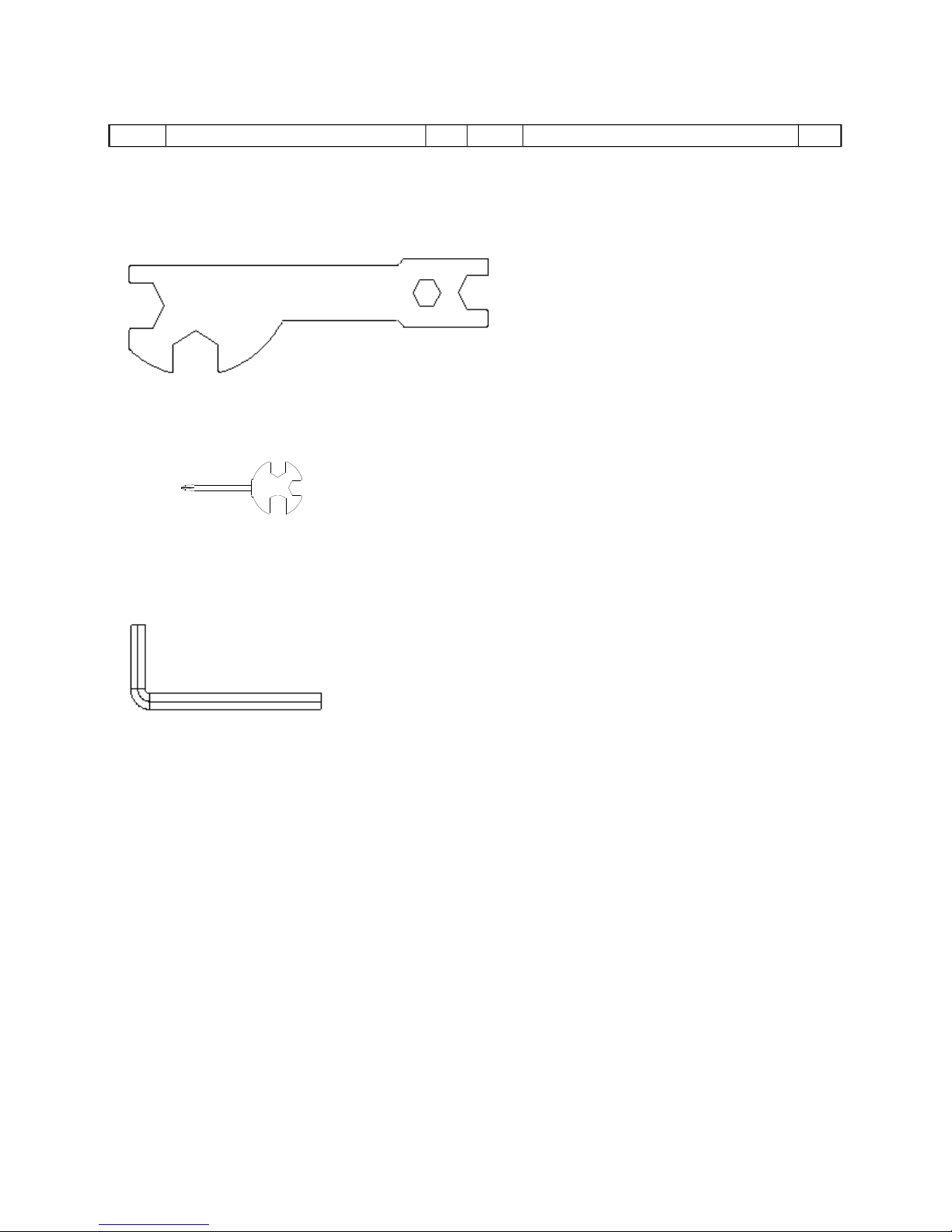
TOOLS
Multi Hex Tool S19-S10- S13- S17
Multi Hex Tool with Phillips Screwdriver
S13-S14-S15
Allen Wrench S6
4
Page 4
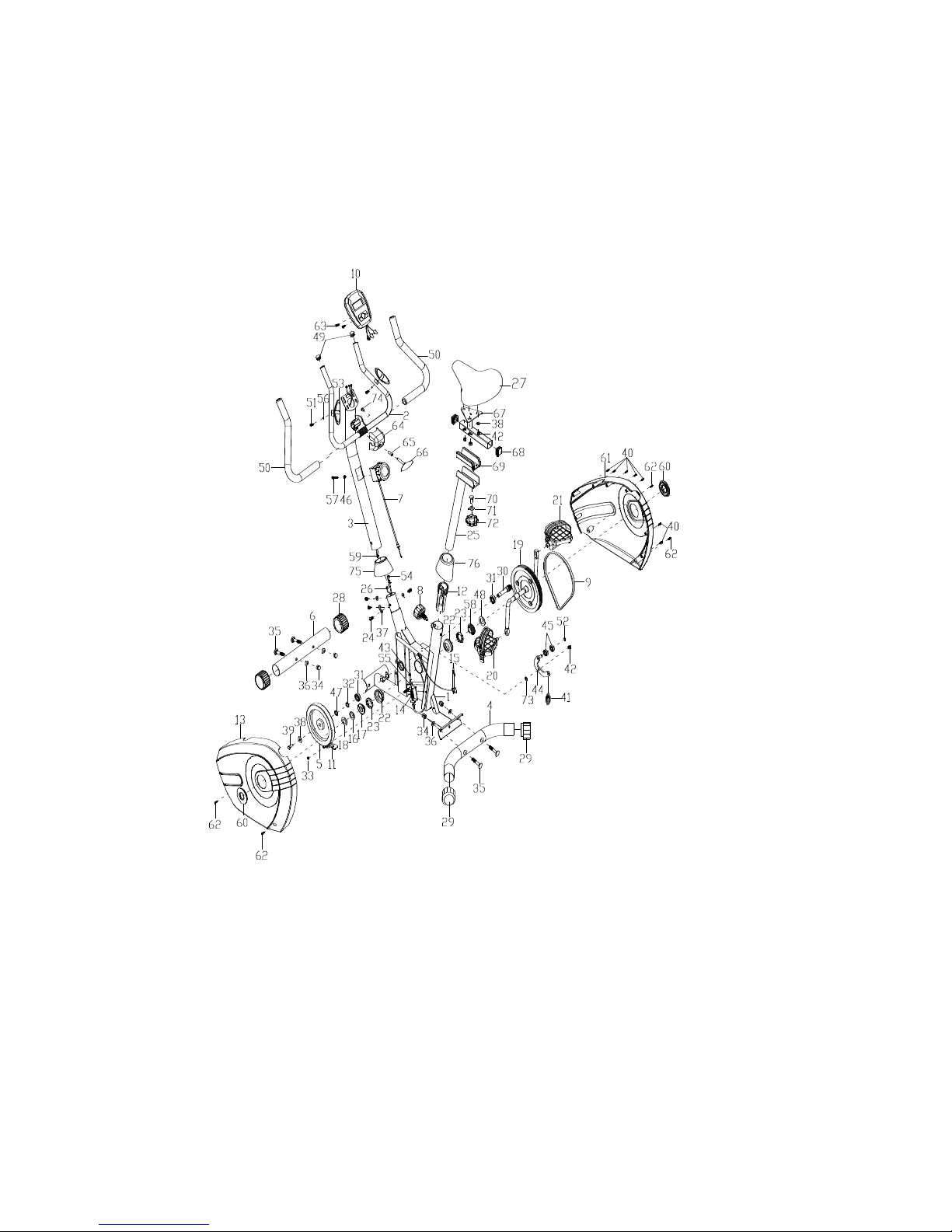
EXPLODED DRAWING
ASSEMBLY INSTRUCTION
5
Page 5
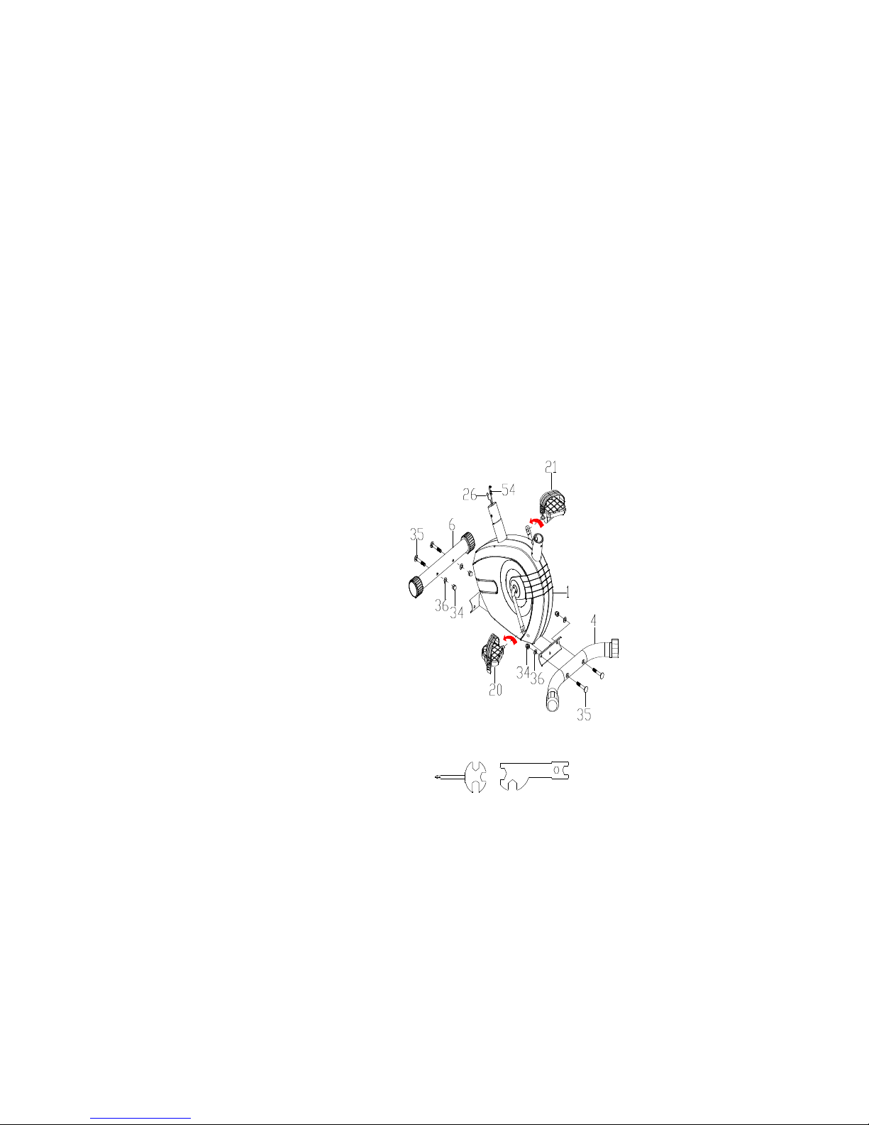
1. Front and Rear Stabilizers Installation
Attach the Front Stabilizer (6) and Rear Stablizer(4) onto the front curve of the Main
Frame (1) with four M10 x 57 Bolts (35), four Φ10 Arc Washers (36) and four M10 Cap
Nuts (34). Tighten cap nuts with the Multi Hex Tool provided.
2. Left and Right Foot Pedals Installation
The Cranks, Pedal Shafts, and Foot Pedals are marked “R” for Right and “L” for Left.
Insert pedal shaft of Left Foot Pedal (20) into threaded hole in the left crank. Turn the pedal
shaft by hand in counter-clockwise direction until snug.
Note: DO NOT turn the pedal shaft in the clockwise direction, doing so will strip the threads.
Tighten the pedal shaft of Left Foot Pedal (20) with the Multi Hex Tool with Phillips
Screwdriver provided.
Insert pedal shaft of Right Foot Pedal (21) into threaded hole in right crank. Turn the pedal
shaft by hand in clockwise direction until snug. Tighten the pedal shaft of Right Foot Pedal
(21) with the Multi Hex Tool with Phillips Screwdriver provided.
3. Meter Post Installation
Remove four M8x15 Hexagon Bolts (24) and four Φ8 Curve Washers (37) from the tube of
Main Frame (1). Remove bolts with S6 Allen Wrench provided.
Insert the Meter Post(3) into the Cover for meter post(75)
6
Tool:
Multi Hex Tool with Phillips Screwdriver
Multi Hex Tool S19, S10, S13, S17
Page 6
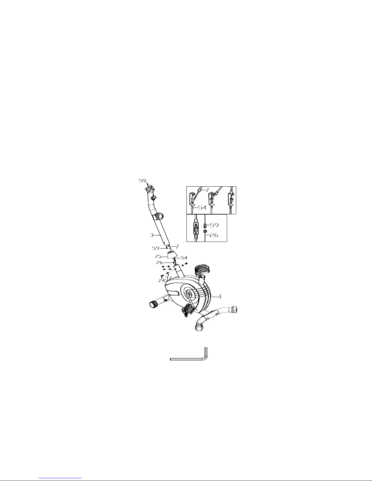
Connect the Sensor Wire (26) from the Main Frame (1) to the Extension Sensor Wire (59)
from the Handlebar Post (3).
Put the Cable end of resistance cable of Tension Control Knob (7) into the cable lock of
Tension Cable (54). Pull the resistance cable of Tension Control Knob (7) up and force it into
the slot of metal bracket of Tension Cable (54). Insert the metal fitting on the resistance cable
of Tension Control Knob (7) into the hole at the end of slot in the metal bracket of Tension
Cable (54).
Connect the resistance cable of Tension Control Knob (7) to Tension Cable (54) complete.
Insert the Handlebar Post (3) onto the tube of Main Frame (1) and secure with four M8x15
Hexagon Bolts (24) and four Φ8 Curve Washers (37) that were removed. Tighten bolts with S6
Allen Wrench provided.
4. Seat Cushion, Seat Post Bellows, Seat Post Installation
Remove three Washers (38) and three M8 Nylon Nuts (42) from underside of the
Seat Cushion (27). Guide bolts on underside of the Seat Cushion (27) through holes on
7
Tool:
Allen Wrench S6
Page 7
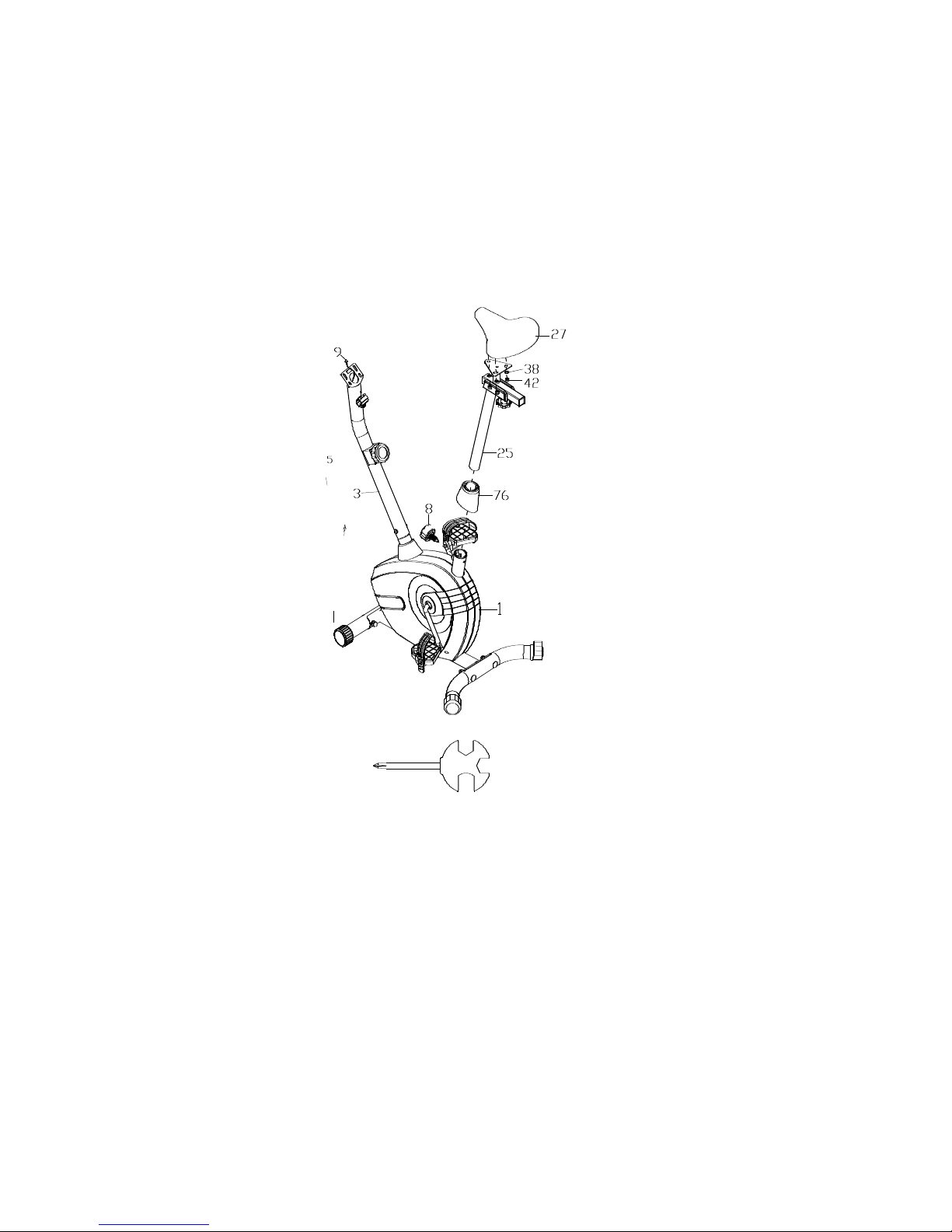
top of the Seat Post(25), attach with three removed Washers (38) and Nylon Nuts (42).
Tighten nylon nuts with the Multi Hex Tool provided. Then secure the Seat Post(25) with
Frame(1) with the Knob(8)
5. Handlebar Installation
Insert the two wire of from Handlebar into the hole of Meter Post(3),and let the two wire come
out from top of Meter Post
8
Tool:
Multi Hex Tool with Phillips Screwdriver
Page 8
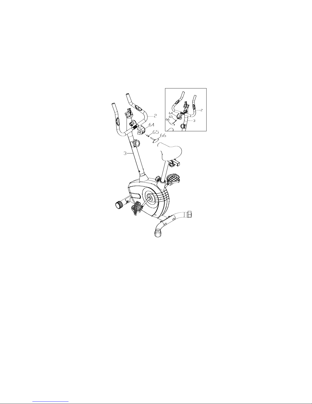
Attach the Handlebar(2) onto the Meter Post(3) with T-Shape Bolt(66),Sleeve(65)and
Decorative cover for Handlebar(64)
6. Meter Installation
9
Page 9
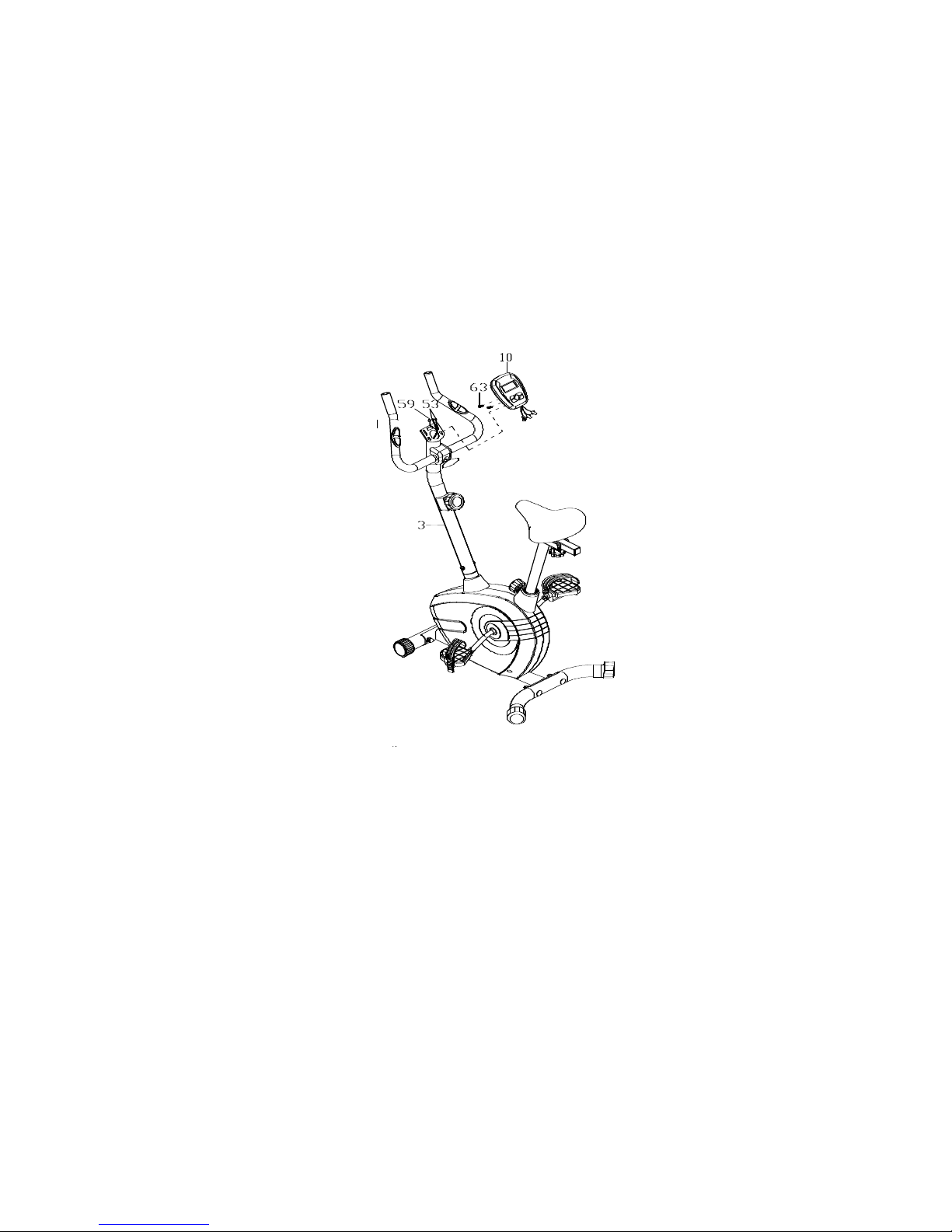
Remove two bolts (63) from back of Meter(10), connet the three wires from Meter(10)to the
three wires from the top of meter post(3). Then secure the meter(10) to the meter post(3) with
Bolts(63)
10
Tool:
Multi Hex Tool with Phillips Screwdriver
Page 10
MAINTENANCE
Cleaning
The bike can be cleaned with a soft clean damp cloth. Do not use abrasives or solvents on
plastic parts. Please wipe your perspiration off the x bike after each use. Be careful not
get excessive moisture on the computer display panel as this might cause an electrical
hazard or electronics to fail.
Please keep the bike, especially the computer console out of direct sunlight to prevent
screen damage.
Please inspect all assembly bolts and pedals on the machine for proper tightness every
week.
Storage
Store the x bike in a clean and dry environment away from children.
TROUBLESHOOTING
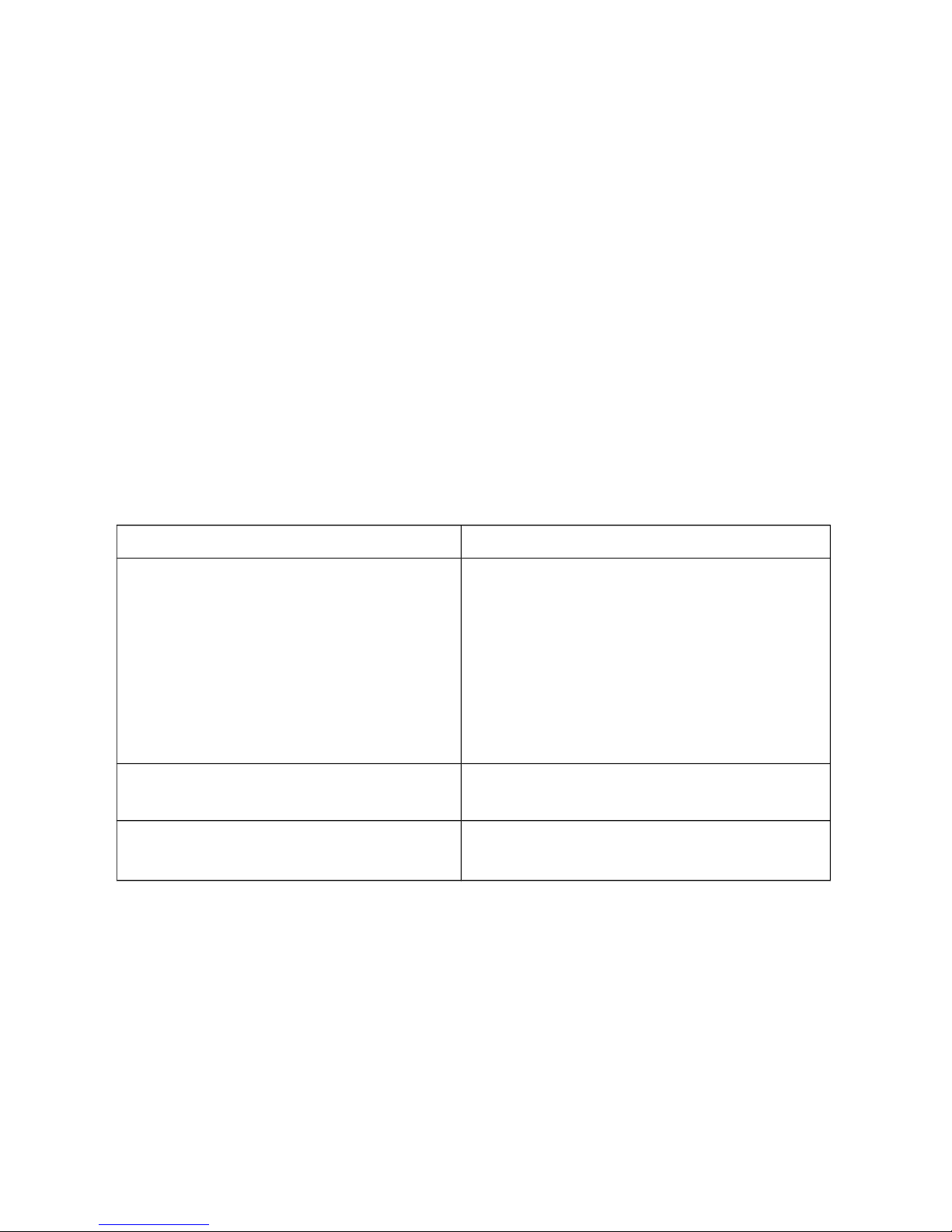
PROBLEM SOLUTION
There is no display on the computer
console.
1. Remove the computer console and verify
the wire that comes from the computer
console is properly connected to the wire
that comes from the handlebar post.
2. Check if the batteries are correctly
positioned and battery springs are in
proper contact with batteries.
3. The batteries in the computer console may
be dead. Change to new batteries.
The bike wobbles when in use Turn the rear stabilizer end cap on the rear
stabilizer as needed to level the bike.
The bike makes squeaking noise when in
use.
The bolts may be loosen on the bike. Please
inspect all of the bolts and tighten any loosen
bolts.
EXERCISE MONITOR INSTRUCTION MANUAL
11
Page 11

SPECIFICATIONS
TIME--------------------------------------------------0:00~99:59MIN
SPEED------------------------------------------------0.0~999.9ML/H (KM/H)
DISTRANCE----------------------------------------0.00~999.9ML (KM)
CALORIE--------------------------------------------0.0~999.9KCAL
ODO(IF HAVE) ------------------------ 0.0~99.99ML (KM)
PULSE (IF HAVE) ---------------------------------40~240BPM
KEY FUNCTIONS:
MODE: This key lets you to select and lock on to a particular function you want.
The key to reset the value to zero by pressing the key for 4 seconds.
FUNCTIONS:
TIME : Press the MODE key until pointer lock in to TIME. The total working time will be
shown when starting exercise.
SPEED: Press the MODE key until pointer lock on to REPS/MIN Display current speed
during working time
DISTANCE : Press the MODE key until pointer lock on to DISTANCE . The distance of each
workout will be displayed when starting exercise.
CALORIE :Press the MODE key until pointer lock on to CALORIE The calorie burned will be
displayed when starting exercise.
5.ODO :(IF HAVE) Automatically accumulates workout distance when starting exercise.
6.PULSE(IF HAVE): Press the MODE key until the pointer advance to PULSE function
and put ear-clip to ear or the hand take hole of the sensor about 3 seconds show out.
SCAN : Display changes according to the next diagram every 4 seconds.
Automatically display of the following functions in the order shown: TIME---SPEED--DISTANCE---CALORIE---ODO (IF HAVE) ---PULSE (IF HAVE)---SCAN
NOTE:
Without any signal coming in 4-5 minutes , the LCD display will be shut off automatically.
When there is signal input ,the monitor automatically turns on.,
If there is a possibility to see an improper display on the monitor, please replace the batteries
to have a good result .You must be to replace the batteries at the same time.
4.The monitor use 2pcs of 1.5v“AAA”batteries.
12
Page 12
GARLANDO SPA
Via Regione Piemonte, 32 - Zona Industriale D1
15068 - Pozzolo Formigaro (AL) - Italy
www.toorx.it - [email protected]
 Loading...