


Edizione : Revisione : 00
INSTRUCTION
08/16 00

1
Dear Customers,
We want to thank you for having chosen a Magnetic Bike and wish
you a lot of fun and success during training.
Please note and follow the enclosed safety and assembly instructions
carefully.
If you have questions please do not hesitate to contact us.
Table of Content as blew:
1.) Safety Instruction
2.) Exploded Drawing
3.) Parts List
4.) Assembly Instruction
5.) Computer Instruction
4
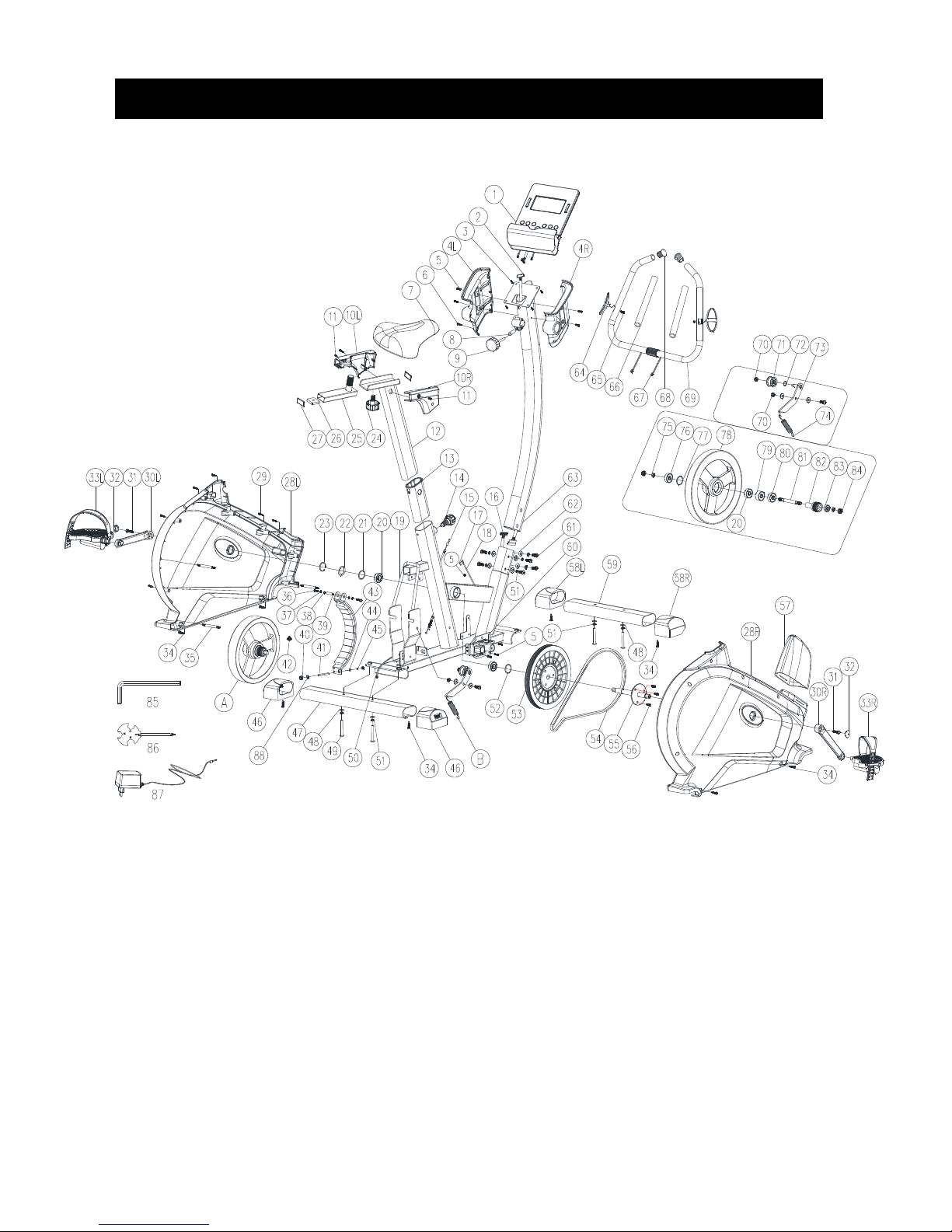
EXPLODED DRAWING
B
A

5
PART LIST
Part #
Description
Quantity
1
Computer
1
2
Upper computer cable
1
3
Screw 4 4L
Computer plastic cover (Left)
1
4R
Computer plastic cover (Right)
1
5
Screw
8
6
Self-tapping screw
2
7
Saddle 1 8
Tube spacer
1
9
Round-shaped Knob
1
10R
Seat post plastic cover (Left)
1
10L
Seat post plastic cover (Right)
1
11
Screw 2 12
Seat post
1
13
Tube bundle
1
14
Round head grooved pin
1
15
Tension cable
1
16
Lower computer cable
1
17
Sensor set
1
18
Sensor 1 19
Main frame
1
20
Bearing 3 21
Washer 1 22
Waved washer
1
23
C shape washer
1
24
Round head grooved pin
1
25
Slide tube
1
26
Nut
1
27
Tube end cap
2
28L
Chain cover (Left)
1
28R
Chain cover (Right)
1

6
Part #
Description
Quantity
29
Self-tapping screw
6
30L
Crank (Left)
1
30R
Crank (Right)
1
31
Anti-loose hex head bolt
2
32
Crank end cap
2
33L
Pedal (Left)
1
33R
Pedal (Right)
1
34
Screw 8 35
Joint lever
3
36
Hex screw
2
37
Spring washer
2
38
Washer 2 39
Axle for flywheel holder
1
40
Nut
2
41
Hex screw
1
42
Tapered spring
1
43
Manget set
1
44
Washer 1 45
Washer 1 46
Rear end cap
2
47
Rear Stabilizer
1
48
Flat washer
10
49
Allen bolt
4
50
DC line
1
51
Spring washer
10
52
Washer
1
53
Belt wheel
1
54
Belt 1 55
Pedal Axle
1
56
Allen head screw
3
57
Upper protective cover
1
58L
Front end cap Left
1
58R
Front end cap Right
1

7
Part #
Description
Quantity
59
Front Stabilizer
1
60
Motor
1
61
Allen bolt
7
62
Curved washer
2
63
Handlebar post
1
64
Hand pulse pads
2
65
Self-tapping screw
2
66
Handlebar foam
2
67
Hand pulse cable
2
68
End cap 2 69
Handlebar
1
70
Nut 2 71
Idler 1 72
Waved washer
1
73
Idler rack
1
74
Spring
1
75
Spring
2
76
Bearing 1 77
Washer 1 78
Flywheel 1 79
Oneway bearing
1
80
Bearing 1 81
Axle for flywheel
1
82
Small belt wheel
1
83
Bearing
1
84
Nut
2
85
Allen key wrench
1
86
Combination wrench
1
87
Adaptor
1

8
ASSEMBLY INSTRUCTION
STEP 1
Attach the Front Stabilizer (59) onto the Main Frame (19) with Flat washer
(48), Spring washer (51) and M8 Allen bolt (49).Tighten fully.
Attach the Rear Stabilizer (47) onto the Main Frame (19) with Flat washer
(48), Spring washer (51) and M8 Allen bolt (49).Tighten fully.
Note:You can adjust the Rear End Cap to keep the Magnetic Bike stable.

9
STEP 2
Pull out the Upper protective cover (57) from the Main frame (19) and
attach it to the Handlebar post (63) shown as right image
Connect the Upper Computer Cable (2) with Lower Computer Cable (16)
shown as the left top image.
Attach the Handlebar Post (63) onto the Main Frame (19) with M8 Allen
Bolts (61), Spring Washers (51), Flat washer (48) or Curved Washers (62).
Tighten fully. Then slide down the Upper protective cover (57).

10
STEP 3
Assemble the saddle (7) to the adjustable Seat post (12) by the nut shown
as the left image.
Place the Seat Post (12) into the Main Frame (19), set it at the desired
position and lock it by inserting Round head grooved pin (14) in place and
tighten fully.
The setting of the seat post can be adjusted up and down easily as
desired later through turning and pulling the Round head grooved pin (14).
The user could adjust the saddle backward and frontward as well by
adjusting the knob (24). See the right images.

11
STEP 4
Assemble the pedals Left and Right (33L) & (33R) to the crank Left and
Right (30L) & (30R).
Attach the Handlebar (69) onto the Handlebar Post (63) with Tube Spacer
(8) and Round-shaped Knob (9).Tighten fully.
Remember to pull the Hand pulse cable (67) through the hole above
Handlebar holder plate (63) and extent to the upright position, see the right
image.

12
STEP 5
Remove the screws (3) from the back of the computer (1).
Connect the Upper Computer Cable (2) with the Computer (1).
Connect the Hand pulse cables (67) with the Computer (1).
Attach the Computer (1) onto the computer bracket with 4 M5 screws (3).

13
STEP 6
Attach the left and right Computer Plastic Cover (4L+4R) onto the
Handlebar with and M4 Screws (6) and M5 Screws (5).
Now your machine is ready for use.

14
COMPUTER INSTRUCTION
BUTTON FUNCTION:
MODE/ENTER
In stop mode, the mode is to confirm all exercise data setting, and enter into program.
RESET
In stop mode, press the button back to main menu.
START/STOP
To start or stop exercise.
RECOVERY
To test hear rate recovery status.
UP
To select training mode and adjust function value up.
DOWN
To select training mode and adjust function value down.
BODY FAT
For body fat measurement
DISPLAY EXERCISE DATA:
TIME
Display range 0:00~99:99 ; Setting range 0:00~99:00
DISTANCE
Display range 0.00~99.99 ; Setting range 0.00~99.90km
CALORIES
Display range 0~9999 ; Setting range 0~9990
PULSE
Display range P-30~230 ; Setting range 0-30~230
WATT
Display range 0~999 ; Setting range 10~350
SPEED
0.0~99.9km
RPM
0~999

15
OPERATION PROCEDURE
1. Connect power supply and computer will power on with a long beep sound, LCD display all
segments (drawing A) for 2 seconds and enter into personal data setting mode (gender, age, height
and weight) for U1~U4. (drawing B~C)
2. After user data set up, computer will display main menu (drawing D).
A B
C D
3. In main menu, first exercise program MANUAL will flash, user may press UP and DOWN button
to select MANUAL PROGRAM (12 profiles) (drawing E) USER PROGRAMHRC
(drawing F)WATT.
E F
4. Quick Start and Manual :
Before exercise in Manual mode, user my set up TIME, DISTANCE, CALORIES and PULSE
target.

16
After power on, user may press START/STOP button to start exercise in MANUAL immediately
without any setting.
Level can be adjusted during exercise by press UP or DOWN.
5. PROGRAM:
Before exercise in Program mode, user may set up TIME target.
Press UP and DOWN to select Program with 12 profiles and press ENTER/MODE to confirm.
Level can be adjusted during exercise by press UP or DOWN.
6. H.R.C.:
Select the H.R.C. mode and press the MODE key to enter into the setting mode. AGE
default value is 25 (years old). There will be 4 selections: H.R.C55, H.R.C.75, H.R.C.90
and H.R.C. TAG; use the UP/ DOWN key to select one program and press the MODE
key after selection is determined (FIGURE G & H). User’s selection and a sign of “55%”
will be displayed in the PULSE column according to the AGE user inserted. If user selects
H.R.C. TAG (press the MODE key to enter), preset PULSE value “100” will be shown in
flashing text and user can press the UP/ DOWN key to adjust target range from 30~230.
G H
7. USER PROGRAM:
User may press UP, DOWN and then press MODE to create his own profile. (from column 1 to
column 20) User may hold on pressing MODE button for 2 seconds to quit profile setting.
8. WATT :
The preset watt value 120 is flashing on screen in WATT setting mode. User may use UP,
DOWN button to set target value from 10 to 350. Press MODE button for confirm.
9. BODY FAT:
9-1 In STOP mode, press the BODY FAT button to start body fat measurement.
9-2 Then selected user (U1~U4) will blinking for 2 seconds. Then start measuring.
9-3 During measuring, user have to hold both hands on the handgrip. And the LCD will display “-
-” “--“ for 8 seconds until computer finish measuring.
9-4 LCD will display BODY FAT advice symbol, BODY FAT percentage, BMI for 30 seconds.

17
10. RECOVERY :
After exercising for a period of time, keep holding on handgrips and press “RECOVERY”
button. All function display will stop except “TIME” starts counting down from 00:60 to 00:00.
Screen will display your heart rate recovery status with the F1,F2….to F6. F1 is the best, F6
F6 is the worst. User may keep exercising to improve the heart rate recovery status.
(Press the RECOVERY button again to return the main display.)
NOTE:
1. This computer require 9V, 500mA adaptor.
2. When user stop pedaling for 4 minutes, computer will enter into power save mode, all setting and
exercise data will stored until user start exercise again.
3. When computer act abnormal, please plug out the adaptor and plug in again.

GARLANDO SPA
Via Regione Piemonte, 32 - Zona Industriale D1
15068 - Pozzolo Formigaro (AL) - Italy
www.toorx.it - info@toorx.it
 Loading...