

Page 1
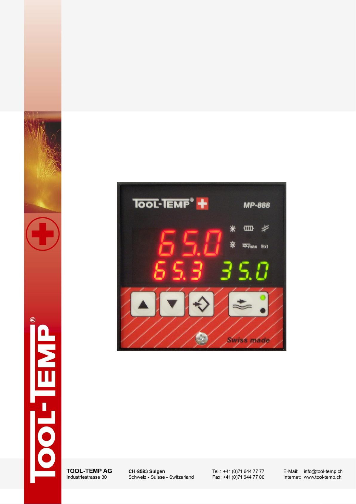
software-version C30
06/2014
Version: 14
Guidance - Supplement to the manual of instructions
Microprocessor
Temperature Controller MP-888
Page 2
Guidance MP-888 - Supplement to the manual of instructions 2/10
HINWEIS
This guidance provides specific information to the temperature controller.
Observe the General Safety Information in the manual of instructions to the
TOOL-TEMP machine!
General information
This documentation is copyrighted. Unauthorised duplication is prohibited by law. To the best of our
knowledge and belief, the information contained in this documentation is true and correct as of the
date of publication. The contents, however, do not constitute a binding obligation on the part of
TOOL-TEMP AG and are subject to change without notice.
In case of inconsistencies in the English translation, the German version shall prevail.
© Copyright 2013 TOOL-TEMP AG
Contents
1. Overview MP-888 ........................................................................................................................... 3
2. Overview controller programmes ................................................................................................ 5
3. Selection of the controller programme ....................................................................................... 7
4. Navigation in the controller .......................................................................................................... 7
5. Parameter – Overview ................................................................................................................... 8
Page 3
Guidance MP-888 - Supplement to the manual of instructions 3/10
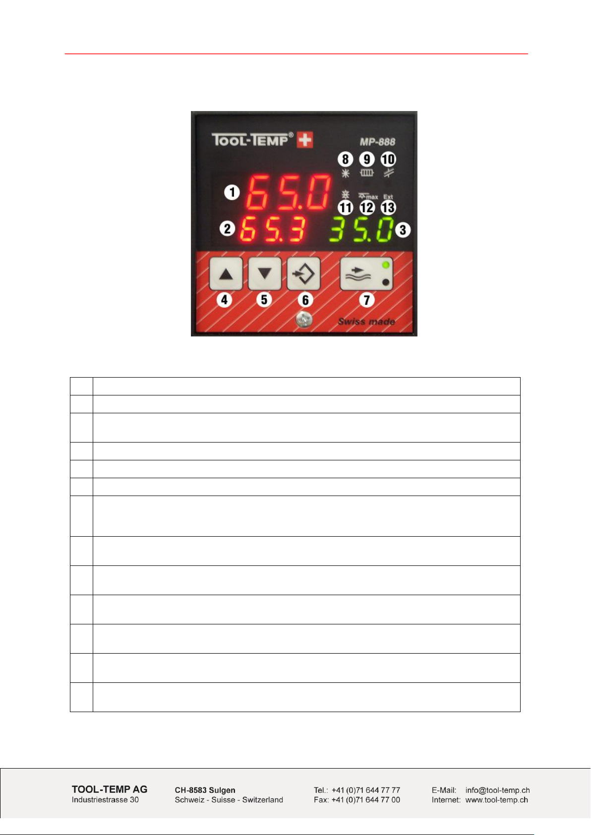
1
Display of set value
2
Display of actual value
3
Flow control
Display of the current flow in litres/min, English or American gallons/min.
4
Up arrow Raise of set value
5
Down arrow Reduction of set value
6
Program button
7
Flow control
Flow control active LED green
Alarm flow control LED red
8
LED Cooling
Lights up when the cooling relay is activated
9
LED Heating
Lights up when the heating relay is activated
10
LED Sensor failure
Lights up when the sensor is intermitted
11
LED Temperature deviation control
Lights up when the difference between set and actual temperature is too high
12
LED Maximum temperature
Lights up when the maximum temperature has been reached
13
LED External temperature control
Lights up when the set value is applied from extern
1. Overview MP-888
Page 4

Guidance MP-888 - Supplement to the manual of instructions 4/10
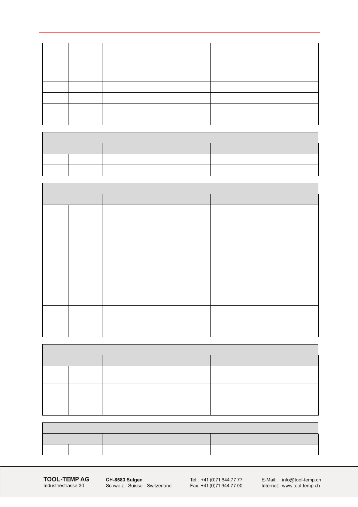
1
Possible supply voltages (factory adjusted)
2
Possible temperature sensor (factory adjusted)
3
Version of the controller
4
Temperature sensor connection
21+23 Temperature sensor – note + / 22 Pt-100 compensation
5
Flow control – encoder signal
6
Connection external set point
26+28 Analog input 4- 20mA
27+28 Analog input 0 - 10 V
7
Connection actual value - output
29+30 Analog output 0 - 10V
8
Power supply
1 230V AC
2 Neutral
3 PE
9
Flow control (alarm)
10
Temperature monitoring, temperature deviation alarm
11
Cooling (command)
12
Heating (command)
Page 5

Guidance MP-888 - Supplement to the manual of instructions 5/10
Temperature Control Units without flow control
Programme
New models
Old models
P 41
P US 41
TT-180, TT-181
TT-155, TT-156, TT-157 E, TT-162 E,
TT-162H
P 42
P US 42
TT-170 L, TT-100 K-E, TT-100 KB-E
TT-162 E/PHE, TT-162 H/PHE,
TT-162 E/A, TT-162 H/A, TT-154 E,
TT-113 K, TT-103 K FeKo
P 43
P US 43
TT-130, TT-131, TT-132, TT-133,
TT-134, TT-139
P 44
P US 44
TT-220, TT-230, TT-240, TT-245
P 45
P US 45
TT-260, TT-270, TT-280, TT-280/2
P 46
P US 46
TT-360, TT-370, TT-380, TT-380/2,
TT-380 / 48 kW
P 47
P US 47
TT-300, TT-301, TT-302, TT-303,
TT-304, TT-305, TT-500, TT-700
Temperature Control Units with flow control
Programme
New models
Old models
P 72
P US 72
TT-DW160 9kW
P 73
P US 73
TT-1358
P 74
P US 74
TT-1398
TT-148
P 75
P US 75
TT-108 E / 6 - 18 kW / Pt-100
P 76
P US 76
TT-108 K / 18 - 45 kW / Pt-100
P 77
P US 77
TT-1000
P 78
P US 78
TT-137 B/BP, TT-138 B/BP
P 79
P US 79
TT-188, TT-168 E special unit
1,5 – 35 l/min
P 80
P US 80
TT-188, TT-168 E, TT-168 H
P 81
P US 81
TT-168 E/A, TT-168 H/A,
TT-168 E/PHE, TT-168 H/PHE,
TT-168 E/A/PHE, TT-168 H/A/PHE
P 82
P US 82
TT-118 K, TT-1038 K, TT-108 K FeKo
P 83
P US 83
TT-1548 E
P 84
P US 84
TT-137 N-B, TT-138 N-B,
TT-142 N-B, TT-142 B/BP
TT-143
P 85
P US 85
TT-288, TT-288/2
P 86
P US 86
TT-1368
P 87
P US 87
TT-388, TT-388/2, TT-390, TT-390/2
2. Overview controller programmes
Once the „US-programs“ are set, the corresponding parameters are adjusted automatically on USGallons per minute and degree Fahrenheit.
Page 6
Guidance MP-888 - Supplement to the manual of instructions 6/10
P 88
P US 88
TT-388 / 48 kW, TT-608 Z
TT-380 / 48 kW with flow control
P 89
P US 89
TT-508 X, TT-510 X
TT-500 with flow control
P 90
P US 90
TT-708 Y
TT-700 with flow control
P 91
P US 91
TT-248
P 92
P US 92
TT-407 Z, TT-409 Z
TT-408
P 93
P US 93
TT-410 X
P 94
P US 94
TT-30/160
Heating- and cooling unit:
Programme
New models
Old models
P 09
P US 09
TT-13‘502 10 - 90°C
P 10
P US 10
TT-13‘502 10 - 40°C
Water chillers without flow control
Programme
New models
Old models
P 11
P US 11
TT-29‘000, TT-54‘000, TT-54‘000 WK,
TT-54‘000 OT, TT-108‘000,
TT-108‘000 WK, TT-108‘000 OT,
TT-216‘000, TT-216‘000 WK,
TT-216‘000 OT, TT-14‘000 E/LC
TT-4‘500, TT-5‘000, TT-9‘500,
TT-11‘000, TT-11‘000 WK,
TT-12‘000, TT-12‘000 WK,
TT-14‘000, TT-14‘000 WK,
TT-20‘000, TT-23‘000,
TT-23‘000 WK, TT-25‘000,
TT-28‘000, TT-28‘000 WK,
TT-29‘000 WK, TT-40‘000,
TT-41‘000, TT-57‘000,
TT-57‘000 WK, TT-70‘000,
TT-80‘000, TT-80‘000 WK,
TT-95‘000, TT-95‘000 WK,
TT-110‘000, TT-110‘000 WK,
TT-160‘000, TT-160‘000 WK
P 12
P US 12
TT-5‘000 H, TT-14‘000 H,
TT-28‘000 H, TT-5‘000 E/LC
TT-4‘500 H, TT-9‘500 H,
TT-11‘000 H, TT-12‘000 H ,
TT-14‘000 H, TT-20‘000 H,
TT-23‘000 H, TT-25‘000 H
Water chillers with flow control
Programme
New models
Old models
P 13
P US 13
TT-5‘500 E, TT-14‘500 H,
TT-14‘500 H/WK
P 14
P US 14
TT-28‘500, TT-28‘500 WK,
TT-28‘500 OT, TT-29‘500 WK,
TT-54’500, TT-54’500 WK,
TT-54‘500 OT, TT-58‘500 WK
For all units with a special programming
Programme
New models
Old models
P 100
Special programming
Page 7

Guidance MP-888 - Supplement to the manual of instructions 7/10
By starting the controller, the software-version is first shown (C-30) and afterwards the programme
number (P80).
Each temperature control unit or water chiller requires a different programming of the parameters.
The different parameters adjustments are saved in each program.
Start the unit, on the display follows…
up: Software-version (C30)
down left: Temperature unit in °C
down right: Flow unit in liters per minute
P80 Software-version
Press button twice
With the arrow buttons choose the required programme
(see overview controller programmes)
Press button once to save
4. Navigation in the controller
Enter into the controller and navigate to the different parameter:
To enter into the programme of the controller, the program button has to be pressed
for 3 seconds.
To move from parameter to parameter, press the programme button.
Setting the parameter value:
With the two arrow buttons the value of the parameters can be adjusted.
Save the parameter settings:
To save the parameter settings and get back to the control function, the flow button
must be pressed.
To save the parameter settings and move to the next parameter, the programme
button must be pressed.
For all units with special programming P100:
If a parameter will be changed the controller shows P100. Controllers with a
special programing have a written the parameters on a label on the
controller and in the manual of the model.
3. Selection of the controller programme
Page 8

Guidance MP-888 - Supplement to the manual of instructions 8/10
Function
Factory adjusted
User
Agent
TOOL-TEMP
Description
P1
Maximum
temperature
Setting depends
on model
(0.0...400.0°C)
(32.0...752.0°F)
If the maximum temperature exceeds,
the heating and cooling are inactive and
the maximum temperature LED lights up
on the controller.
P2
Temperature
deviation control
(Deviation between
set and actual
temperature)
5.0°C / 9.0°F
(0…20.0°C)
(0…36.0°F)
The limit determines the maximum
deviation from the nominal value, which
is still tolerated. If the actual temperature
outside the set point window the alarm
will sound and the Temperature
deviation control LED lights. If the restart
lock (P24) is turned on, the temperature
deviation control is active only when it
reaches the set temperature. A set point
changes the start-up lock again.
P3
Flow measurement
function
0: Manuel
1: Automatic
If the automatic flow measurement is
enabled, after 20s the measured flow is
stored and monitoring is enabled. The
green LED lights up.
P4
Alarm value flow
8.0 L
(0.1…999.9 L)
(P3) set to manual
Alarm is triggered when the set value is
exceeded.
P20
Temperature unit
1: °C
2: °F
Change the temperature unit:
When the unit started the selected unit
will be indicated for a short time.
P21
Temperature sensor
Setting depends
on model
1: Fe-Ko J
2: NiCr-Ni K
3: Pt 100 2-Draht
4: Pt 100 3-Draht
Selection of temperature sensor
P22
Temperature
adjustment on Pt 100
0.7°C / 33.3°F
(0.0...130.0°C)
(0.0...234.0°F)
When using very long sensor lines
(Pt 100) the resistor of the line can be
compensated. A compare measurement
is needed. For example:
measured temperature: 100°C
indicated temperature: 108°C.
-> set 8°C (difference)
P23
Analog input
1: Voltage 0-10V
2: Current 0-20 mA
3: Current 4-20 mA
Analog input for setpoint selection.
0-10 V (switching threshold <0.1V)
0-20 mA (switching threshold <0.5mA)
4-20 mA (switching threshold <0.1mA)
P24
Starting interlock for
temperature deviation
control
0: OFF
1: ON
see P2
5. Parameter – Overview
Page 9

Guidance MP-888 - Supplement to the manual of instructions 9/10
P25
Setting range FROM
Setting depends
on model
(-50.0...399.0°C)
(-58.0...750.2°F)
This temperature value limits the lowest
temperature that can be adjusted.
P26
Setting range TO
Setting depends
on model
(-49.9...400.0°C)
(-57.8...752.0°F)
This temperature value limits the highest
temperature that can be adjusted.
P27
Temperature
at 0 V INPUT
0.0°C / 32°F
(-50.0...399.9°C)
(-58.0...751.8°F)
Lower scaling point of the voltage
analog input
0 V corresponds to 0°C
P28
Temperature
at 0 V INPUT
400.0°C / 752°F
(-49.9…400.0°C)
(-57.8…752.0°F)
Upper scaling point of the voltage
analog input
10 V corresponds to 400°C
P29
Temperature
at 0/4 mA INPUT
0.0°C / 32°F
(-50.0...399.9°C)
(-58.0...751.8°F)
Lower scaling point of the voltage
analog input
4 mA corresponds to 0°C
P30
Temperature
at 20 mA INPUT
400.0°C / 752°F
(-49.9…400.0°C)
(-57.8…752.0°F)
Upper scaling point of the voltage
analog input
20 mA corresponds to 400°C
P31
Temperature
at 0 V OUTPUT
0.0°C / 32.0°F
(-50.0…399.9°C)
(-58.0…751.8°F)
Lower scaling point of the voltage
analog output
0 V corresponds to 0°C
P32
Temperature
at 10 V OUTPUT
400.0°C / 752°F
(-49.9…400.0°C)
(-57.8…752.0°F)
Upper scaling point of the voltage
analog output
10 V corresponds to 400°C
P33
Output function
0: P31,P32
1: 10V=100%
2: 5V=0%
3: Durchfluss
voltage analog output
0 : actual value P31…P32 -> 0…10V
1 : variable 0…100% -> 0...10V
2 : variable -100…0...100% -> 0...5...10V
3 : flow 0...P65 -> 0...10V
P38
Amplification factor
I-proportion (KI),
controller parameter
Setting depends
on model
(1...100%)
Constant of integration of the PID
control
controls the sensitivity / reactivity of the
controller
P39
Integration speedlimiting band,
controller parameter
Setting depends
on model
(0.0...5.0°C)
(0.0...9.0°F)
Prevents overshooting of the
temperature
P41
P-Band heating,
controller parameter
Setting depends
on model
(1.0...35.0°C)
(1.8...63.0°F)
Within the proportional band controlling
is accomplished by PID-Algorithm
P42
Delta-W – Cooling
Setting depends
on model
(-9.9...9.9°C)
(-17.8...17.8°F)
Starting point of cooling:
If the actual temperature is higher by
this value as the set temperature,
cooling starts
Page 10

Guidance MP-888 - Supplement to the manual of instructions 10/10
P43
Hysteresis cooling
Setting depends
on model
(0.2...25.0°C)
(0.4...45.0°F)
Period between ON and OFF of cooling.
This value has to be adjusted correctly
according to the controller adjustment
tables for temperature control units and
chillers.
P44
Differential portion
heating and cooling,
controller parameter
Setting depends
on model
(0...100%)
Differential portion of the PID control.
Controls the max. speed of the
controller
P45
Relation between
cooling- and heating
capacity
0
(1...50)
Adjusting of the cooling capacity
0: 2-point cooling (Standard)
1: cooling = heating capacity
50: cooling > heating capacity
P47
Minimal switching
time cooling,
controller parameter
1s
(0.5...9s)
Minimal switching time for cooling relay.
Only active if P45 is higher than 0
P48
Minimal switching
time heating,
controller parameter
2s
(1...9s)
Minimal switching time for heating relay.
If P45 = 0, so also relevant for the
cooling relay
P49
Cycle time,
controller parameter
15s
(6...255s)
Controller time base of PWM-outputs
Time of the analyse of the control
system to define the variable
P53
Flow unit
0: Flow OFF
1: Impulse (Hz)
2: litres/min
3: US gallons/min
4: Imperial gal./min
Flow unit to display
1 US gallon = 3.785 litres
1 Imperial gallon = 4.546 litres
P60
Flow measurement
Calibration table
0 = Manual
1 = Small units 1
2 = Medium units
3 = Large units
4 = Reserved
5 = Small units 2
6 = Reserve
Selection of the calibration table for flow
measurement
P61
Flow measurement
point 1
x Hz
y l/min
Relevant calibration curve for flow
measurement depending on P60
P62
Flow measurement
point 2
x Hz
y l/min
Relevant calibration curve for flow
measurement depending on P60
P63
Flow measurement
point 3
x Hz
y l/min
Relevant calibration curve for flow
measurement depending on P60
P64
Flow measurement
point 4
x Hz
y l/min
Relevant calibration curve for flow
measurement depending on P60
P65
Flow measurement
point 5
x Hz
y l/min
Relevant calibration curve for flow
measurement depending on P60
P66
Lower alarm limit
(P61)
30%
Only valid for automatic node (P3=1) to
calculate the alarm point
P67
Upper alarm limit
(P65)
10%
Only valid for automatic mode (P3=1) to
calculate the alarm point
 Loading...