

Page 1
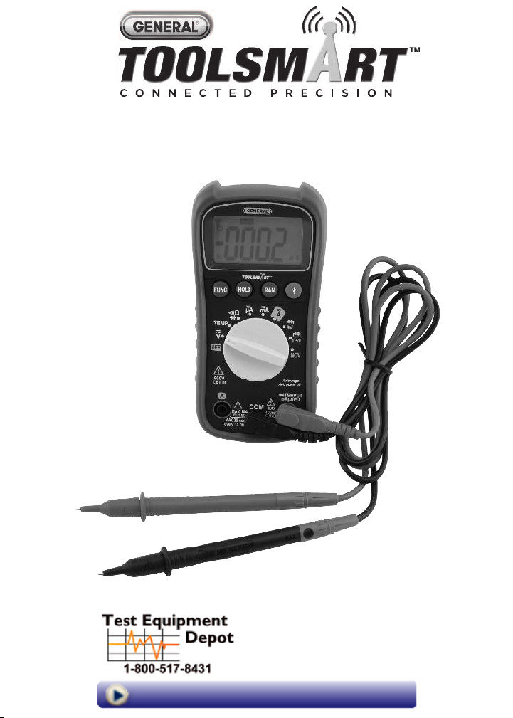
DIGITAL MULTIMETER
USER’S MANUAL
TS04
99 Washington Street
Melrose, MA 02176
Phone 781-665-1400
Toll Free 1-800-517-8431
Visit us at www.TestEquipmentDepot.com
Page 2

TABLE OF CONTENTS
Introduction . . . . . . . . . . . . . . . . . . . . . . . . . . . . . . . . . . . . . . 3
Key Features . . . . . . . . . . . . . . . . . . . . . . . . . . . . . . . . . . . . . . 3
What’s in the Package . . . . . . . . . . . . . . . . . . . . . . . . . . . . . . 3
Product Overview . . . . . . . . . . . . . . . . . . . . . . . . . . . . . . . 4 –6
Safety Instructions . . . . . . . . . . . . . . . . . . . . . . . . . . . . . . 5 –7
Setup Instructions . . . . . . . . . . . . . . . . . . . . . . . . . . . . . . . . . 7
Install Battery . . . . . . . . . . . . . . . . . . . . . . . . . . . . . . . . 7
Operating Instructions . . . . . . . . . . . . . . . . . . . . . . . . . . 8 – 13
General Instructions . . . . . . . . . . . . . . . . . . . . . . . . . . . 8
Holding Readings . . . . . . . . . . . . . . . . . . . . . . . . . . . . . 8
Choosing a Measurement Range . . . . . . . . . . . . . . . . . . 9
Disabling Auto Power Off . . . . . . . . . . . . . . . . . . . . . . . . 9
Measuring AC or DC Voltage . . . . . . . . . . . . . . . . . . . . . 9
Measuring AC or DC Current . . . . . . . . . . . . . . . . . 9 – 10
Measuring Resistance . . . . . . . . . . . . . . . . . . . . . . . . . 11
Measuring Temperature . . . . . . . . . . . . . . . . . . . . . . . 11
Checking for Continuity . . . . . . . . . . . . . . . . . . . . . . . . 12
Checking the Integrity of a Diode . . . . . . . . . . . . . . . . 12
Checking Battery Voltage . . . . . . . . . . . . . . . . . . . . . . 13
Using the NCV Detector . . . . . . . . . . . . . . . . . . . . . . . . 13
Using the Digital Multimeter with the ToolSmart
and an Apple iOS or Android Smartphone . . . . . . . . . . 13
Specifications . . . . . . . . . . . . . . . . . . . . . . . . . . . . . . . . 14 – 15
Operating & Maintenance Tips . . . . . . . . . . . . . . . . . . . . . . . 16
Warranty Information . . . . . . . . . . . . . . . . . . . . . . . . . . . . . . 17
Return for Repair Policy . . . . . . . . . . . . . . . . . . . . . . . . . . . . 17
FCC Statement . . . . . . . . . . . . . . . . . . . . . . . . . . . . . . . . . . . 18
™
App
2
Page 3

INTRODUCTION
Thank you for purchasing General Tools & Instruments’ (General’s) TS04
ToolSmart
and thoroughly before using the instrument.
The DMM can be used as a standalone multimeter, or with General’s free
ToolSmart
iPhone
the phone all measurements it makes. The phone initiates the data transfer
using the ToolSmart
Store or Google Play Store. The measurements can then be used to tag photos
taken by the phone’s camera. For example, the app can apply current readings
to icons of different AC outlets in a rendering of a room as a way to compare
their efficiency.
iPhone®and iTunes®are trademarks of Apple Inc., registered in the U.S. and other countries.
Android™is a trademark of Google Inc.
The Bluetooth®word mark and logos are registered trademarks owned by Bluetooth SIG, Inc. and
any use of such marks by General Tools & Instruments is under license.
™
Digital Multimeter (DMM). Please read this user’s manual carefully
™
app running on your mobile phone. When used in concert with an
®
or Android™smartphone, the DMM can stream—via Bluetooth®— to
™
app, which can be downloaded from the iTunes®App
KEY FEATURES
• 10 functions, 26 ranges
• Measures AC/DC voltage, AC/DC current, resistance and surface
temperature
• Also checks continuity, diode integrity and battery voltage
• Non-contact voltage (NCV) detector
• ETL certified safe for CAT III 600V use
• True RMS measurements
• 2 in. (51mm) diagonal, 3-3/4 digit (4000 count) LCD with 3/4 in. (19mm)
high digits
• Powered by “9V” battery (included)
• Low battery indication
WHAT’S IN THE PACKAGE
The meter is supplied in a display box along with a pair of double-insulated test
lleads, a bead thermocouple probe and plug adapter, and a “9V” battery.
3
Page 4

PRODUCT OVERVIEW
TEMP
mAµAVΩ
µA
A
mA
Ω
Fig. 1 shows the labels and positions of the controls, LCD and physical
structures of the meter. Fig. 2 shows all possible indications on the LCD.
Familiarize yourself with the functions and meanings of all controls, indications
and connectors before moving on to the safety, setup and operating instructions.
1. LCD
2. Activates Bluetooth transmission
3. Range selector. Selects Autoranging or
Manual Ranging mode and specific
manual range, if manual ranging is
selected (see page 8)
4. Four-function FUNC button. 1) Toggles
between AC and DC measurement with
the rotary dial in the ,
, or
position. 2) Selects resistance
measurement, continuity checking or
diode checking with the rotary dial in
the position. 3) Toggles between ºC
and ºF units with the rotary switch in the
TEMP position. 4) Disables the meter’s
Auto Power Off function when pressed
and held while moving the rotary
function switch out of the OFF position.
5. Data hold button. “Freezes” the display when pressed. Cancels the hold
function when pressed again.
6. Rotary switch. Selects the meter’s primary function.
7. A input jack
8. COM input jack
9. main input jack (for all functions except measuring current >400mA)
10. NCV sensor and visual indicator (red LED)
11. Battery compartment cover/flip-up stand (on back)
햲
햵
햶
햷
햸
햹
Fig. 1. The DMM's controls,
indicators and
physical features
햻
햽
햳
햴
햺
4
Page 5
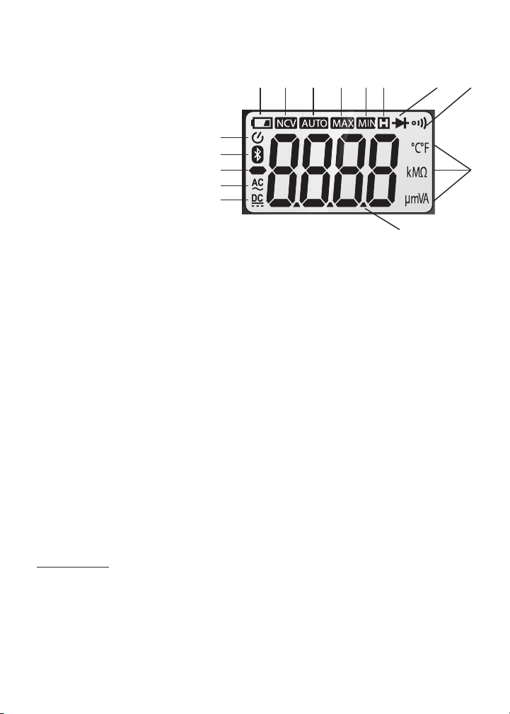
1. Indicates DC voltage or current measurement
2. Indicates AC voltage or current measurement
3. Negative polarity indicator
햺
햻
햹햸햷
햽
햾
4. Bluetooth enabled indicator
5. Indicates Auto power off
function is enabled
6. Low battery indicator
7. Indicates detection of noncontact voltage
8. Autoranging mode indicator
9. Indicates LCD is showing maximum session value
10. Indicates LCD is showing minimum session value
햶
햵
햴
햳
햲
헁
Fig. 2. All possible
display indications
11. Indicates data is being held
12. Diode check mode indicator
13. Continuity check mode indicator
14. Measurement units
15. Measured value
SAFETY INSTRUCTIONS
To avoid possible electric shock or personal injury, and to avoid damaging the
meter or the equipment under test:
• Before using the meter, inspect the case. Do not use the meter if it is
damaged. Look for cracks or missing plastic. Pay particular attention to the
insulation around the connectors.
•
WARNING
Check the test leads for continuity. Replace damaged test leads before using
the meter.
• Verify the meter’s operation by measuring a known voltage. Do not use the
meter if it operates abnormally. Protection may be impaired. When in doubt,
have the meter serviced.
Inspect the test leads for damaged insulation or exposed metal.
Warning
햿
헀
5
Page 6

•
TEMP
mAµAVΩ
µA
mA
A
WARNING
meter, between the and
Do not apply more than the rated voltage, as marked on the
COM
jacks or between any jack and ground.
Also do not input more than the rated current, as marked on the meter,
A
through the
•
WARNING
jack.
Do not measure voltages above 600V in Category III
installations.
•
WARNING
Do not attempt to measure voltage with the rotary function
switch in any position other than . Never attempt to measure current with
the rotary function switch in any position other than , or .
• Use caution when working with voltages above 42VAC
, or 60VDC. These
RMS
voltages pose a shock hazard.
•
•
WARNING
WARNING
Do not operate the meter around explosive gas, vapor, or dust.
When using the probes, keep your fingers behind the finger
guards. Do not touch the metal probes of the test leads when making a
measurement.
• When making connections, connect the black (–) test lead before connecting
the red (+) test lead; when disconnecting, disconnect the red (+) test lead
before disconnecting the black (–) test lead.
• Disconnect circuit power and discharge all high-voltage capacitors before
measuring/testing resistance, continuity or diodes.
• For all DC functions in both auto and manual ranging mode, to avoid the risk
of shock due to possible improper reading verify the presence of any AC
voltages by first using the AC function. Then select a DC voltage range as
wide or wider than the AC range.
• Before measuring current, turn off power to the circuit before connecting the
meter.
• Do not operate the meter with the case (or part of the case) removed.
• Replace the battery as soon as the low battery indicator appears.
Operated with a weak battery, the meter might produce false readings that
could lead to electric shock and personal injury.
• Remove the test leads from the meter before opening the meter case or
battery compartment.
6
Page 7
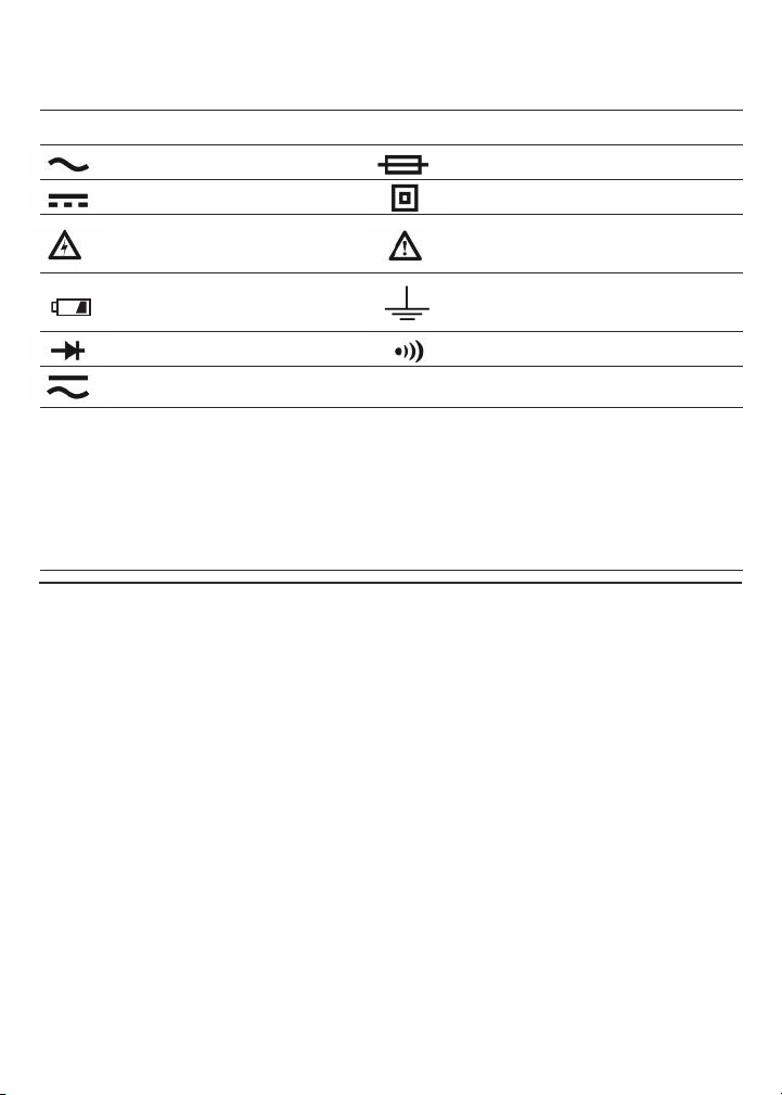
Electrical Symbols Used On the Meter and
In This Manual
Symbol Description Symbol Description
AC (Alternating Current) Fuse
DC (Direct Current) Double-insulated
Caution, risk of electric Risk of danger. Important
shock. Hazardous voltage. information. Refer to the manual.
Low battery indication Earth ground
Diode Continuity beeper
AC or DC Ω Resistance
CAT III For measurements
made on building
equipment such as
distribution panels, feeders
and short branch circuits,
and on lighting systems
in large buildings.
SETUP INSTRUCTIONS
INSTALL BATTERY
Turn the meter over to gain access to the battery compartment.
To open the compartment:
1)
Use a small Phillips-head screwdriver to remove the single screw in the middle
of the one-piece battery compartment cover/flip-up stand.
2) Remove the cover/stand and set it aside.
3) Plug the "9V" battery included in the package into the wired socket inside
the compartment. The terminals of the battery and the socket mate in only
one way, with the smaller male terminal plugging into the larger female
terminal.
4) Secure the battery compartment by replacing the cover/stand and
reinstalling and tightening the Phillips-head screw.
7
Page 8

OPERATING INSTRUCTIONS
TEMP
mAµAVΩ
GENERAL INSTRUCTIONS
All parameters are measured through the included test leads. Unless you are
measuring currents larger than 400 mA, plug the red test lead into the
OM
jack and the black test lead into the C
400 mA, plug the red lead into the A jack (Fig. 1, Callout 7) and the black lead
into the COM jack.
HOLDING READINGS
Pressing the HOLD button “freezes” any measurement on the LCD and causes
the symbol to appear on the top line. Pressing the button again releases the
hold, removes the symbol and resumes real-time measurements.
CHOOSING A MEASUREMENT RANGE
By default, the DMM automatically enters Auto Ranging mode when powered
on. In this mode, it chooses the measurement range that maximizes the
resolution of its current, voltage and resistance measurements. The term AUTO
on the top line of the LCD indicates operation in Auto Ranging mode.
To switch to Manual Ranging mode for any parameter, briefly press the
button. This will make the AUTO term disappear and cause the meter to enter
the widest full-scale range available for that parameter (see the Specifications
section beginning on p. 14 for a list of the measurement ranges available for
voltage, current and resistance).
Once the meter is in manual ranging mode, each subsequent brief press of the
RAN button typically narrows the full-scale range by an order of magnitude (a
factor of 10). For example, briefly pressing the RAN button with the meter
operating in the 0 to 40V full-scale manual range reduces the full-scale range
to 0 to 4V (and improves measurement resolution). The next press of the button
reduces the range to 0 to 400mV. When the narrowest full-scale range has
been reached, the next press of the RAN button switches the meter back to the
largest full-scale manual range for the selected parameter.
To exit Manual Ranging mode and return to Auto Ranging mode, press and
hold the RAN button.
8
jack. To measure currents larger than
RAN
Page 9

DISABLING AUTO POWER OFF
DC
A
C
DC
TEMP
mAµAVΩ
TEMP
mAµAVΩ
By default, the DMM will automatically power itself off following any period of
15 minutes of front-panel inactivity. The icon at the upper left of the LCD
indicates that the Auto Power Off function is enabled. To disable the APO
function, press and hold the FUNC button while powering on the meter by
moving the rotary function switch to any position other than OFF. This will
cause the icon to disappear.
MEASURING AC OR DC VOLTAGE
Warning
Do not measure any AC or DC voltage higher than 600V. Doing so may damage
the meter’s internal circuitry.
(1) Turn the rotary switch to the position. By default, doing so will prepare the
DMM to measure DC rather than AC voltage, indicated by the presence of
the icon at the lower left of the LCD. If you are certain that the voltage
you want to measure is DC voltage, proceed to Step (2).
If you know that the voltage you want to measure is AC voltage, press the
FUNC button once; this will cause the icon to replace the icon on the
left side of the LCD. If you are unsure whether the voltage to be tested is AC
or DC, configure the DMM to measure AC voltage for safety reasons.
(2) Plug the black test lead into the front-panel COM jack and the red test lead
into the jack.
(3) Touch the black test lead to the lower-potential point of the circuit under
test, and the red test lead to the higher-potential point.
(4) Read the measured voltage on the display. If you are working in Manual
Ranging mode and the readout is .OL, the voltage level is beyond the
currently selected range. If that is the case, use the FUNC button to select
the next-widest position. When measuring DC voltage, if the test leads are
reversed a minus sign will appear at the left of the readout.
MEASURING AC or DC CURRENT
Do not attempt to measure: 1) currents larger than 400mA through the
Warning
jack; 2) currents larger than 10A through the A jack; or 3) currents larger than
2A through the A jack for more than 2 minutes continuously; pause 10 minutes
after each measurement of such a large current.
9
Page 10

(1) Remove power from the circuit to be tested and discharge all high-voltage
A
mA
µA
mA
µA
A
C
DC
DC
TEMP
mAµAVΩ
TEMP
mAµAVΩ
mA
µA
A
capacitors.
(2) Turn the rotary switch to the , or position,, depending on the
amplitude of the current you expect to encounter. If you are unsure of the
amplitude, select the 10A position first and then switch to the or
position if all of your measurements are less than 400mA.
(3) By default, the DMM is initially configured to measure DC rather than AC
current, indicated by the presence of the icon at the lower left of the
LCD. If you are certain that the current you want to measure is DC current,
proceed to Step (4).
If you know that the current you want to measure is AC current, press the
FUNC button once; this will cause the icon to replace the icon on the
left side of the LCD. If you are unsure whether the voltage to be tested is AC
or DC, configure the DMM to measure AC voltage for safety reasons.
(4) Plug the black test lead into the black COM jack at the bottom left of the
front panel.
(5) Plug the red test lead into the A or jack. Choose the A jack if you
have set the rotary switch to the position, and the jack if you have
set it to the or position.
(6) Break the circuit and touch the red lead to the higher-voltage side of the
break and the black lead to the lower-voltage side.
(7) Re-apply power to the circuit and observe the display. If you are working in
Manual Ranging mode and the display shows O.L, the current amplitude is
beyond the selected current range. If that is the case, use the FUNC button
to select the next-widest position. If the readout is a negative value, the
leads are reversed but the absolute value represents a valid measurement
of current amplitude.
(8) Remove power from the circuit and discharge all high-voltage capacitors.
(9) Remove the test leads and restore the circuit to its original condition by
eliminating the break you made in Step 6.
10
Page 11
MEASURING RESISTANCE
Ω
TEMP
mAµAVΩ
TEMP
mAµAVΩ
Warning
To avoid electrical shock or damage to the meter when measuring resistance,
turn off all power to the circuit and discharge all high-voltage capacitors.
(1) Turn the rotary switch to the position and press the FUNC button until
Ω
, kΩor MΩappears on the right side of the LCD.
(2) Plug the black test lead into the front-panel COM jack and the red test lead
into the jack.
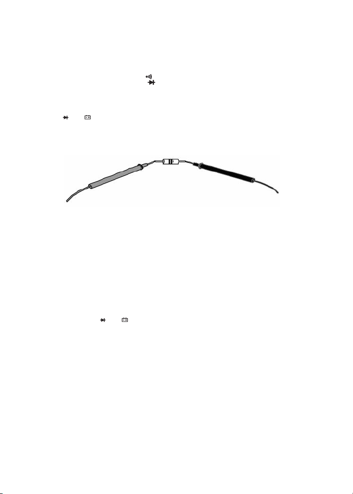
(3) Measure the resistance by touching the test leads to the desired test points
of the circuit or to the terminals of a component, as shown below.
RED TEST LEAD
BLACK TEST LEAD
(4) Read the measured resistance on the display. If you are working in Manual
Ranging mode and the readout is .OL, the resistance value is beyond the
currently selected range. If that is the case, use the FUNC button to select
the next-widest position.
MEASURING TEMPERATURE
The DMM includes a “K” type bead thermocouple probe for measuring surface
temperatures. To use it,
(1) Insert the +V plug of the plug adapter to which the thermocouple is
attached into the jack.
(2) Insert the COM plug of the plug adapter into the COM jack of the DMM.
(3) Turn the rotary switch to the TEMP position.
(4) Press the FUNC button until your preferred temperature measurement
unit—ºF or ºC—appears on the right side of the LCD.
(5) Attach the bead probe to the surface whose temperature you wish to
measure. The reading will be shown on the LCD.
11
Page 12

CHECKING FOR CONTINUITY
TEMP
mAµAVΩ
Ω
TEMP
mAµAVΩ
Ω
Warning
To avoid possible damage to the meter or other equipment, turn off the power
source and discharge all high-voltage capacitors.
(1) Turn the rotary switch to the position and press the FUNC button until
the icon appears in the upper right corner of the LCD.
(2) Plug the black test lead into the COM jack and the red test lead into the
jack.
(3) Touch the test leads to any two points of the circuit. The resistance between
those two points will be displayed. If the resistance is <50Ω, the beeper will
sound continuously. If there is no continuity (an open circuit or a resistance
>50Ω) between the two points, OL. will appear on the readout.
CHECKING THE INTEGRITY OF A DIODE
Warning
To avoid possible damage to the meter or other equipment, turn off the power
source and discharge all high-voltage capacitors.
(1) Turn the function switch to the position and press the FUNC button until
the icon appears in the upper right corner of the LCD.
(2) Plug the black test lead into the front-panel COM jack and the red test lead
into the jack.
(3) Touch the red test lead to the anode (positive terminal) of the diode to be
tested and the black test lead to its cathode (negative terminal), as shown
below.
RED TEST LEAD BLACK TEST LEAD
(4) Read the diode’s forward bias voltage drop on the display. A silicon diode
typically has a forward voltage drop of 0.7V. A germanium diode typically
has a forward voltage drop of 0.3V. A 0V reading in both directions indicates
a shorted diode. A readout of .OL means either of two things: the leads are
reversed, or the diode is defective. Reverse the leads. If this still produces a
readout of .OL, the diode is defective and should be replaced.
12
Page 13

CHECKING BATTERY VOLTAGE
TEMP
mAµAVΩ
TEMP
mAµAVΩ
Warning
To avoid possible electrical shock or damage to the meter, do not apply a
voltage greater than 600V between the meter’s and
COM jacks.
(1) Turn the rotary switch to the 9V or 1.5V position, corresponding to the
nominal voltage of the battery to be tested.
(2) Plug the black test lead into the COM jack and the red test lead into the
jack.
(3) Touch the red test lead to the battery’s anode (+ terminal) and the black test
lead to its cathode (– terminal). The battery’s voltage will appear on the
display.
USING THE NCV DETECTOR
To check whether a line, cable or AC outlet is “hot”
(energized), touch it with
the top of the meter or bring the top within 1/4 inch of it after moving the rotary
function switch to the NCV position. If the beeper sounds repeatedly and the
red LED at the top of the meter (Fig. 1, Callout 10) flashes rapidly, the line or
outlet is carrying at least 110VAC
USING THE DMM WTH THE ToolSmart
RMS
.
™
APP AND
AN APPLE iOS OR ANDROID SMARTPHONE
To stream measurements and calculations made by the DMM to an Apple iOS
or Android smartphone, begin by downloading the ToolSmart
™
app from the
iTunes Store or Google Play Store to your mobile device.
Once you have downloaded the app, install it. Then, pair the DMM and your
phone by activating Bluetooth on your phone and pressing the button on the
DMM.
A tutorial on the app explains how to save DMM measurements to your phone
and overlay them on photos of your project taken by the phone’s camera.
13
Page 14
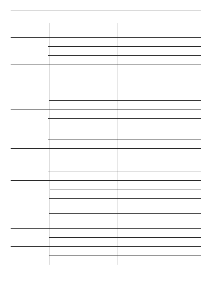
SPECIFICATIONS
Parameter or
Feature/Function
AC voltage Measurement ranges 0 to 4V/40V/400V/600V
DC voltage Measurement ranges 0 to 400mV/4V/40V/400V/600V
AC or DC Measurement ranges 0 to 400uA/4mA/40mA/400mA/10A
current
Resistance Measurement ranges 0 to 400Ω/4kΩ/40kΩ/
Temperature DMM measurement range -4º to 1832ºF (-20º to 1000ºC)
DMM measurement accuracy ±(2.0% of reading + 2 digits)
Measurement accuracy of ±(2% + 2 digits)
Continuity Open circuit voltage 1V
Diode integrity Range 0 to 2.7V
Attribute Specification
Measurement accuracy ±(1% of reading + 10 digits)
Maximum resolution 1mV
Measurement accuracy ±(0.8% of reading + 5 digits)
in 600V range;
±(0.5% of reading + 2 digits)
in other ranges
Maximum resolution 0.1mV
Measurement accuracy ±(2% of reading + 3 digits) in
10A range; ±(1.2% of reading
+ 6 digits) or better in other ranges
Maximum resolution 0.1A
400Ω/4MΩ/40MΩ
Measurement accuracy ±(0.8% of reading + 3 digits), typical)
Maximum resolution 0.1Ω
Measurement range of -4° to 500°F (-20° to 260°C)
included thermocouple
Included thermocouple
Threshold <50Ω
Resolution 1mV
14
Page 15
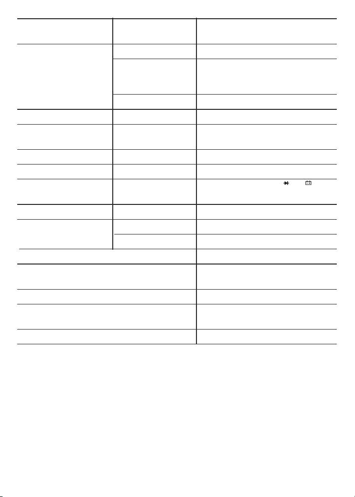
Parameter
TEMP
mAµAVΩ
Feature/Function
or
Attribute Specification
Battery voltage Measurement ranges 0 to 9V, 0 to 1.5V
Measurement ±(0.8% of reading + 7 digits)
9V
accuracy in
reading + 5 digits) in
position; ±(3% of
1.5V
position
Max resolution 1mV
Safety rating CAT III 600V
NCV detection >110VAC
RMS
voltage & distance @ <1/4 in. (6mm)
Bluetooth range 33 ft. (10m)
Maximum input voltage 600VDC/AC
RMS
Fuse protection 400mV/600V fuse for jack;
10A/600V fuse for Ajack
Sampling time 3X/sec
Display No. of digits 3-3/4
Maximum count 4000
Low battery indication threshold <6.7VDC
Operating temperature 32° to 104°F (0° to 40°C)
@<80%RH
Power source (1) “9V” battery (included)
Dimensions 5.8 x 2.9 x 2.0 in.
(148 x 74 x 50mm)
Weight (including battery) 8.2 oz. (232g)
Note: Accuracy values are stated for an operating temperature between
64° and 82°F (18° and 28°C) with RH<80%. Accuracies are lower outside
this range, in proportion to the actual operating temperature's distance
from the “sweet spot.”
15
Page 16
OPERATING & MAINTENANCE TIPS
TEMP
mAµAVΩ
When the icon appears in the upper left corner of the LCD, immediately
replace the meter’s “9V” battery by following the instructions on page 7.
To replace a blown fuse:
1. Power off the meter.
2. Unplug the test leads.
3. Turn the meter over and loosen the small Phillips-head screw in the middle
of the back that secures the meter’s battery compartment cover. Remove the
cover, taking care not to lose the screw.
4. Remove the meter’s gray rubber holster by carefully pulling its front lip over
the housing, starting at the top and working your way around the perimeter
to the bottom.
5. Remove the four larger Phillips-head screws that secure the two halves of
the housing and pull the two halves apart.
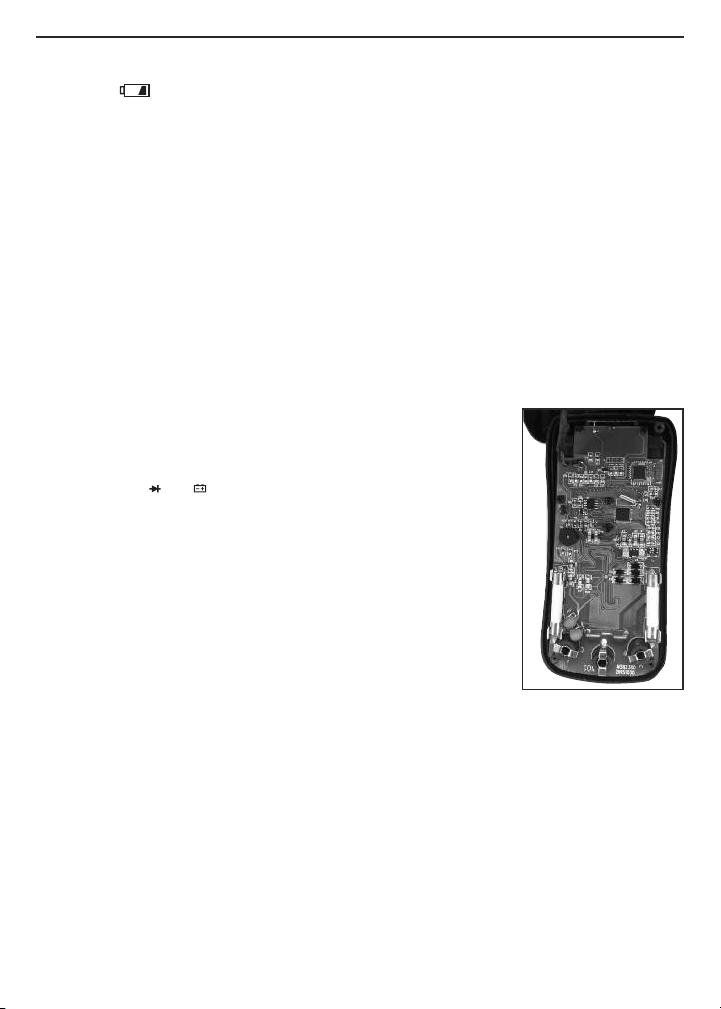
6. Locate the blown fuse on the circuit board (see photo at
right). The DMM uses two different white cylindrical
fuses. The jack is protected by an F400mA/600V
fuse. The A jack is protected by an F10A/600V fuse.
Each fuse is located directly behind the jack it protects.
7. Using another multimeter or a continuity checker, verify
that the suspected blown fuse produces a resistance
reading consistent with an open circuit.
8. Replace the blown fuse by a fuse with the same current
and voltage ratings.
9. Rejoin both halves of the housing by replacing and
tightening its four screws.
10. Replace the battery compartment cover and tighten its screw.
11. Replace the gray rubber holster.
After subjecting the meter to a large change in ambient temperature, wait at
least 30 minutes before making measurements to guarantee the accuracy of
readings.
Remove the battery when storing the meter or when you do not expect to use it
for an extended period of time (months rather than weeks).
Do not disassemble the meter or immerse it in water.
16
Where to find the DMM’s
cylindrical white ceramic
fuses
Page 17

WARRANTY INFORMATION
General warrants its instruments and accessories, and digital tools products against
defects in material or workmanship for one year from the date of purchase unless
otherwise stated on the packaging, manual, and/or marketing materials. General
also warrants its non-digital tools products against defects in material or
workmanship on a limited lifetime term.
General will replace or repair the defective unit, at its option, subject to verification
of the defect.
This warranty does not apply to defects resulting from abuse, neglect, accident,
unauthorized repair, alteration, or unreasonable use of the product. It also does not
cover products purchased from unauthorized distributors. A proof of purchase must
accompany each warranty claim.
Any implied warranties arising from the sale of a General product, including but not
limited to implied warranties of merchantability and fitness for a particular purpose,
are limited to the above. General shall not be liable for loss of use of the product or
other incidental or consequential damages, expenses, or economic loss, or for any
claim of such damage, expenses, or economic loss.
State laws vary. The above limitations or exclusions may not apply to you.
For more details or to file a warranty claim, contact General Tools & Instruments
Technical Support at [email protected].
RETURN FOR REPAIR POLICY
Every effort has been made to provide you with a reliable product of superior
quality. However, in the event your instrument requires repair, please contact
our Customer Service to obtain an RGA (Return Goods Authorization) number
before forwarding the unit via prepaid freight to the attention of our Service
Center at this address:
General Tools & Instruments
75 Seaview Drive
Secaucus, NJ 07094
212-431-6100
Remember to include a copy of your proof of purchase, your return address,
and your phone number and/or e-mail address.
17
Page 18

FCC STATEMENT
This device complies with part 15 of the FCC Rules. Operation is subject to the
following two conditions: (1) This device may not cause harmful interference,
and (2) This device must accept any interference received, including
interference that may cause undesired operation.
This equipment has been tested and found to comply with the limits for a Class
B digital device, pursuant to part 15 of the FCC Rules. These limits are designed
to provide reasonable protection against harmful interference in a residential
installation. This equipment generates, uses and can radiate radio frequency
energy and, if not installed and used in accordance with the instructions, may
cause harmful interference to radio communications.
However, there is no guarantee that interference will not occur in a particular
installation. If this equipment does cause harmful interference to radio or
television reception, which can be determined by turning the equipment off and
on, the user is encouraged to try to correct the interference by one or more of
the following measures:
• Reorient or relocate the receiving antenna.
• Increase the separation between the equipment and receiver.
• Connect the equipment to a different circuit than the one the receiver is
connected to.
• Consult your supplier or an experienced radio/TV technician for help.
Caution: Any changes or modifications not expressly approved by the party
responsible for compliance could void the user's authority to operate the
equipment.
18
Page 19

NOTES
__________________________________________________________
__________________________________________________________
__________________________________________________________
__________________________________________________________
__________________________________________________________
__________________________________________________________
__________________________________________________________
__________________________________________________________
__________________________________________________________
__________________________________________________________
__________________________________________________________
__________________________________________________________
__________________________________________________________
__________________________________________________________
__________________________________________________________
__________________________________________________________
__________________________________________________________
19
Page 20
NOTICE - WE ARE NOT RESPONSIBLE FOR TYPOGRAPHICAL ERRORS.
General Tools & Instruments
GeneralToolsNYC
99 Washington Street
Melrose, MA 02176
Phone 781-665-1400
Toll Free 1-800-517-8431
Visit us at www.TestEquipmentDepot.com
Specifications subject to change without notice
©2016 GENERAL TOOLS & INSTRUMENTS
MAN# TS04
01/14/16
 Loading...