

Page 1
Page 2

CONTENTS
SUMMARY
SPECIFICATIONS
SAFETY WARNINGS & CAUTIONS
UNPACKING
SETTING
CONNECTING THE TOOL TO AN AIR SUPPLY
LOADING THE FASTENERS
OPERATING THE TOOL
REGULAR MAINTENANCE
1
1
1
2
2
3
3
3
3
TROUBLE SHOOTING
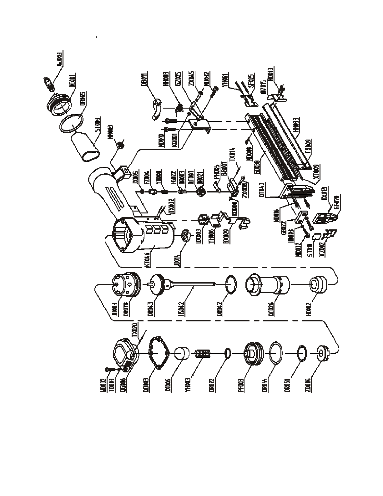
EXPLODED VIEW DRAWING
PARTS LIST
4
5
6
Page 3

READ ALL INSTRUCTIONS BEFORE OPERATING THE TOOL
SUMMARY
You will need the instruction for the safety warning and precautions, assembly instruction, operating and main-
tains procedures, parts list and diagram. Keep your invoice with this instruction. Write the invoice number on
the inside of the front cover. Keep the instruction and invoice in a safe and dry place for future reference.
SPECIFICATIONS
Characteristic
Minimum Operating Air Pressure
Maximum Operating Air Pressure
Nail Length Range
Nail Size
Nail Capactity
Air Inlet
Air Consumption
Tool Weight
Value
60 PSI
95 PSI
5/8" -- 1-1/4"
18 & 19 Gauge
100
1/4" NPT
0.38L at 80PSI
2.7 lbs
SAFETY WARNINGS& CAUTIONS
1.KEEP WORKING AREA CLEAN. Cluttered areas invite injuries.
2.DON’T ALLOW CHILDREN KEEP AT THE WORKING AREA. Don’t let them handle the tool.
3.DO NOT OPERATE THIS TOOL IF UNDER THE INFLUENCE OF ALCOHOL OR DRUGS.
Read warning label on prescriptions to determine if your judgment or reflexes are impaired while taking
drugs. If there is any doubt, do not attempt to operate.
4.USE SAFETY GLASSES. Safety glasses should conform to ANSI Z87.1 specifications. Before operating,
wear safety glasses against flying debris from the front and side. Safety glasses should be worn when
loading, operating, unloading or servicing this tool.
5.USE EAR PROTECTION. The working area may be exposed to high noise levels that can lead to
hearing damaged.
6.NEVER USE OXYGEN COMBUSTIBLE GASES, BOTTLED GASES OR HIGH PRESSURE
COMPRESSED GAS AS A POWER SOURCE FOR THIS TOOL. The tool may explode and
cause serious injury.
7.DRESS SAFELY. Protective gloves and nonskid footwear or safety shoes are recommended when
working with and operating this tool. Don’t wear loose clothing or jewelry. They can get caught in moving
parts. Also, wear a protective hair covering to prevent long hair from getting caught in the tool.
8.DO NOT FIRE TO HARD MATERIALS. Do not attempt to shoot toward hard or brittle material
such as concrete, steel or tile.
9.WHEN OPERATING TOOL. keep the proper footing and balance to avoid damaged resulting from
losing balance.
10.CHECK DAMAGED PARTS. Before using tool, carefully check if there is any part damaged.
11.REPLACE PARTS AND ACCESSORIES. Only allow use same replacement parts while servicing.
Approved accessories and replacement parts are available.
12.KEEP ALERT. Watch what you are doing. Use common sense. Do not operate any tool when you are
tired.
1
Page 4
13.STORE THE TOOL. When not in use, tool should be cleaned, fully assembled and then, stored in a dry
QUICK
CONNECTOR
AIR SUPPLY
REGULATOR
location to reduce rust. For safety, keep out of reach of children.
14.OUTDOORS EXTENSION CORDS. When air compressor is used outdoors, use only rounded
jackets extensions cords intended for outside use. See manufacturer’s manual for the AWG required for
the compressor’s amperage draw.
15.PAY ATTENTION TO AIR HOSE AND THEIR CONNEATIONS. Don’t trip over hoses. Make
sure all connections are tight.
16.AFTER LOADING THE FASTENERS. never point the tool at yourself or bystanders.
17.USE THE CORRECT AIR CONNECTOR. The connector on the tool must not hold pressure when
the air supply is disconnected. If the wrong fitting is used, the tool can be charged with air after being
disconnected and still be able to drive a fastener.
18.WHEN CONNECTING THE AIR. The tool may possibly fire the fasteners as soon as you plug it in to
air hose. Therefore, remove all the fasteners before connecting to the air.
19.DO NOT DEPRESS THE SAFE BRACKET AND THE TRIGGER WHEN LOADING.
20.IF THE FASTENERS ARE JAMMED. Disconnect the tool from the air and remove the jammed
fasteners out.
WARNING: The warning, caution, and instructions explained in this instruction manual cannot
cover all possible conditions and situations that may occur. It must be understood by the operator that COMMON SENSE AND CAUTION ARE FACTORS WHICH CANNOT BE BUILT
INTO THIS PRODUCT, BUT MUST BE SUPPLIED BY THE OPERATOR.
UNPACKING
When unpacking, check and make sure that all the accessories are included. If anyone is missed or
broken, please call seller for help. Refer to the follow lists.
Description
Nailer
S3 Hex Key
S4 Hex Key
Air Tool Oil
Operating instruction
Qty
1
1
1
1
1
SETTING
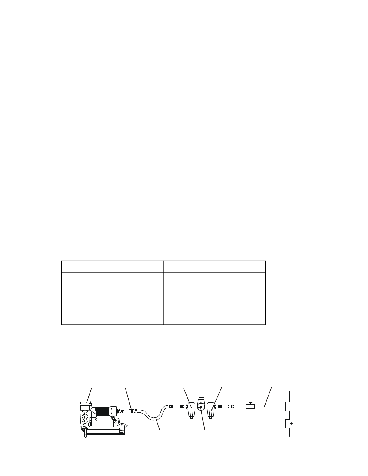
Your air tool is fully assembly when you receive it. Before using it, attach the air line and desired air system
accessories. See Figure 1 for the recommended accessories and connection order. Be sure the air hose is
depressurized when installing or removing adapters to the air line.
NAILER
OILER FILTER
AIR HOSE
Figure 1
2
Page 5
CONNECTING THE TOOL TO AN AIR SUPPLY
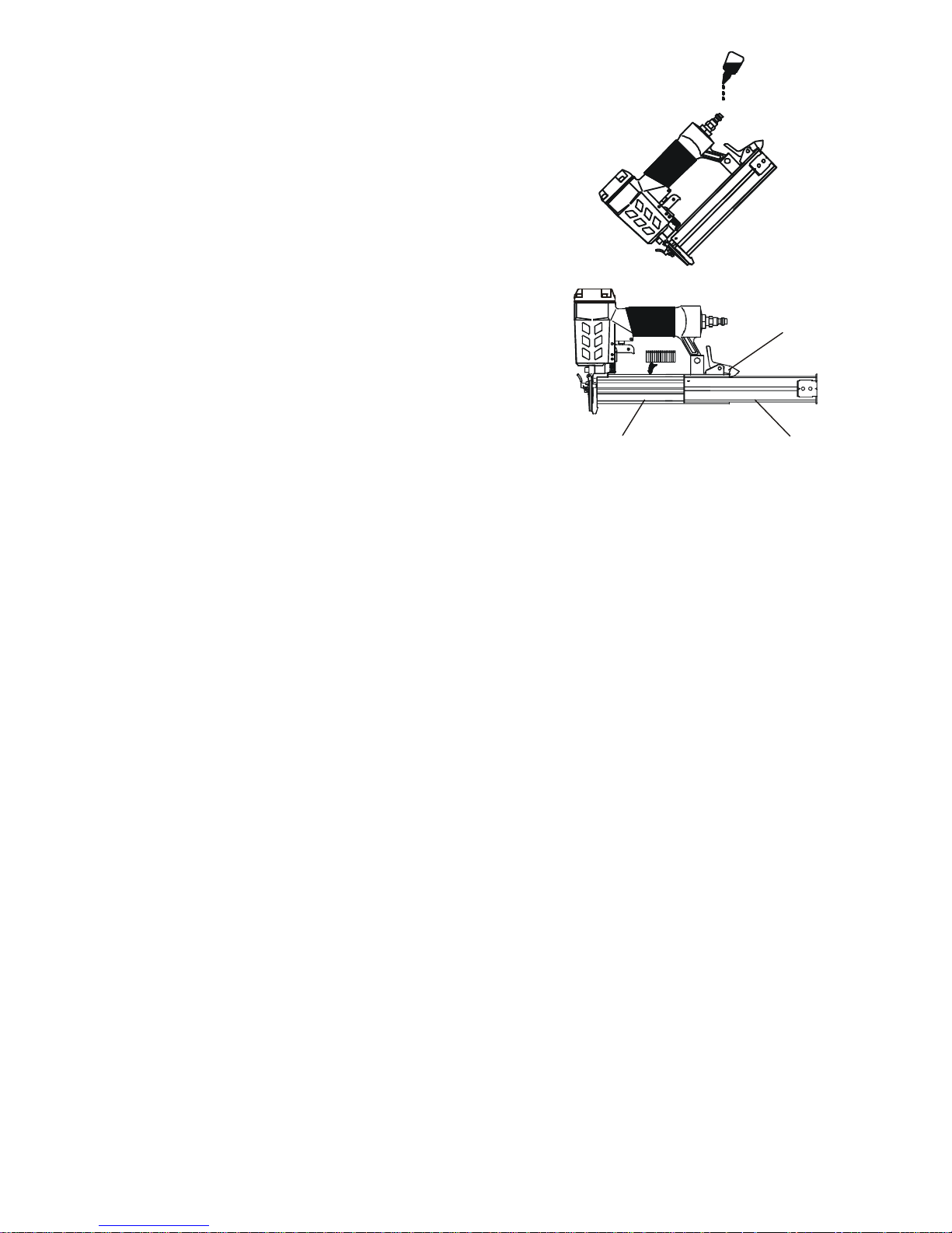
MOVABLE MAGAZINE
1. Determine if the tool needs oil and, if necessary, place two drops of
oil in the AIR PLUG(GJ003) as shown in Figure 2. If you are using an
automatic in-line oiler, check and add oil if necessary.
2. Turn the compressor on and set the regulator to the proper pressure
for the size and type of fastener being used.
3. Connect the tool to the air supply (see Setup for air supply connec-
tion recommendations).
Figure 2
LOADING THE FASTENERS
1. Depress the LOCK(DB011) to release the MOVABLE MAGA-
ZINE (HM033) and pull the magazine out fully as shown in Figure
3.
2. Place a full clip of the specified type and size fasteners on the
FIXED MAGAZINE (GD038), up to 100 fasteners may be loaded
in the magazine.
3. Push the MOVABLE MAGAZINE ASSEMBLY forward until
it was locked.
FIXED MAGAZINE
Figure 3
LOCK
OPERATING THE TOOL
Test the driving depth in a sample piece of wood before using. If the fasteners are being driven too far or not
far enough, adjust the regulator to provide less air pressure or more air pressure.
1. Connect the tool to the air supply. Make sure the air pressure is in correct range denoted in section of
SPECIFICATIONS.
2. Load fastener as above the direction given in the section called LOAD THE FASTENER.
3. Hold the Body (KT046) and press the Drive guide (DT047) and safe bracket to work surface , being sure the
tool is straight and then gently depress the Trigger (BB007) to drive the fastener.
4. Lift the tool off the work surface.
5. The tool has two driving modes:
1). Put the drive guide on the working surface, lightly push the tool toward the working surface until the
safe bracket is depressed, then, depress the trigger to drive the fastener.
2). First, depress the Trigger, then, repeatedly impact the Safe bracket, the tool can repeatedly drive the
fasteners. The tool will drive one fastener when the Safe bracket is impacted one time.
REGULAR MAINTENANCE
1. Frequent, but not excessive, lubrication is required for best performance. Oil added through the airline con-
nection will lubricate internal parts. An automatic airline oilier is recommended but oil may be added manually
before every operation or after about 1 hour of continuous use. Only a few drops of oil at a time are necessary.
Too much oil will collect inside the tool and be blown out during the exhaust cycle. ONLY USE PNEUMATIC
TOOL OIL. Do not use detergent oil or additives, as these lubricants will cause accelerated wear to the seal
in the tool.
2. Use a small amount of oil on all moving surface and pivots.
3. Dirt and water in the air supply are major causes of pneumatic tool wear. Use a filter/oiler for better
performance and longer life. The filter must have adequate flow capacity for the specific application. Consult the manufacturer's instructions for proper maintenance of you filter.
4. Keep tools clean for better and safer performance. Use nonflammable cleaning solutions ( CAUTION: Such
solutions may damaged O-ring and other tool parts) only if necessary- DO NOT SOAK.
3
Page 6
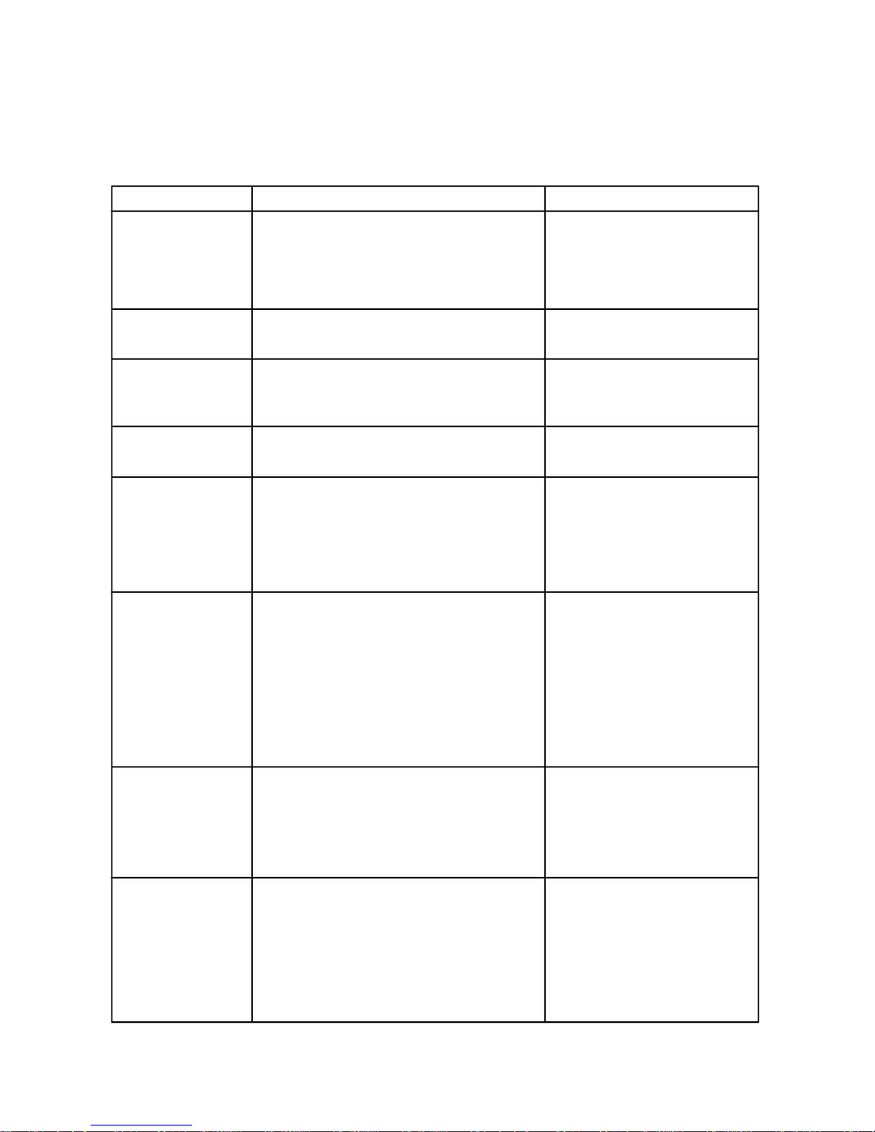
TROUBLE SHOOTING
STOP USING THE TOOL IMMEDIATELY IF ANY OF THE FOLLOWING PROBLEMS
OCCUR. SERIOUS PERSONAL INJURY COULD OCCUR. ANY REPAIRS OR REPLACEMENTS MUST BE DONE BY A QUALIFIED PERSON OR AN AUTHORIZED SERVICE CENTER ONLY.
PROBLEM
Air leaking at
Trigger area
Air leaking between
body and drive guide
Air leaking between
body and cylinder cap
Blade driving fastener
too deeply
Runs slowly or has
power loss
Tool skip a fasteners
PROBLEM CAUSE
1. O-ring in trigger valve are damaged.
2. Trigger valve head are damaged.
3. Trigger valve stem, seal or O-ring are
damaged.
Damaged bumper.
1. Screw loose.
2. Damaged seal.
1. Worn bumper .
2. Air pressure is too higher.
1. Insufficient oil.
2. Insufficient air supply.
3. Broken spring in cylinder cap.
4. Exhaust port in cylinder cap is blocked.
1. Worn bumper or damaged spring .
2. Inadequate airflow to tool.
3. Worn or dry O-ring on piston.
4. Damaged O-ring on trigger valve.
5. Cylinder cap seal leaking.
SOLUTION
1. Check and replace O-ring.
2. Check and replace trigger
valve head.
3. Check and replace trigger
vlave stem, seal or O-ring.
Check and replace bumper.
1. Tighten screws.
2. Check and replace seal.
1. Replace bumper.
2. Adjust the air pressure.
1. Lubricate as instructed.
2. Check air supply.
3. Replace spring.
4. Replace damaged internal
parts.
1. Replace bumper or pusher
spring.
2. Check hose and compressor
fittings.
3. Replace O-ring or lubricate.
4. Replace O-ring.
5. Replace seal.
Fasteners are jammed
Tool will not drive
down tight
1. Fasteners are wrong size or damaged.
2. Magazine or front plate screws are loose.
3. Blade in piston assembly is damaged.
1. Worn blade in piston assembly.
2. Lack of power.
3. Slow cycling and loss of power.
1. Use the recommended and
undamaged fastenerls.
2. Tighten screws.
3. Replace piston assembly.
1. Replace piston assembly.
2. Adjust to adequate air
pressure.
3. Check cylindre cap spring for
broken coils or reduced length.
Check if exhaust port of cylinder cap is restricted.
4
Page 7
EXPLODED VIEW DRAWING
5
Page 8

PARTS LIST
Refer to the Exploded View Drawing for the location of parts listed below.
ITEM
BB007
BX029
DB011
DE001
DT047
DX003
DZ015
FG022
FZ004
GB022
GD038
GF020
GJ003
GZ025
HC002
HM033
HS042
JD014
JQ003
JX005
JX006
KQ001
KT046
ND008
ND010
ND013
ND016
ND032
NH003
NM003
OR003
OR021
DESCRIPTION
TRIGGER
SAFE BRACKET
LOCK
END CAP
DRIVE GUIDE
SAFE GUIDER
STOPPED PLATE
TRIGGER VALVE STEM
TRIGGER VALVE HEAD
PLATE
FIXED MAGAZINE
FRONT PLATE
AIR PLUG
SUPPORT
BUMPER
MOVABLE MAGAZINE
PISTON ASSEMBLY
JOINT GUIDE
COLLAR
SEAL
SEAL
LOCKING WASHER
BODY
SCREW
SCREW
SCREW
SCREW
SCREW
TORSION SPRING
NUT
O-RING 5.5×1.5
O-RING 15×1.9
ITEM
OR022
OR042
OR043
OR051
OR055
OR065
OR078
PF003
PH005
QC026
QD003
QG006
QT007
SF025
ST003
ST010
TD003
TX009
TX013
TX014
TX020
TX032
XT009
YH003
YH006
YH008
YH061
YZ002
ZD004
ZX008
ZX045
DESCRIPTION
O-RING 15.7×2
O-RING 27.3×2
O-RING 27.4×3
O-RING 33.5×3.5
O-RING 36.3×2.5
O-RING 40.2×2.3
O-RING 48.5×2.5
VALVE
TRIGGER SPRING
CYLINDER
GASKET
CYLINDER CAP
TRIGGER VALVE GUIDE
FEEDER SHOE
SOFT GRIP SLEEVE
SLEEVE
SPRING WASHER
SPRING PIN
SPRING PIN
SPRING PIN
SPRING PIN
SPRING PIN
RAIL
SPRING
SPRING
SPRING
SPRING
LATCH
STOPPED PIECE
PIN
PIN
6
 Loading...