

Page 1
243-1145
You will need this manual for safety instructions, operating procedures and warranty.
Put it and the original sales receipt in a safe dry place for future reference.
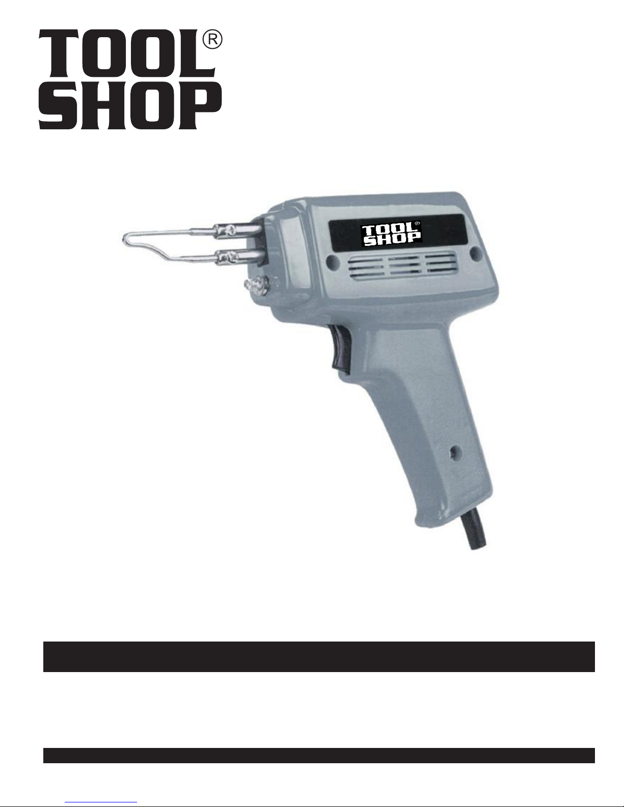
SOLDERING GUN
Operator’s Manual
SAVE THIS MANUAL
Page 2
2
IMPORTANT SAFETY INSTRUCTIONS
!
WARNING
precautions should always be followed to reduce the risk of re, electric
shock, and personal injury.
READ
1. KEEP WORK AREA CLEAN. Cluttered areas can cause injuries.
2. CONSIDER WORK AREA ENVIRONMENT. Don’t use power tools in damp,
3. KEEP CHILDREN AND BYSTANDERS AWAY. All children should be kept
4.
5. OBSERVE PROPER PRECAUTIONS REGARDING DOUBLE INSULA-
6. GUARD AGAINST ELECTRIC SHOCK. Prevent body contact with grounded
7. DO NOT MISUSE THE CORD. Never carry your tools by the cord or pull on
8. WHEN WORKING OUTDOORS, USE AN OUTDOOR-RATED EXTENSION
9. DO NOT EXPOSE ELECTRICAL POWER TOOLS TO MOISTURE. Rain or
10. ENSURE THE EXTENSION CORD YOU USE IS OF SUFFICIENT GAUGE
ALL
wet, or poorly lit locations. Don’t expose tools to the rain. Keep the work area
well lit. Don’t use tools in the presence of ammable gases or liquids.
away from the work area. Don’t let them handle machines, tools or extension
cords.
GROUNDED TOOLS must be plugged into an outlet that is properly
installed and grounded. Grounding provides a low-resistance path to carry
electricity to the ground away from the operator, should the tool malfunction elec-trically. Do not remove the grounding prong from the plug or alter the plug in
any way. If in doubt as to whether the outlet is properly grounded according
to code, check with a qualied electrician.
TION. This tool is double insulated. It is equipped with a polarized plug.
One blade is wider than the other, so it will t into a polarized outlet only one
way. If you have difculty inserting the plug, try reversing it. If it still doesn’t
t , do not alter the plug; have a qualied electrician install a polarized outlet.
surfaces: pipes, radiators, ranges, and refrigerator enclosures. When your
body is grounded the risk of electric shock increases. When working wherever “live” electrical wires may be encountered, try to ascertain whether
there is a danger of shock. DO NOT TOUCH ANY METAL PARTS
OF THE TOOL while using it. Hold the tool only by the plastic grip to prevent
electric shock if you contact a live wire.
the cord to unplug it. Protect the cord from potential sources of damage:
heat, oil & solvents, sharp edges, or moving parts. Replace damaged cords
immediately.
CORD. An extension cord rated for outdoor use must be marked “W-A” or
“W”.
wet conditions can cause water to enter the tool and lead to electric shock.
FOR ITS LENGTH.
: When using electric tools, machines or equipment, basic safety
INSTRUCTIONS BEFORE USING THIS TOOL
Bystanders can be a distraction and can be injured.
Recommended Minimum Wire Gauge for Extension Cords
Amps
from
Tool Nameplate 25’ length 50’ length 75’ length 100’ length 150’ length 200’ length
0-5 amps 16 ga. 16 ga. 16 ga. 14 ga. 12 ga. 12 ga.
5.1-8 amps 16 ga. 16 ga. 14 ga. 12 ga. 10 ga. Do Not Use
8.1-12 amps 14 ga. 14 ga. 12 ga. 10 ga. Do Not Use Do Not Use
12.1-15 amps 12 ga. 12 ga. 10 ga. 10 ga. Do Not Use Do Not Use
15.1-20 amps 10 ga. 10 ga. 10 ga. Do Not Use Do Not Use Do Not Use
11. STORE IDLE EQUIPMENT. Store equipment in a dry area to inhibit rust.
Equipment also should be in a high location or locked up to keep out of
reach of children.
12. DON’T FORCE THE TOOL. It will do the job better and more safely at the
rate for which it was intended.
13. USE THE RIGHT TOOL. Don’t force a small tool or attachment to do the
work of a larger industrial tool. Don’t use a tool for a purpose for which it was
not intended.
14. DRESS PROPERLY. Don’t wear loose clothing or jewelry; they can be
caught in moving parts. Protective, non-electrically conductive gloves, protective
eyewear and non-skid footwear are recommended. Wear protective hair
covering to contain long hair and keep yourself from harm.
Page 3

IMPORTANT SAFETY INSTRUCTIONS
15. USE EYE PROTECTION. Use a full-face mask if the work you’re doing
produces metal lings, dust or wood chips. Goggles are acceptable in other
situations. Wear a clean dust mask if the work involves creating a lot of ne
or coarse dust.
16. SECURE WORK. Use clamps or a vise to hold the work, this frees both
hands to operate the tool.
17. DON’T OVERREACH. Keep proper footing and balance at all times. Do not
reach over or across machines that are running.
18. MAINTAIN TOOLS. Keep tools sharp and clean for better and safer
performance. Follow instructions for lubricating and changing accessories.
For safe performance. Keep handles dry, clean and free from oil and grease.
19. AVOID UNINTENTIONAL STARTING. Be sure the switch is in the OFF posi-
tion before plugging in.
20. ALWAYS CHECK AND MAKE SURE TO REMOVE ANY ADJUSTING KEYS
OR WRENCHES before turning the tool on. Left attached, these parts can y
off a moving part and result in injury.
21. DO NOT USE THE TOOL IF IT CANNOT BE SWITCHED ON OR OFF.
Have your tool repaired before using it.
22. DISCONNNECT THE PLUG FROM THE POWER SOURCE BEFORE MAKING
ANY ADJUSTMENTS.
if the tool could accidentally start.
23. STAY ALERT. Watch what you are doing & use common sense. Don’t operate
any tool when you are tired.
24. CHECK FOR DAMAGED PARTS. Before using this tool, any part that is
damaged should be carefully checked to determine that it will operate properly and perform its intended function. Check for alignment of moving parts,
binding of moving parts, breakage of parts, mountings, and other conditions
that may affect its operation. Inspect screws and tighten any ones that are
loose. Any part that is damaged should be properly repaired or replaced by
an authorized service center unless otherwise indicated elsewhere in the instruction manual. Have defective switches replaced by an authorized service
center. Don’t use the tool if switch does not turn it on and off properly.
25. REPLACEMENT PARTS. When servicing, use only identical replacement
parts.
26. SERVICE AND REPAIRS should be made by qualied repair technicians at
an authorized repair center. Improperly repaired tools could cause serious
shock or injury.
Changing attachments or accessories can be dangerous
SAFETY PRECAUTIONS FOR SOLDERING GUN
SPECIFICATIONS
Caution: To provide continued
protection against risk of electric shock,
connect to properly grounded outlets only.
Soldering Gun in water.
Voltage: 120 volts AC, 60Hz.
=
Input power: 100W=
Included
Solder Flux
=
Roll of Solder
=
=
Soldering Tips
Do not immerse the
3
Page 4
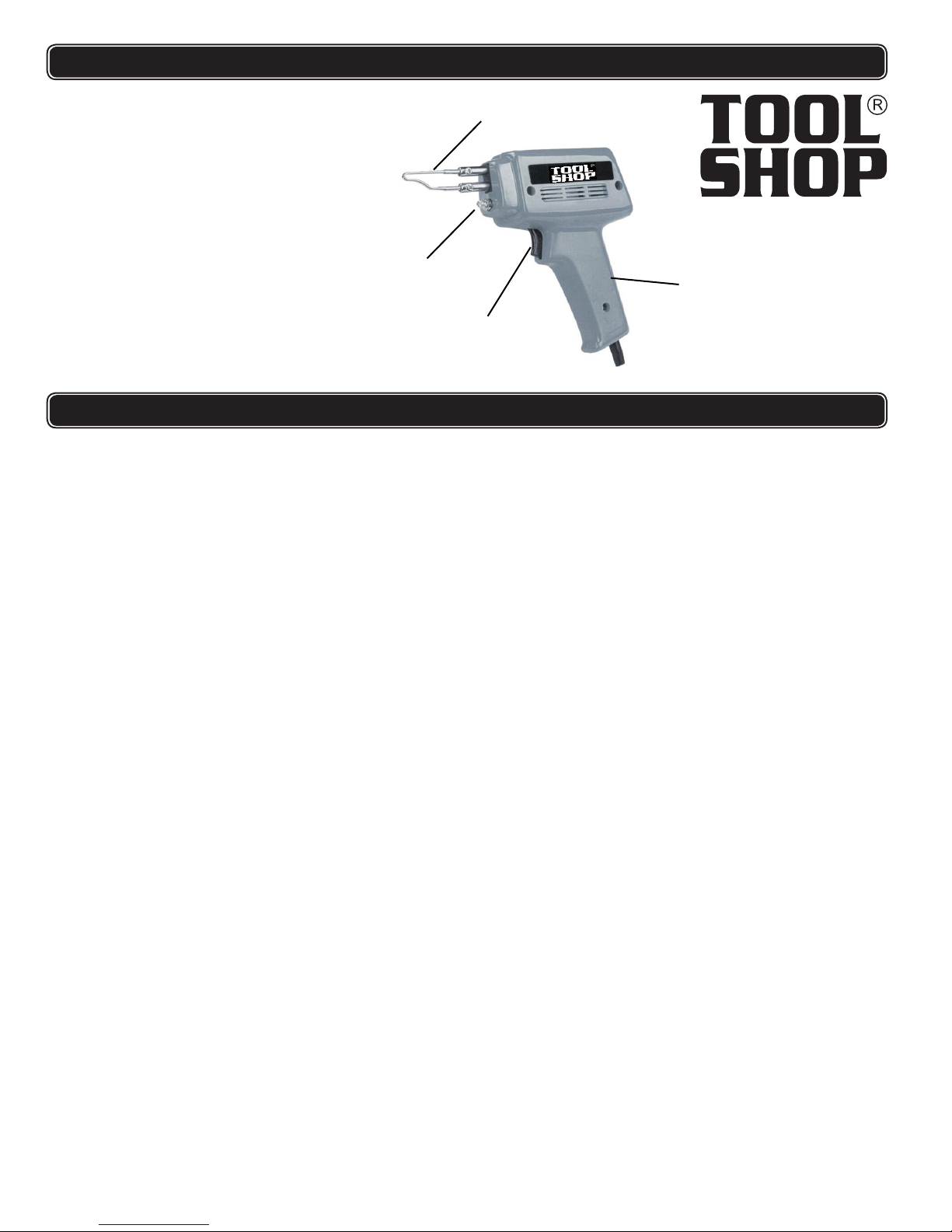
FUNCTION DESCRIPTION
1.Trigger Switch
Soldering Tip
2.
3. LLight
4. Handle
TING PROCEDURES
3
2
1
OPERATING PROCEDURES
Preparing the Soldering Tip
1. Using a screwdriver, check that the Soldering Tip Nuts are not loose.
Do not overtighten as you may strip the threads.
2. Set the Soldering Gun on the workbench, and plug the Line Cord into an electrical
outlet.
4
3. Press on the Trigger Switch until the Soldering Tip heats up.
4. Apply a sufficient amount of rosin-core solder to melt over the entire tip of the
Soldering Gun.
Preparing the Metal to be Soldered
1. If wires are to be soldered, thoroughly clean or scrape the wires so that only the
clean copper is showing. Carefully splice the wires to prepare for solder.
2. If other metals are to be soldered, thoroughly clean or scrape the metal surfaces. It
may be necessary to apply acid flux (not supplied) to those metal surfaces before
soldering.
Soldering
1. Press on the Trigger Switch until the Soldering Tip heats up.
2. Brush on solder flux, as needed, to the workpiece. Place the Soldering Tip to the
joint, wiring splice, or metal to be soldered.
3. Apply solder to the wire splice or metal to be soldered, not the Soldering Tip.
When the splice or metal is hot enough, it will melt the solder causing it to flow
within the splice or between the metal surfaces.
4. When the solder has flowed over the entire wire splice or metal surface, remove the
Soldering Tip and release the Trigger Switch.
If you are new to soldering, you may find it helpful to practice soldering first on scrap
wires and splices.
4
Page 5

MAINTENANCE
ADJUSTMENTS
Note: Maintenance requiring disassembly of this tool should only be performed while
the product is disconnected from the electrical supply circuit and give sufficient
time to cool down.
1. When you are finished soldering, heat up the Soldering Tip (1) again and apply a
small amount of rosin-core solder to coat the tip. Wipe off with a rag.
This will leave the tip clean and ready for use again.
2. If the Soldering Tip cracks or becomes eroded, the Soldering Tip needs to be
replaced. In this condition, it will not heat or perform properly.
Accessories
Replacing the Soldering Tip
1. To replace the Soldering Tip, place the Screwdriver over each nut and remove
by turning counterclockwise.
2. Push the nuts toward the Soldering Tip end, exposing the opposite ends of the
Soldering Tip.
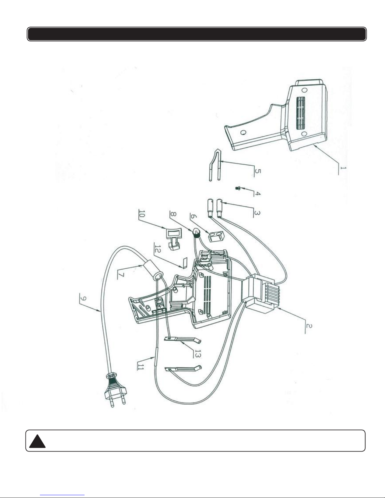
3. Guide the old Soldering Tip out of the Transformer Assembly mounting posts .
Refer to the Assembly Drawing on the next page.
4. Straighten out the ends of the old Soldering Tip using pliers, and remove the Nuts.
5. Place the Nuts over the mounting ends of the new Soldering Tip.
6. Using pliers slightly, bend the mounting ends of the new Soldering Tip for added support
from the connectors.
If the bend is too long, the Nuts will not fit over mounting posts.
7. Guide the bent ends into the mounting posts of the Transformer Assembly.
8. Carefully tighten the Nuts over the mounting posts.
Make sure that the Nuts fit squarely over the threads or damage will occur to the
mounting post threads. Do not overtighten.
Replacing the Light Bulb
1. Remove the Light Bulb Lens from the front of the Soldering Gun.
2. Pull out the burnt Light Bulb and replace with a new one of the same voltage and
type (see Specifications).
3. Replace the Light Bulb Lens
5
Page 6

PARTS LIST
}
ADJUSTMENTS
1
2
3
4
5
6 1
7
8
9 1
10
11 1
12
13
Body
Transformer
Connectors
Screw
Soldering Tip
Connector Holder
Cable Strain Relief
Light Bulb
Power Cord
Trigger Switch
Electrical Connection Cover
Spring Lever
Connecting Rods
1
1
2
2
1
1
1
1
1
2
6
Page 7
SCHEMATIC DRAWING
!
WARNING Repairs should be made by an authorized repair center. Do not
open or disassemble
for questions regarding this power tool.
this power tool
. Contact at
1-866-915-8626
7
 Loading...