

Page 1
241-9023
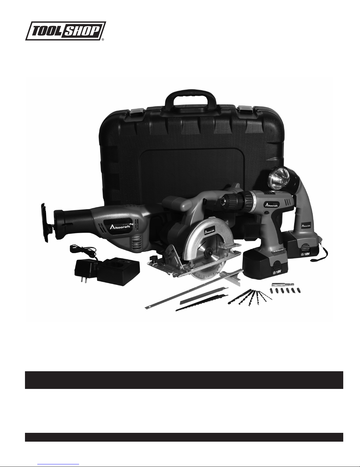
18VOLT CORDLESS 4-PIECE COMBO KIT
You will need this manual for safety instructions, operating procedures and warranty.
Put it and the original sales receipt in a safe dry place for future reference.
Operator’s Manual
SAVE THIS MANUAL
Page 2

IMPORTANT SAFETY INSTRUCTIONS
WARNING:
precautions should always be followed to reduce the risk of fire, electric
shock, and personal injury.
When using electric tools, machines or equipment, basic safety
READ ALL INSTRUCTIONS BEFORE USING THIS TOOL
1. KEEP WORK AREA CLEAN. Cluttered areas can cause injuries.
2. CONSIDER WORK AREA ENVIRONMENT.
wet, or poorly lit locations. Don’t expose tools to the rain. Keep the work area
well lit. Don’t use tools in the presence of flammable gases or liquids.
3. KEEP CHILDREN AWAY.
Don’t let them handle machines, tools or extensions cords.
4. STORE IDLE EQUIPMENT.
Equipment also should be in a high location or locked up to keep out of reach
of children.
5. DON’T FORCE THE TOOL. It will do the job better and more safely at the rate
for which it was intended.
6. USE THE RIGHT TOOL.
of a larger industrial tool. Don’t use a tool for a purpose for which it was not
intended.
7. DRESS PROPERLY.
in moving parts. Protective, non-electrically conductive
footwear are recommended when working. Wear protective hair covering to
contain long hair and keep yourself from harm.
8. USE EYE PROTECTION.
produces metal filings, dust or wood chips.
situations. Wear a clean dust mask if the work involves creating a lot of fine or
coarse dust.
9. DO NOT TOUCH BITS OR BLADES WITH HANDS AFTER USE. They can
become extremely hot after job is completed.
10. SECURE WORK.
than using your hands and it frees both hands to operate the tool.
11. DON’T OVERREACH.
reach over or across machines which are running.
12. MAINTAIN TOOLS WITH CARE.
safer performance. Follow instructions for lubricating and safe performance.
Follow instructions for lubricating and changing accessories. Keep handles dry
clean and free from oil and grease.
13. REMOVE ADJUSTING KEYS AND WRENCHES.
keys and adjusting wrenches are removed from any rotating tool before using.
14. AVOID UNINTENTIONAL STARTING.
switch. Be sure the direction switch is in the
use or when changing attachments.
15. STAY ALERT.
any tool when you are tired.
16. CHECK FOR DAMAGED PARTS.
should be carefully checked to determine that it will operate properly and
perform its intended function. Check for alignment of moving parts, binding
of moving parts, breakage of parts, mountings, and other conditions that may
affect its operation. Check bits and blades to make sure they are sharp and
not chipped. Inspect screws and tighten any ones that are loose.
is damaged should be properly repaired or replaced by an authorized service
center unless otherwise indicated elsewhere in the instruction manual. Have
defective switches replaced by an authorized service center.
Don’t use the tool if switch does not turn on and off properly.
17. GUARD AGAINST ELECTRIC SHOCK.
surfaces: pipes, radiators, ranges, and refrigerator enclosures. When
drilling or cutting into walls, floors, or wherever “live” electrical wires may be
encountered, try to ascertain whether there is a danger of shock. Even so, DO
NOT TOUCH THE CHUCK OR ANY FRONT METAL PARTS OF THE TOOL.
Hold the tool only by the plastic handle or the side grip to prevent electric shock
if you hit a live wire.
REPLACEMENT PARTS. When servicing, use only identical replacement parts.
18.
2
Use clamps or a vise to hold the work if possible. It’s safer
Watch what you are doing & use common sense. Don’t operate
All children should be kept away from the work area.
Store equipment in a dry area to inhibit rust.
Don’t force a small tool or attachment to do the work
Don’t wear loose clothing or jewelry, they can be caught
Use a full face mask if the work you’re doing
Keep proper footing and balance at all times. Do not
Keep tools sharp and clean for better and
Before using tool, any part that is damaged
Don’t use power tools in damp,
gloves and non-skid
Goggles are acceptable in other
Make it a habit to check that
Don’t carry tools with a finger on the
STOP
position when not in
Any part that
Prevent body contact with grounded
!
,
Page 3
PRECAUTION FOR BATTERY AND CHARGER
!
!
CHARGE BATTERY AT LEAST 6 HOURS before initial use.
CHARGE AT ROOM TEMPERATURE.
1.
°F.
°F and lower than 1
2
3
2. DO NOT CHARGE IF CHARGER’S CORD OR PLUG IS DAMAGED. Charg-
ing with damaged cord may result in re or electrical shock. If charger is dam
aged in any way, have it repaired by a qualied serviceman.
DO NOT CAUSE A SHORT IN THE BATTERY TERMIANLS.
3.
metal such as paper clips, nails, the sides of a metal tool box do not cause a
short in your battery.
4. DO NOT INCINERATE BATTERY
WARNING!
The warnings, cautions, and instructions detailed in this manual can not
cover all possible conditions and situations that occur.
USE COMMON SENSE AND CAUTION WHEN OPERATING THE TOOL.
22
Extremely
high temperatures and re can result.
The temperature must be higher than
Take care that
-
SPECIFICATIONS
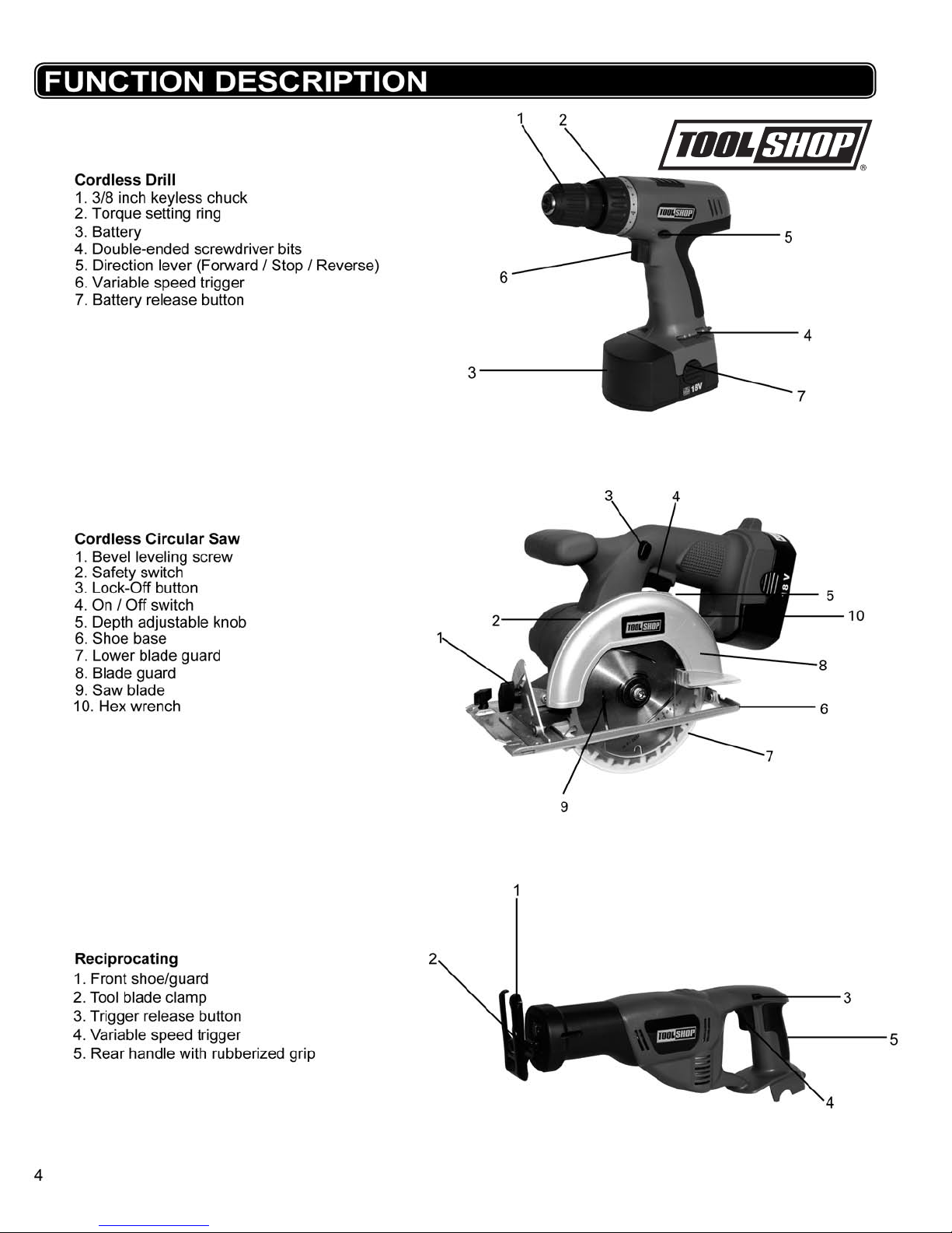
Cordless Drill
3/8 inch Keyless chuck
20 Torque setting plus drill setting
Voltage:18 volts DC
Variable speed 0-600RPM,Reversible
2 double-ended screwdriver bits
(stored in clips on the drill handle)
Cordless Reciprocating saw
Voltage:18 volts DC
3000 SPM
No load speed: 0
Stroke:7/8 inch
2 Reciprocating Blades:1 for wood,1 for steel
1 wrench
Circular Saw
Voltage:18 volts DC
No load speed:
Rip guide
5-1/2 inch blade- 24T one pass
1 hex wrench
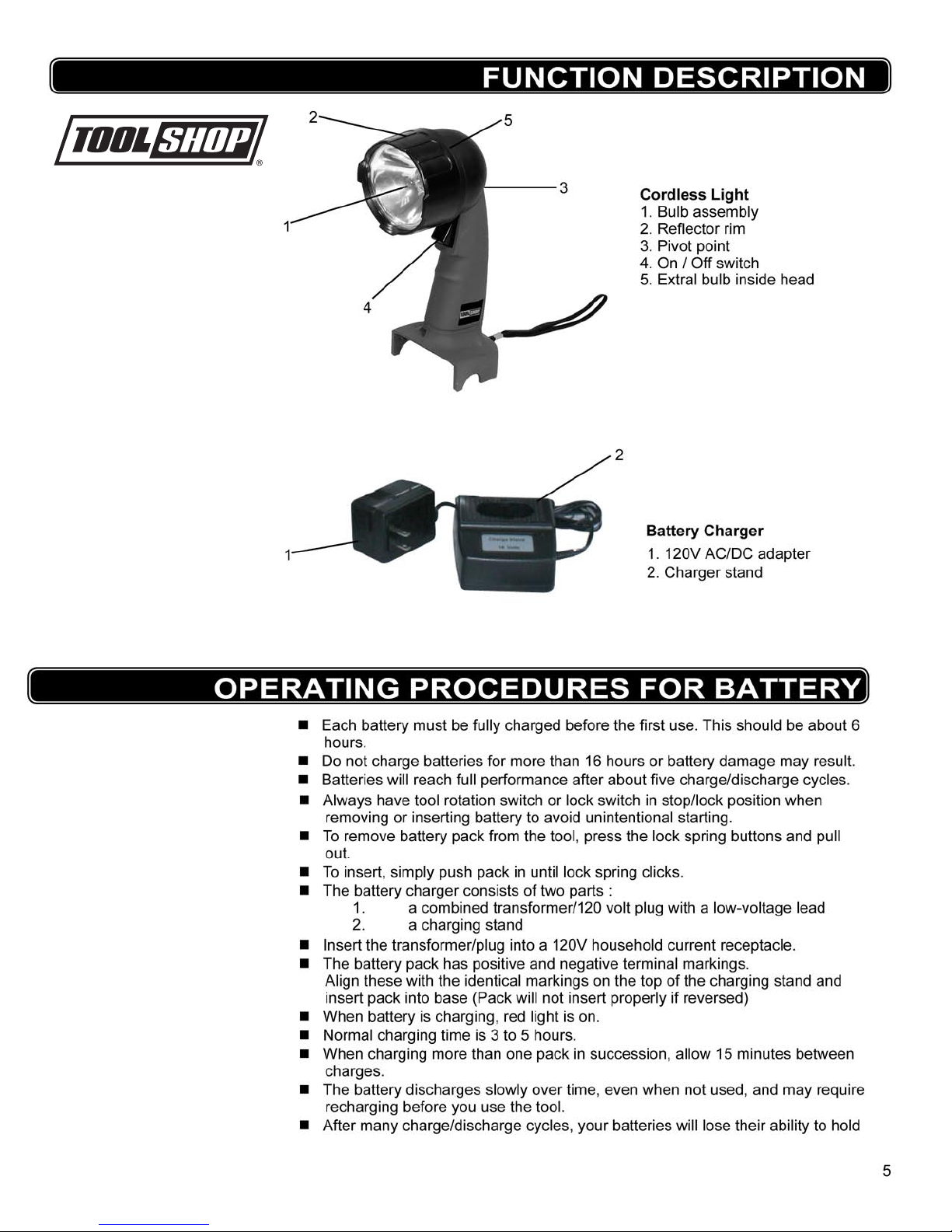
Cordless Ligh
Voltage: 18 volts DC
Bulb:
10 Watt
S
wivel head
extra bulb stored inside head
1
Charger
Charging time: 3-5 Hours
C-UL-us Approved
-
28
00RPM
t
AC/DC Adapter
Two Batteries
Voltage: 18 volts DC
1200mAh Ni-Cd Rechargeable
3
Page 4
Page 5
Page 6
OPERATING PROCEDURES FOR BATTERY PACK
a charge. They should then be replaced. Dispose of batteries at an appropri
ate waste disposal facility. They contain cadmium, so do not throw batteries
away in common trash receptacles.
Charge battery 6 hours every 3 month if you do not use it, as battery will discharge
slowly over time.
Please unplug the ac/dc adapter after battery charged, the charger and AC/DC
adapter may be damaged if pluged into a 120v outlet continuously for 24 hours.
WARNING! Never charge the battery before it has cooled down, charging a hot battery may
cuase the battery to explode.
WARNING!
contain cadmium, so do not throw batteries away in common trash
receptacles.
Dispose of batteries at an appropriate waste disposal facility. They
-
OPERATING PROCEDURES FOR DRILL
Rotation Direction
Your drill is equipped with a 3-position forward/stop/reverse switch through the housing
above the trigger.
When it is pushed toward the right, rotation is forward (clockwise).
When pushed in from the right to the left side, rotation is reversed (counter-clock
wise)
When in center position, it is locked in neutral and the trigger is blocked. Do not
push the rotation direction switch until the chuck stops turning.
-
!
!
Torque Regulator
This is a 20-position dial situated just before the chuck.
When dial indicator reads 1, torque is at minimum before the clutch disengages
the chuck from the drive; when indicator is just past 20, output is at maximum
before it is disengaged.
This is useful in driving screws into different types of material. More torque will set
a screw deeper into material; less torque will prevent it stripping and also pre
vents excessive battery drain. Larger screws require more torque to drive than
small ones. A little trial and error will show you which is the optimum setting for
the situation.
Release the trigger when the clicking sound indicates the chuck will not turn fur
ther.
For drilling, always use the drill setting, indicated by a drill bit.
drive does not disengage from the chuck.
-
-
At this setting, the
Keyless Chuck
1. Center the rotation direction switch to prevent the motor accidentally starting.
2. Note there are two rings on the chuck. Turning the endmost knurled ring of the
chuck clockwise by hand while with the other hand, holding the second ring
(closer to the rear of the tool) to prevent the motor turning; closes the jaws of
the chuck. Turning that same endmost knurled ring counter-clockwise opens the
jaws.
3. Open the jaws to accept a bit and then close the jaws so they clamp the bit
tightly.
6
Page 7
OPERATING PROCEDURES FOR RECIPROCATING SAW
Before installing or removing saw blade remove battery pack.
!
!
!
WARNING
Installing a saw blade:
1. Using the hex key stored in the right side of the housing in front of the
handle, loosen the hex screw on the saw blade clamp.
2. Insert the blade into the blade clamp. Make sure that the saw teeth are
ALWAYS
3. Align the hole in the shank of the blade and the blade clamp with the pin in
4. Tighten the hex screw rmly, to secure the blade.
WARNING: Before you insert battery pack, always pull on the blade sharply to
ensure it is rmly held in the blade clamp. Failure to do so may result in serious
injury.
RUNNING THE RECIPROCATING SAW
1.
Hold the tool rmly. Check to make sure that saw blade travel is not ob
2.
TYPES OF CUTTING
Blade Selection: To obtain the best performance from your saw it is important to
select a specic blade for the particular application and type of material you wish
to cut. By doing this you will get a smoother faster cut and prolong blade life.
:
facing down.
the saw bar, rmly press the pin against the saw bar.
structed. From either the left or the right, push in and hold the trigger
lock release button located above the trigger. Squeeze the trigger switch.
Squeezing the trigger more will increase the speed.
Once the trigger switch is depressed, you can release the button.
WARNING:
!
!
reaches its maximum speed set on the Variable Speed Dial. Failure to comply
could cause loss of control and result in serious injury.
NOTE: Make sure that you do not hit any electrical wires, gas, or water pipes.
Check the wall with a pipe/cable detector before you cut
General Cutting
Hold your saw rmly in front and away from you. Make sure the blade is
clear of any surface. Be sure the material to be cut is held rmly
pieces should be clamped in place to a workbench. Mark the line of cut
clearly. Press the trigger lock release. Pull the trigger switch. Set the shoe
against the workpiece. Allow the blade to cut the material. Do not force it.
Use only enough pressure to keep the saw cutting.
Metal Cutting
Use a sharp blade especially designed to cut the material you are work-
ing with. It is recommended you use a cutting uid on the metal surface to
avoid heat build up. When cutting metallic material with this tool, be sure to
us a ne tooth blade. To ensure safe operation, adjust the motor speed to a
slower setting.
Wood Cutting
When cutting wood material with this tool, it is recommended to use a
coarse tooth blade.
Make sure the blade does not touch the workpiece until the saw
OPERATING PROCEDURES FOR CIRCULAR SAW
. Small
WARNING
serious problems if:
Moving parts get stuck
Speed drops to an abnormally low level
The motor housing gets hot
Sparks or odours emit from the casing
: Turn off your saw at once, remove the battery and inspect it for
!
7
Page 8
OPERATING PROCEDURES FOR CIRCULAR SAW
Do not put hands directly in front of, behind, or below the saw blade
CAUTION:
when cutting.
1. Always grasp the saw with both hands on the handles and push the saw
through the material.
2. Be sure there are no nails or any other foreign objects in or on the work piece,
or in the path of the blade. They could cause damage to the saw blade, injury
from kickback or even injury from flying debris.
3. Make sure the work piece is properly supported at all times. Work piece should be
properly supported during the cut.
4. Whenever possible, secure the work piece with clamps or in a vise. Do not
hold short pieces by hand while cutting.
5. When making cuts parallel to existing straight edges, whenever possible, insert
the rip fence into the slots at the front of the saw. Fasten it in place at the de
sired distance, with the screw clamp provided, and use it to help keep the cut
as straight and parallel as possible.
6. Make sure you are fully prepared to begin your cut before squeezing the trigger
switch. Mark the line of cut clearly.
7. Set the shoe plate against the work piece.
8. Hold the tool firmly. Motor torque will cause the tool to twist, so a firm grip is im
perative. Check to make sure that saw blade travel is not obstructed. Squeeze
the trigger switch.
9. Allow the saw blade to reach full speed before pushing it into the work piece.
10. Do not force the saw blade into the work piece. Apply moderate pressure, al
lowing the blade to cut without being forced.
11. This tool is designed to make straight cuts only. Do not attempt to cut curves
with it. Twisting the saw to either side while cutting will cause the blade to bind
in the work piece, perhaps causing kickback, personal injury, damage to the
work piece, and /or damage to the saw.
12. If it becomes necessary to back out of an incomplete cut, turn of
13. To turn off the saw, release pressure on the Trigger Switch. Always allow the
blade to come to a stop before putting the tool down.
Changing the Blade
WARNING:
blade changing to avoid accidental starting.
-
-
-
f the saw.
Please remove the battery from the circular saw before doing any maintenance or
!
!
1. Press and hold the arbor lock button just to the right of the blade guard at the
front of the saw.
2. Use the hex wrench that is included with the kit.
3. The arbor screw has a left-handed(reverse)thread and it turns backwards. Turn it
clockwise to loosen.
4. Remove the flange and blade.
5. Replace with the new blade.
6. Place the flange and screw back on.
7. Turn counter-clockwise to tighten.
Cutting Depth Adjustment
1. REMOVE battery pack fi rst.
2. Hold the saw fi
knob and move shoe to obtain the desired depth of cut.
3. Make sure the depth adjustment knob has been retightened (clockwise)
before operating the saw.
Bevel Angle Adjustment
The full range of the bevel adjustment is from 0° to 50°. The quadrant is
graduated in increments of 5°. On the front of the saw is a bevel angle
adjustment mechanism, consisting of a calibrated quadrant and a knob. To set
the saw for a bevel cut:
1. REMOVE battery pack fi
2. Loosen (counter clockwise) the quadrant knob adjust the base to the desired
angle mark. Re-tighten knob fi rmly (clockwise).
8
rmly and loosen (counter clockwise) the depth adjustment
rst.
Page 9

OPERATING PROCEDURES FOR LIGHT
ON/OFF
To turn the worklight ON, simply slide the ON/OFF switch forward. To turn the
worklight OFF, simply slide the ON/OFF switch backward.
TO SWIVEL THE WORKLIGHT
To swivel the head of the worklight, hold the worklight with two hands. One
1.
hand should be around the body of the light; the other hand should be
around the head of the worklight.
2. Using the hand that is holding the head of the worklight, twist the head clockwise. Continue to adjust the light until it is adjusted to the angle that works for
your job.
To return the worklight to its original position, twist the worklight in a counter-
3.
clockwise direction.
TO REPLACE THE LIGHT BULB
To change the light bulb, hold the top of the light with one hand and the rim of the
worklight with the other. Using the hand that is holding the rim of the worklight,
begin turning it in a counter-clockwise direction. Continue to turn the rim until
it separates from the body of the worklight. Use care when doing this to avoid
damaging the reector or the protective lens over the worklight. The burnt out
bulb should be removed and discarded appropriately. Replace the bulb and
carefully align the rim and light assembly with the worklight body. Begin twisting
the rim in a clockwise direction.
WARNING FOR OBSTRUCTED MACHINE
WARNING
If this tool becomes obstructed/jammed release the trigger switch immediately
as just a few seconds could cause motor damage.
:
MAINTENANCE
Keep the tools clean using a soft damp (not wet) cloth. Do not use solvents on
the plastic parts.
Lubrication is not necessary. After long use, have an authorized service center
maintain and lubricate the tool.
Should the drill chuck require replacement,
1. Remove the battery pack
2. Open the chuck jaws as widely as possible so you can get at the chuck retain
ing screw.
3. Unscrew the chuck retaining screw with a phillps screwdriver. Note that this is a
left-hand-threaded screw and you remove it by turning it clockwise.
4. Clamp the shorter arm of a large allen wrench in the chuck, aligning it with the
jaws so they grip three of its six flat sides.
5. Place the drill on a flat surface, and support the chuck with a piece of wood
about 3/8 inch above that surface.
6. Strike the long arm of the wrench with a hammer so that the chuck turns
counter-clockwise and unscrews from the spindle.
This may require a fairly sharp blow.
7. Repeat the process in reverse to install a new chuck.
-
•
To maintain the best performance of your rechargeable NiCd battery, protect
it from overheating, both from overcharging and during storage. Occasionally
charge the battery for 6 hours. The battery may also benefit from a full discharge
from time to time.
9
Page 10
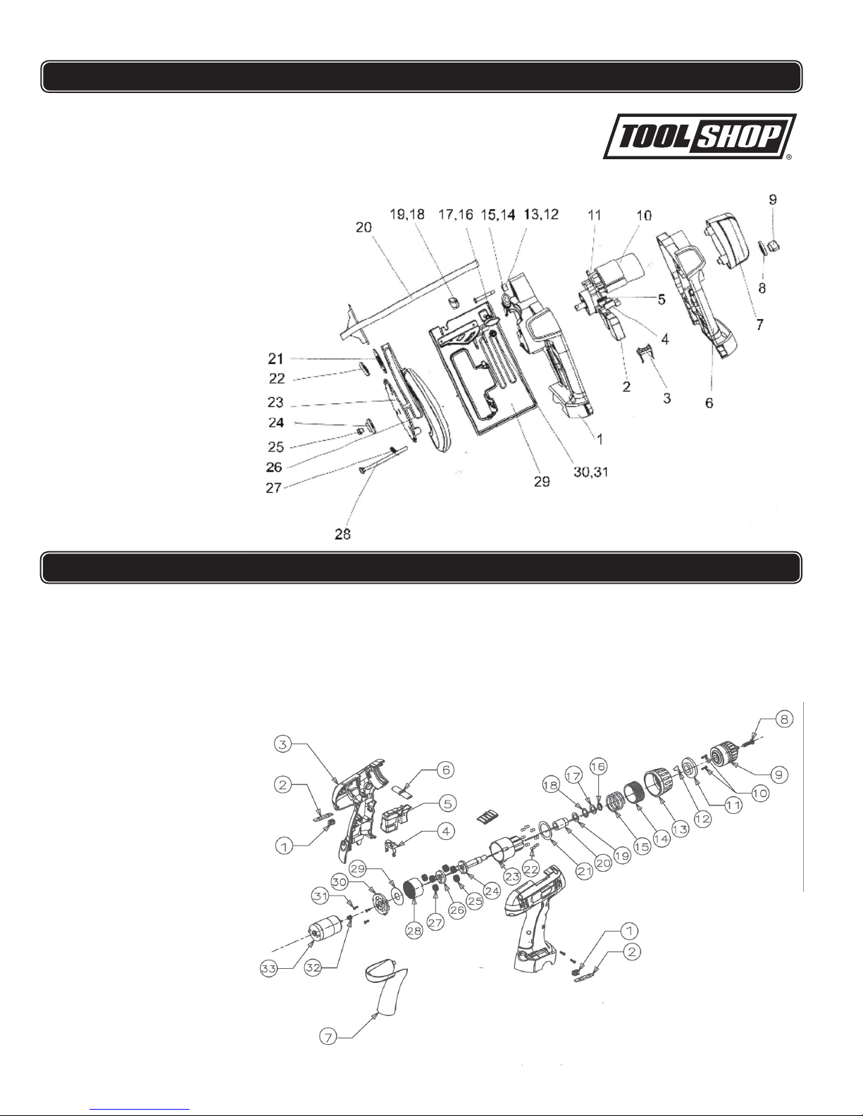
PARTS LIST FOR CIRCULAR SAW
NO. DESCRIPTION
Saw blade
Housing (Left)
1
Switch
2
Battery Clip
3
Switch Lock Button
4
Spring
5
Housing (Right)
6
Motor Cover
7
Washer
8
Plastic nut
9
DC Motor
10
Gear Box
11
Nut
12
Screw
13
Pivot Stop
14
Position Button
15
Plastic Screw
16
Spring
17
Plastic Screw
18
Nut
19
Ruler
20
Fixed Board
21
Flange
22
23
Flange
24
Screw
25
Movable Guard
26
Spring
27
Screw
28
Guide Plate
29
Screw
30
Nut
31
PARTS LIST FOR CORDLESS DRILL
NO. DESCRIPTION
27
1
Screwdriver bit clip
2
Double-ended screwdriver bit
3
Housing(left)
4
Battery cli
5
Trigger switc
6
Forward/reverse butto
Soft handle
7
8
Chuck retaining screw
9
Chuc
10
Screw
1
1
Washe
12
Washe
13
Torque setting ring
14
Ring
15
Spring
16
Snap rin
17
Washer
18
Steel ball
19
Washer
20
Bearing
21
Washer
22 Steel ball
23 Gear box
24 Shaft
25 Planet gear
26 Star gear
p
h
k
s
r
r
g
Planet gear
Inner gear
28
29
Washe
30
Gear box cover
31
Screw
Motor gea
32
33
D.C. motor
r
s
r
10
Page 11
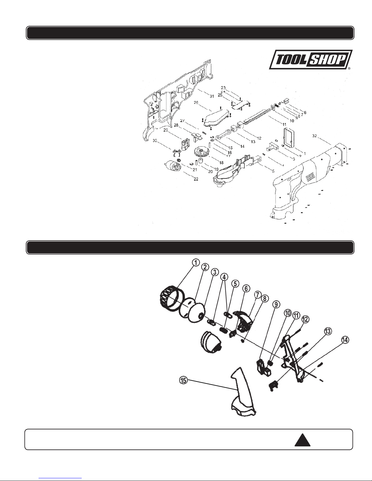
11
NO. DESCRIPTION
1,2,3
4
5
6
7
8
9
10
11
12
13
14
15
16
17
18
19
20
21
22
23
24
25
26
27
28
29
Bracket
Screw
Gear box
Blade holder
Pin
Spring washer
Screw
Bushing
Shaft
Bushing
Bushing
Link Plate
Circlip
Washer
Pin
Gear
Bearing
Pin
Gear
Motor
Screw
Spring washer
Plate
Cover
Sping
Safety release
Switch
PARTS LIST FOR
30
31
32
Battery clip
Housing (A)
Housing (B)
RECIPROCATING SAW
NO. DESCRIPTION
1 Lamp shade
2 Lens
3 Lamp refl ector
4 Bulb
5 Cathode spring
6 Lamp bracket
7 Lamp enclosure
8 Anode spring
9 ABS plectrum
10 Switch
11 Spring
12 Screw
13 Battery clip
14 Housing A
15 Housing B
PARTS LIST FOR CORDLESS LIGHT
WARNING Repairs should be made by an authorized repair center. Do not
open or disassemble
this power tool
for questions regarding this power tool.
. Contact at
1-866-915-8626
!
Page 12

TOOL SHOP®
1-YEAR LIMITED WARRANTY:
4PC 18V CORDLESS TOOL SET
WARRANTY
This
TOOL SHOP®
original purchaser.
brand power tool carries a 1-Year Limited Warranty to the
If the tool fails within one (1) year from the date of
purchase, simply bring this tool with your original sales receipt back to your
nearest
MENARDS
have the tool replaced with the same or similar
retail store. At its discretion,
®
TOOL SHOP®
TOOL SHOP®
agrees to
product free of
charge, within the stated warranty period, when returned by the original
purchaser with or
iginal sales receipt. Notwithstanding the foregoing, this
limited warranty does not cover any damage that has resulted from abuse or
misuse of the Merchandise. This warranty: (1) excludes expendable parts
including but not limited to blades, belts, bits, light bulbs, and/or batteries; (2)
shall be void if this tool is used for commercial and/or rental purposes; and (3)
does not cover any losses, injuries to persons/property or costs. This
warranty does give you specific legal rights and you may have other rights,
which vary
from state to state. Be careful, tools are dangerous if improperly
used or maintained. Seller’s employees are not qualified to advise you on the
use of this Merchandise. Any oral representation(s) made will not be binding
on seller or its employees. The rights under this limited warranty are to the
original purchaser of the Merchandise and may not be transferred to any
subsequent owner. This limited warranty is in lieu of all warranties,
expressed or implied including warranties or merchantability and fitness for a
particular pu
rpose. Seller shall not be liable for any special, incidental, or
consequential damages. The sole exclusive remedy against the seller will be
for the replacement of any defects as provided herein, as long as the seller is
willing or able to replace this product or is willing to refund the purchase price
as provided above.
For insurance purposes, seller is not allowed to
demonstrate any of these power tools for you.
For questions / comments, technical assistance or repair parts –
Please call toll free at: 1-866-915-8626
SAVE
YOUR RECEIPTS.
THIS WARRANTY IS VOID WITHOUT THEM.
(M-F 8am – 5pm EST)
 Loading...