

Page 1
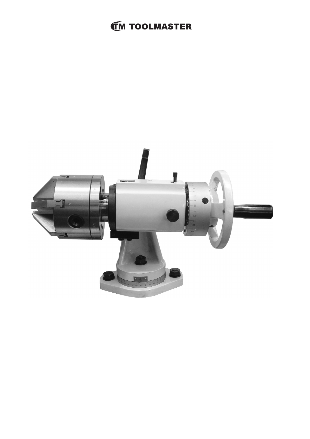
DRILL GRINDING ATTACHMENT
To suit TM6025Q TOOL AND CUTTER GRINDER
OPERATION’S MANUAL
1
www.machineryhouse.com.au
Page 2
0º
270º
90º
180º
INTRODUCTION
Before grinding any cutters, you must set up the attachment to suit the type of cutter or drill you want to
sharpen.
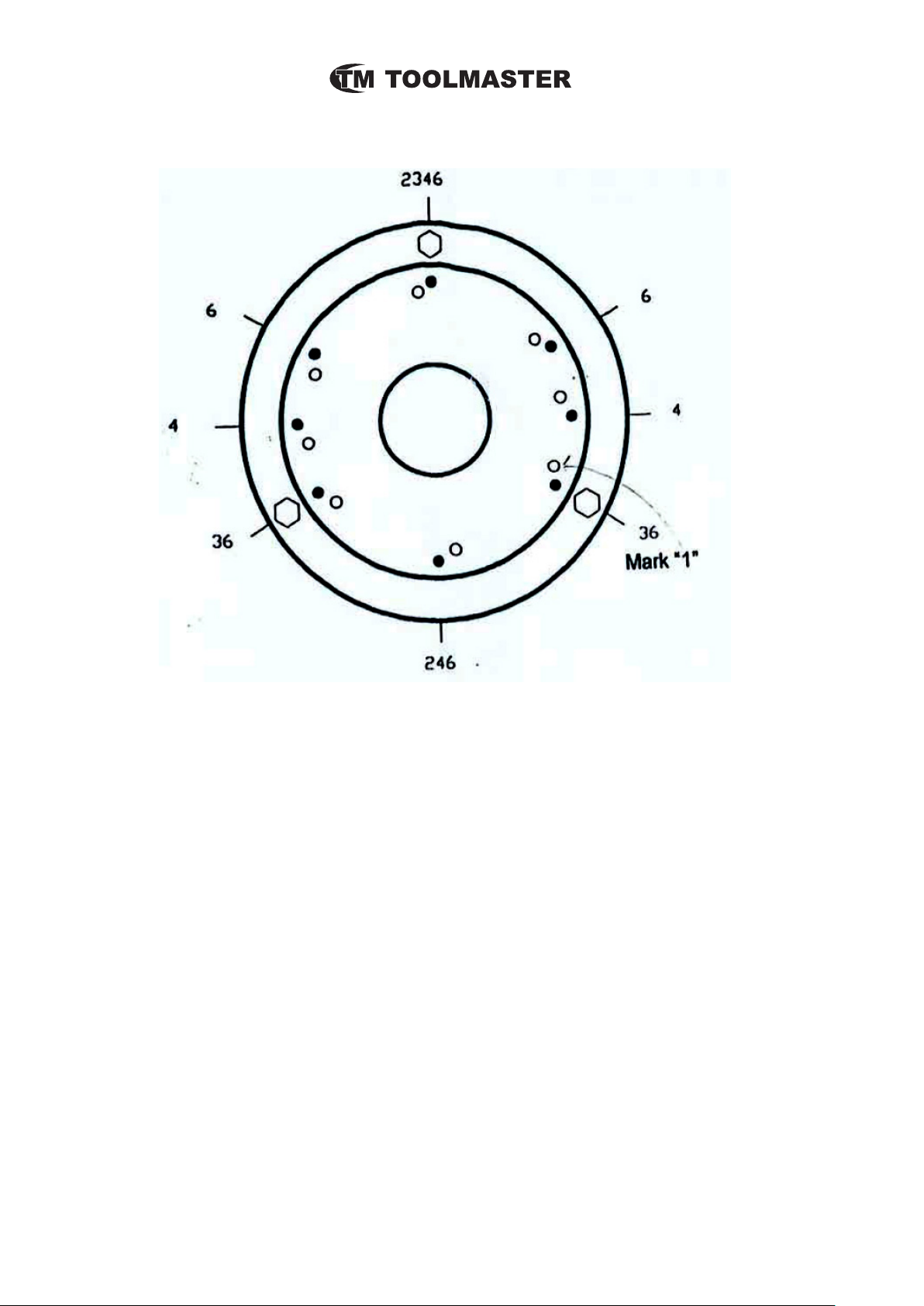
e rst thing to set is the cam pins (No.14), ese are on found on the back of the chuck
e numbers on the above picture show you the position the cam pins (No.14) will need to be placed according to the number of utes of the drill as outlined in the example below.
1. If you would like to grind a standard 2 ute drill, you must screw the cam pins (No.14)into the two
positions marked with a “2”
2. If you would like to grind a tap with 3 utes, you must screw the 3 cam pins (No.14) into the three
positions that are marked with a “3”.
In the above diagram there are two circles of holes an outer circle marked with “l” and inner circle marked
with “¡”
Mark “l”(outside) : Means this is the locations for the cam pins (No 14) to be placed for grinding
drills, step drills, and Taps.
Marls “¡”(inside) ; Means these are the locations for the cam pins (No 14) in for grinding counter
sink drills.
Mark “1” is for grinding the single ute counter sink drills,
2
www.machineryhouse.com.au
Page 3
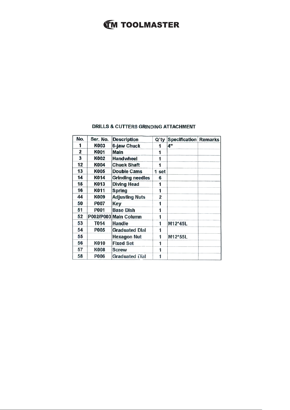
Parts List
3
www.machineryhouse.com.au
Page 4
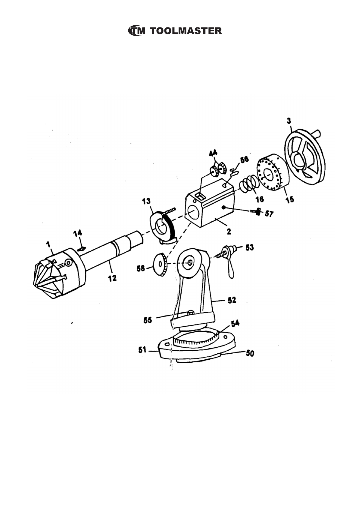
4
www.machineryhouse.com.au
Page 5
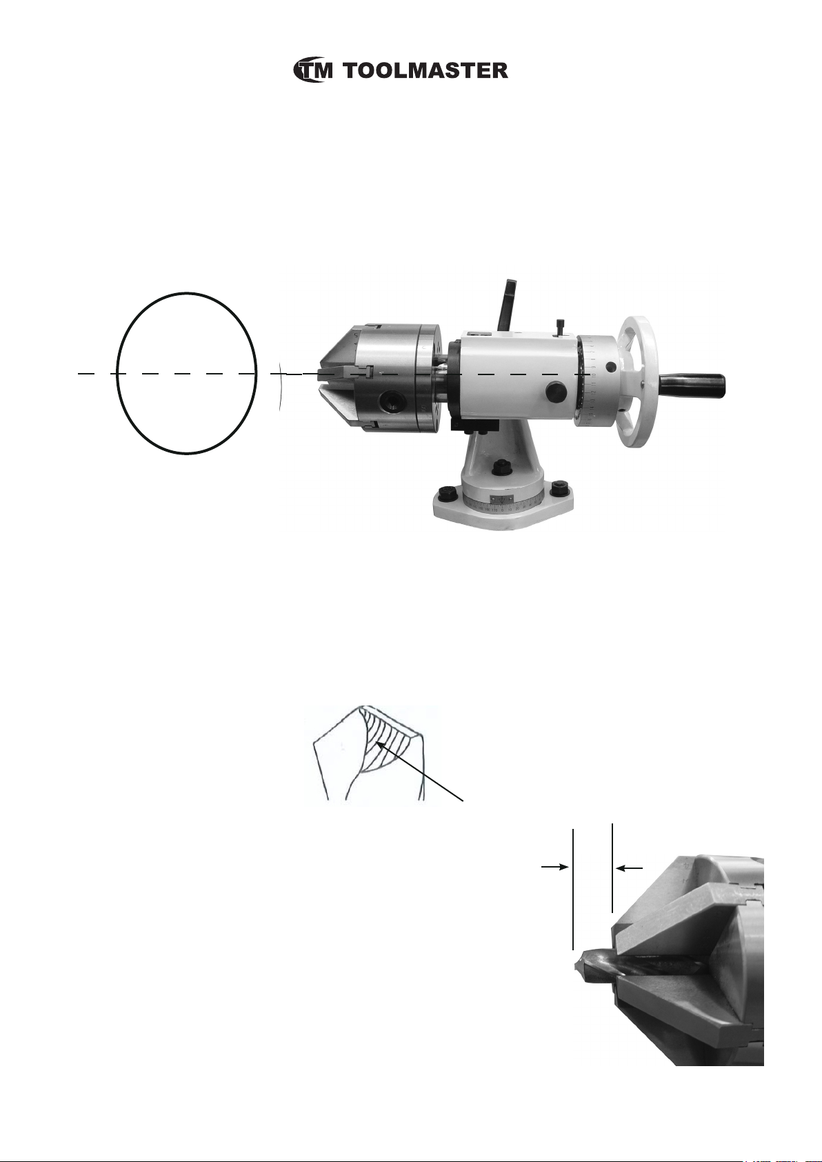
DRILL GRINDING.
1. SETTING UP THE ATTACHMENT
It is important that the attachment is set up correctly on the machine before any operations
are attempted. The Drill grinding attachment should be placed on the table of the machine and be
lined up accurately with the center line of the grinding wheel.
Fig.1
1. GRINDING PREPARATION:
If the drill is badly damaged it may be wise to rst, grind the rear bevel of the drill, This can make
grinding process faster and reduces the chance of excessive heat being applied to the cutting
edge . This will ensure that there is no effect to the hardness and the metal characteristic of the
drill. (see the following gure)
Fig.2
Bevel edge
Fig.3
A. SETTING THE DRILL
10mm-20mm
1.. Insert the drill into the chuck (No.1 ) If the drill is over 6mm it
should protrude 20mm out from the jaws of the chuck. If the drill
is under 6mm, then it should protrude only 10mm out of chuck.
5
www.machineryhouse.com.au
Page 6
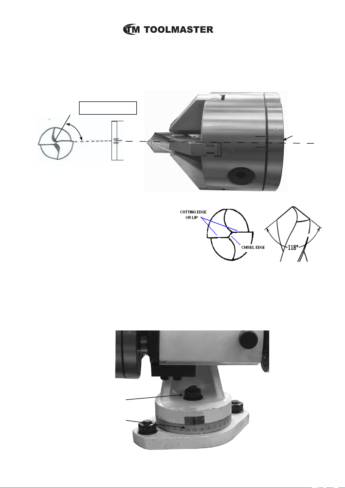
2. To insure that the cam action is align with the cutting edge of the drill, the drill need to be
clamped in the chuck (No1) so that the cutting edge is lined up between the two line marked on
the chuck(No.1) These lines may be faint but can be found by looking for a “0” on the back plate
of the chuck (see the following gure) Once in position then, lock the chuck tightly with the screw
(No.57)
Chisel Edge Angle
Fig.4
B. SET THE CUTTING POINT ANGLE
The cutting point angle of the drill needs to be
selected. The cutting point angle is usually
referred to as an included angle.
There are three drill point angles widely used.
118° angle is used for general purpose drilling of
metal. 135° is used for harder steels and stainless
steel. 114° is used for wood and plastics.
This is the
“0” mark
0
Fig.5
To set the cutting point angle make sure that the attachment is located in the table slot.
Undo the nut (No55) and set the desired angle on the scale (No.54). When you have set the angle then tighten the nut (No.55)
Nut No.55
Scale No.54
Fig.6
6
www.machineryhouse.com.au
Page 7
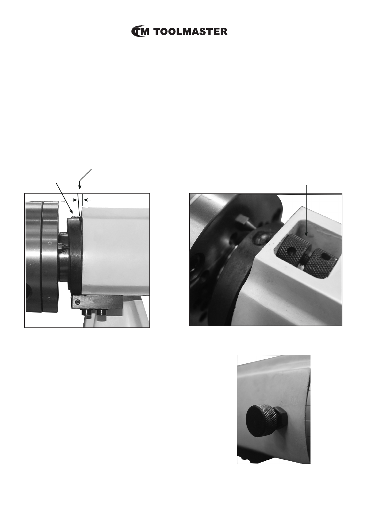
C. SET THE RELIEF ANGLE OF CUTTING POINT (ADJUST LIP CLEARANCE ANGLE)
The relief angle or Lip Clearance, is controlled by the amount of angle given to the cam. (No.13)
The cam is adjustable at one end and is pivoted at the other end. This allows for the cam movement to be varied according to the relief angle desired.
There are two Knurled Lock Nuts (No.44), which can make the cam (No.13) to move back and forward. The more the Cam (No13) moves forward, the larger the lip clearance will be and the more
the Cam (No.13) moves backward, the smaller the Lip clearance or relief will be.
1. Set the amount of cam movement (No13) by adjusting the knurled lock nuts (No44) to set the
relief angle. This function is not graduated but more cam movement means more relief.
This needs to be between
2-6mm for adequate relief
Cam No.13
angle
Knurled Lock Nuts No.44
Fig.7
D. ADJUSTING THE SPINDLE FLOAT
The knurled knob (No.57) can be used to lock the spindle
or can be adjusted to allow the spindle to oat. By adjusting
this knob the amount of spindle end oat or the distance it
can oat can be limited. It should be set so that the cam pins
and cam can interact easily. It should not allow the spindle to
oat more than is require for the cam and cam pins to interact
easily.
7
www.machineryhouse.com.au
Fig.8
Fig.9
Page 8
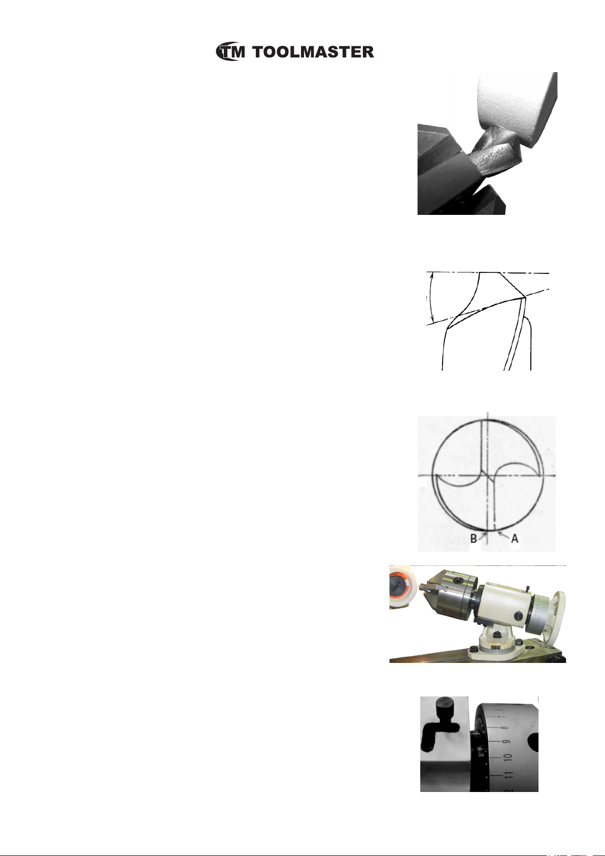
E. PREPARE FOR GRINDING
Move the attachment so that the drill is in the suitable position to the
surface of the grinding wheel.(Fig.10)
1. Turn on the power, and revolve the hand-wheel (No.3) slowly with
one hand. Do not put lateral pressure on the spindle, but allow the
spring (No.16) on the spindle to hold the cam pins against the cam.
2. Keep rotating the hand wheel (No.3) when the grinding wheel
starts and gradually feed the drill towards the wheel until grinding
takes place.
F. GRINDING THE CUTTING EDGE RELIEF ANGLE
The cutting edge is also known as the “LIP” (Fig.11)
The lip relief angle measures the clearance behind the cutting lip.
Move the drill to a suitable position to the surface of the grinding
wheel.
1. Turn on the power, and revolve the hand-wheel (No.3) slowly with
one hand and with the other hand, slowly feed the drill into the wheel
making sure that no lateral pressure is placed on the spindle, so that
the spring (No.16) on the spindle holds the cam pins against the
cam.
2. Continue until both sides of the drill have been restored to the
original state. Be-careful not to overheat the drill
G. SHARPENING THE CUTTING EDGE
In most cases the above operation will be sufcient, but for production
use the second clearance angle may be needed. This is shown by the
distance between “A” and “B” (Fig.12)
1, Loosen Handle (No.53) a little. Then adjust the angle of the xture,
by raising about 10—15° or the angle required. (Fig.13)
2. Now insert the de-tent pin (No.56) into the hole on the cylinder
(No.16) at the rear of the shaft. The drill must be now set using a
height gauge so that the cutting edge is horizontal with the table and in
line with the center line of the wheel..
3. There are two series of matching graduations with holes
around the outside in the cylinder. If the drill has two-uted edges, you must nd the equal positions of the opposite sides of
the cylinder. For example, if you adjust the position to the “6” on
one side, then you must rotate the cylinder to the other “6” of the
other side. This will grind each side evenly and grind the cutting
edge the same on both utes, (Fig.14)
3. Take a light cut across the wheel by using the cross feed
screw then rotate the cylinder and place the indent pin in the opposing number and repeat a light cut. Repeat the process until
there is a small at across the cutting edge.
4, When the grinding procedure has been done or the angle
needs to he changed, move the drill away from the grinding
wheel. This is to avoid the Chuck (No.1) from touching the grinding wheel while No.53 lever is loosened.
Fig.10
Lip or cutting edge relief
angle
Fig.11
Fig.12
Fig.13
8
www.machineryhouse.com.au
Fig.14
Page 9
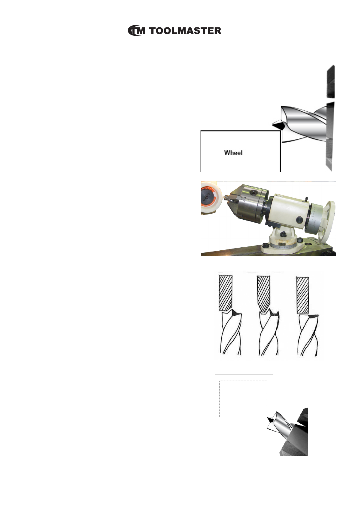
G. SHARPENING A BRAD POINT DRILL (Clearance
angle)
Set up the attachment as in A, B, C
1. Loosen No.55 and align No. 52 about the line of
90°.
2. Loosen No.53, raise the chuck (No.1) about 12°
3, Lock the drill into the chuck (No.1), making sure
you haver aligned the drill correctly between the faint
lines on the chuck.
4. Loosen the knurled nut (No.57) to allow the shaft
to rotate but at the same time not allowing the shaft
to oat more that is needed to operate the cam pins
No.14 against the cam No.13 correctly.
5. While turning the hand-wheel (No.3) move the drill
in towards the wheel. Set the drill to aim for the exter-
nal diameter and the back of the grinding wheel. Start
to grind by rotating the hand-wheel (No.3.) Make sure
the center point is not damaged. (Fig.15)
H. SHARPENING THE CUTTING EDGE
1. Line up the drill cutting edge parallel to the table
and Insert the die-tent pin (No.57) into the hole on
the cylinder (No.15)
3. Loosen handle (No.53) and raise the chuck
(No.1) about 12°.
5. Use the longitudinal feed of the grinding wheel
and the cross feed of the slide rest to control the
feeding of sharpening the cutting edge. After taking a light cut, change to the opposite number of
(No.15) and grind it again until there is a small at
on the cutting edge. Form the wheel to suit the pro-
le desired. (Fig.17)
Fig.15
Fig.16
H. SHARPENING THE CENTRE POINT
1. Line up the drill cutting edge parallel to the table
and Insert the die-tent pin (No.57) into the hole on
the cylinder
3. Loosen handle (No.53) and raise the chuck
(No.1) about 12°.
5. Use the longitudinal feed of the grinding wheel
and the cross feed of the slide rest to control the
feeding of sharpening the cutting edge. After taking
a light cut, change to the opposite number on the
cylinder (No.16) and grind it again until there is a
small at on the cutting edge. (Fig.18)
9
www.machineryhouse.com.au
Fig.17
Fig.18
Page 10
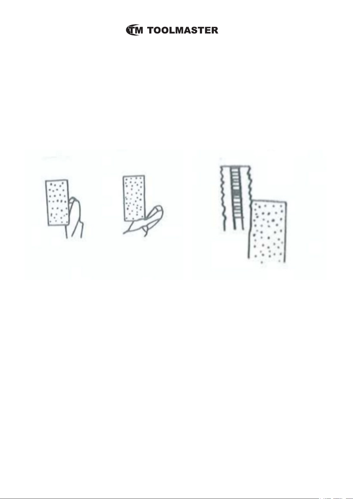
J. GRINDING STEP DRILLS
1. Grinding the step.
a. Lock No.57 into No.12 to allow the shaft to rotate. No.13 does not rotate with the shaft.
b. Push No.12 forward about 10rnm, until half of the screw No.57 sits in the groove in No,12.
This allows the spindle No.12 to turn freely so the step diameter can be ground to size.
(Fig.19)
3.If a second cutting edge has to be ground as the rst layer, the chuck No.1 must be tted
with Cam pins No.14 (two pieces). It is important to align the second cutting edge. After that,
you can nish step drill grinding.
4. Please see the following gure for reference. (Fig.20)
Fig.19
Fig.20
Fig.21
TAP GRINDING
Taps can be found with 2 utes, three-uted edge, four-uted edge, ve-uted edge and six-uted
edge.
2. If equip with three-uted edge tape, then the cam pins need to be changed to another set of
No.14 Cam pins (3 pieces) and insert them into holes marked as “3” in the No.1 chuck. Then,
you can grind the three-uted edge tap as per “F”.
3. If equip with four-uted edge tape, then the cam pins need to be changed to another set of
No.14 Cam pins (4 pieces) and insert them into holes marked as “4” in the No.1 chuck. . Then,
you can grind the four-uted edge tap.
4. Use the same way to grind ve-uted and six-uted edge.
5. Make the forepart of tap feed into the proper position at the surface of grinding wheel.
(see Fig.21)
G, Revolve No.3 slowly by one hand when the grinding wheel starts (remember do not pause),
and then do the feed by the other hand . Keep feeding until the tap touches the grinding wheel
and make sparks,
10
www.machineryhouse.com.au
Page 11
END MILL LIP GRINDING
I . Turn off the grinding machine and loosen No.53 a little, and move the head to the angle you
need for grinding the lip relief angle.
2. Place the de-tent pin No.56 in one of the holes in the cylinder No.16 at the rear of the shaft.
These are used to control the positions of the cutting edges. Set up the cutter with a height gauge
so that the cutting edge or lip is parallel to the table. Then clamp the cutter.
. There are a series of numbers between 0º and 180º. The same series of numbers are in 180º
- 360º. If the end mill has two-utes, you must nd the equal positions in the opposite range. For
example, if you have the die-tent pin in position “6” on one side, then you must rotate the cylinder
No.16 to the position “6” on the opposite side. This method insures each lip is correctly ground
with the edges being the same height.
3. When the grinding procedure has been done, then the angle: needs to be changed, the cutting
edge has to moved so that it clears the grinding wheel. This is to avoid No.l chuck touching the
grinding wheel while No.63 lever was loosened.
4. If you grind the end mill with three-uted edge, you should divide the holes on the cylinder
No.16 into three equal partitions.
5. If you grind the end mill with four-uted edge, you should divide No.16 Into four equal parti-
tions.
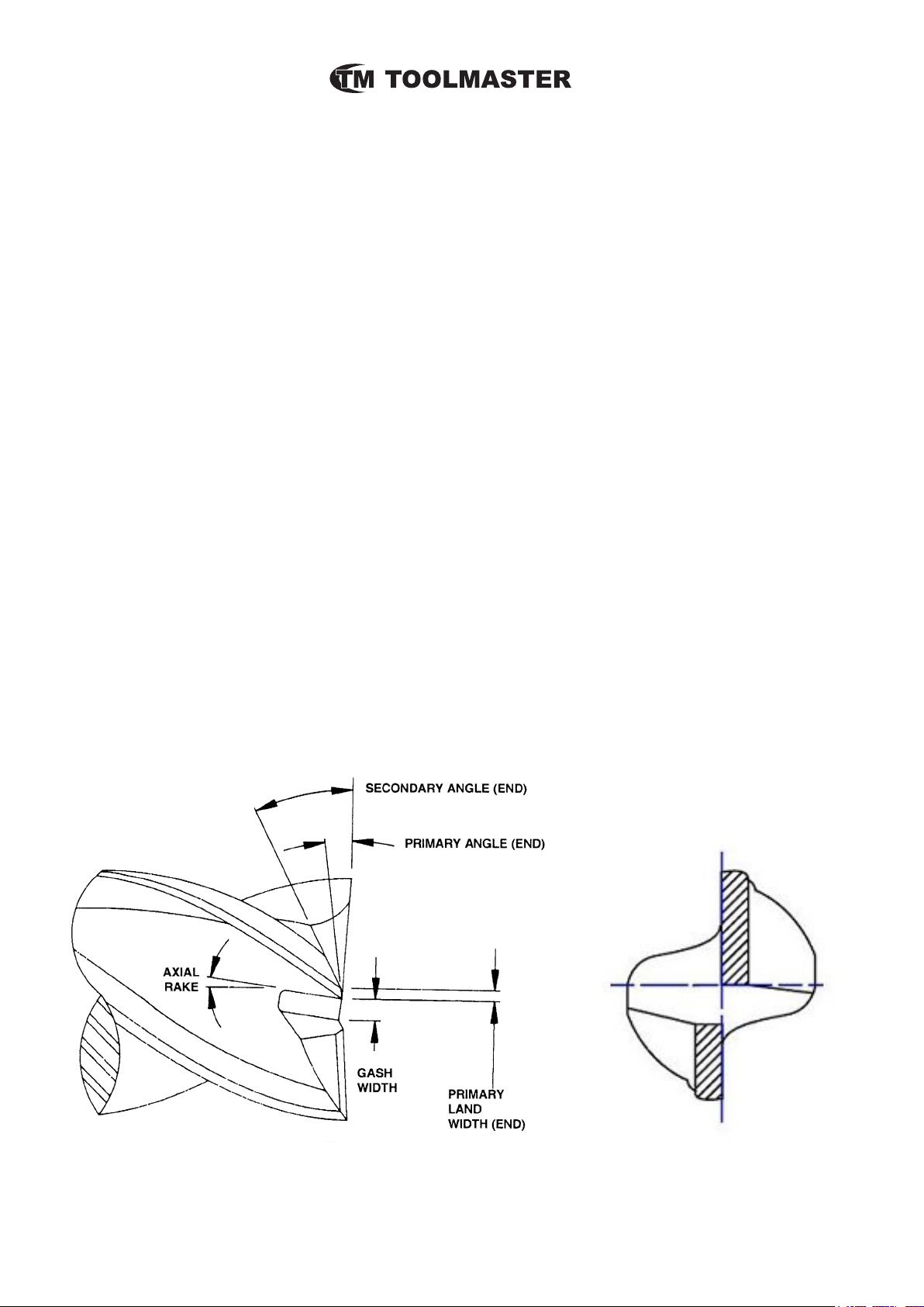
6. The cutting edge of the end mill has two angles.(Fig.22) The angles are the primary angle, and
the secondary angle. A third process is the central gash point. The angles can be changed when-
ever you need by loosening No.53.
7. If the cutter can plunge cut, the only other process may be to relieve the gash width.
A center cut cutter is one where one side of the cutter has its cutting edge to the center with
clearance between the remaining cutting edges. See Fig. 23. This clearance needs to be maintained
11
Fig.22
Fig.23
www.machineryhouse.com.au
 Loading...