

Page 1
Industrial Series
ATN-170
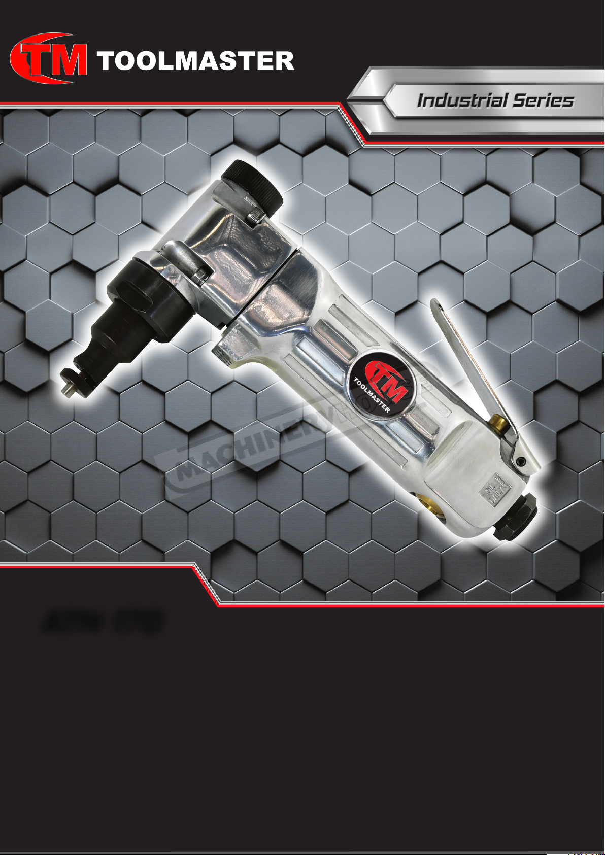
AiR NIBBLER
INSTRUCTION MANUAL
Order Code: A082
www.machineryhouse.com.au www.machineryhouse.co.nz
www.machineryhouse.com.au
www.machineryhouse.co.nz
1
Page 2
Safety Air Tool Warnings
1. Read and understand this entire manual before
attempting assembly or operation.
2. Read and understand all warnings posted on
the tool and in this manual. Failure to comply
with all of these warnings may cause serious
injury.
3. Replace warning labels if they become
obscured or removed.
4. Do not use this tool for other than its intended
use. If used for other purposes, Toolmaster
disclaims any real or implied warranty and
holds itself harmless from any injury that may
result from that use.
5. Always wear approved safety glasses or face
shield while using this tool. (Everyday eye
glasses only have impact resistant lenses; they
are not safety glasses.)
6. Wear ear protectors (plugs or muffs) if the
noise exceeds safe levels.
7. Wear gloves and protective clothing if
operationproducessparksoryingparticles.
Glovesshouldbetight-tting,withoutfrayed
ngersorhangingthreads.Keephandsand
body away from the working area of tool.
13. Adopt a comfortable posture with proper
balance,and maintain secure footing at all
times. Non-slip footwear or anti-skid oor strips
are recommended.
14. Do not wear loose clothing or jewellery. Conne
long hair.
15. Excessive air pressure and too much free
rotation may decrease life of the tool and may
cause a hazardous situation.
16. Check air hoses for wear, and keep them away
from heat and sharp edges. Repair or replace
damaged air hose immediately. Do not carry
tool by the air hose.
17. Air hose may cause tripping hazards; keep hose
away from trafc areas.
18. Do not use this tool near ammable objects, or
in potentially explosive environments. Do not
use near live electrical wires.
19. Do not use power tools in damp or wet location,
or expose them to rain. Keep work area well
lighted.
8. Do not operate an air tool continually at full
throttle without a work load on the tool.
9. The air tool must be properly lubricated
before operating.
10. Never start a percussion type air tool (chipper,
breaker, buster, etc.) without securing the
tooling in the retainer and placing the tip
against the work surface.
11. Do not operate air tool without its guards in
place. Do not modify the tool.
12. Do not operate this tool while tired or under the
inuence of drugs, alcohol, or any medication.
www.machineryhouse.com.au
www.machineryhouse.co.nz
20. Do not leave a connected tool unattended.
When not in use, disconnect tool from air
source.
21. Shut off air supply and discharge any residual
pressure from tool before removing hose,
making adjustments, changing accessories, or
storing tool.
22. Make sure tool is switched off, and your nger
off the trigger, before connecting to air supply.
Remove adjusting keys before operating
24. Keep visitors a safe distance from the work
area. Keep children away.
2
Page 3
Safety Specic For Air Nibbler
1. Ensure the sheet metal is secure and well
supported. Do not hold the workpiece with
your hand.
2. Do not attach the air hose until all adjustments
have been made.
3. Allow the nibbler to reach full speed before
cutting.
4. Always cut at a moderate rate. Do not apply
excessive force to the sheet material being cut.
Warning: Some dust, fumes and gases created by power sanding, sawing, grinding,
drilling, welding and other construction activities contain chemicals that may cause cancer and birth
defects or other reproductive harm. Some examples of these chemicals are:
• Lead from lead based paint.
• Crystalline silica from bricks, cement and other masonry products.
• Arsenic and chromium from chemically treated timber.
Your risk of exposure varies, depending on how often you do this type of work. To reduce your
exposure to these chemicals, work in a well-ventilated area and work with approved safety
equipment, such as dust masks that are specifically designed to filter out microscopic particles
5. Keep hands well away from the cutting
operation. Off-cut material will usually be very
sharp. Always wear leather gloves to protect
your hands.
6. If the blade binds, release the operating trigger
immediately – free the cutter blade and inspect
for any damage.
Technical Specications
Cutting Capacity (Mild Steel) 1.2mm
Cutting Capacity (Aluminium) 2.0mm
Length 170mm
Strokes per min 2900
Air Requirements 4CFM (113 L/min)
Maximum Air Pressure 90 PSI
Recommended Air Hose 10mm
Inlet 1/4” BSPT
Sound Pressure 85.5dBA
Weight 0.9kg
www.machineryhouse.com.au
www.machineryhouse.co.nz
3
Page 4
Setup
Any missing parts or damage should be reported immediately to your Toolmaster distributor. Do not use
a damaged tool. Read this instruction manual thoroughly for operation, maintenance and safety
instructions. The diagram below is the ideal setup position. The lubricator is optional and if not used, then
a few drops of Pneumatic Tool Oil need to be added to the airline connection before operation. Add a few
more drops after each hour of continual use.
Air Supply
The recommended air system is shown in Fig.1.
1. Use proper air hose size (refer to tool specications). The hose should be just long enough to
serve the working area. Excessive hose length will cause pressure drop.
WARNING! Ensure that the air supply is clean and does not exceed 90psi. Too high an air
pressure and/or unclean air will shorten the life of the air tool due to accelerated
wear, and may cause damage and/or personal injury.
2. Drain the compressor air tank daily. Water in the air line will damage the air tool.
3. Clean the compressor air inlet lter screen weekly.
4. Line pressure should be increased to compensate for unusually long air hoses (over 8 meters).
The minimum hose bore should be 10mm and ttings must have the same inside dimensions.
5. Keep hoses away from heat, oil and sharp edges. Check hoses for wear, and make certain that all
connections are secure.
IMPORTANT: The leader hose is optional, but connecting a quick-change coupling directly to the
tool is not recommended, as vibration may cause the connection to fail. For the best result, add a
leader hose and install any quick-change couplings further down the line.
ompressor
C
itting
oupler
C
& F
ose
H
ir
A
F
ilter
r
ubriCAtor
l
egulAtor
ose
H
ir
A
eAder
l
ose
H
ool
t
Fig. 1
WARNING: Operating the tool at pressures over the rated capacity may cause severe
damage and/or personal injury. Do not exceed 90 PSI while operating the tool. Do not
use an accessory rated at a lower maximum pressure than the tool.
www.machineryhouse.com.au
www.machineryhouse.co.nz
4
Page 5
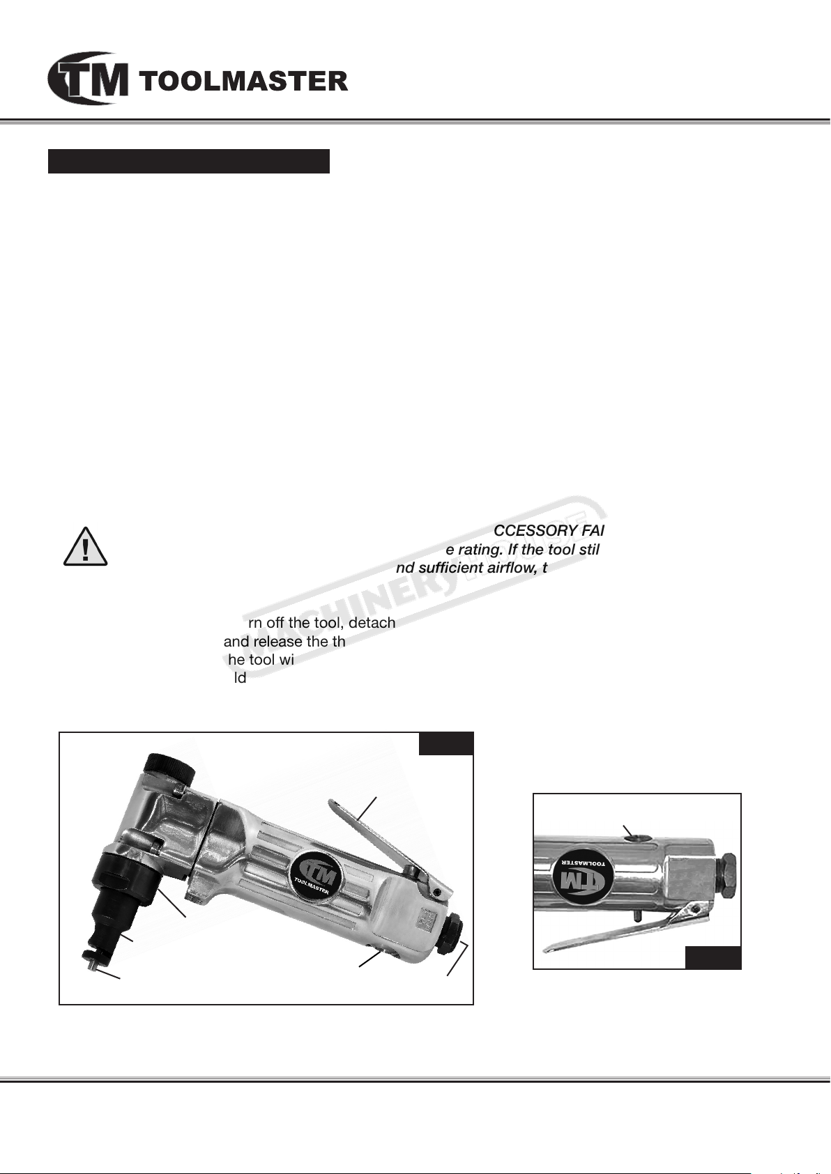
Operating Instructions
1. Disconnect the air tool from the air line.
2. If required, to improve access to the workpiece, the die can be rotated in 90° intervals
through 360°. To do this release the barrel nut then rotate the die to the required angle and tighten
the barrel nut. (See Fig.2)
3. If an automatic oiler is not used, add a few drops of Pneumatic Tool Oil to the airline connection
before use. Add a few drops more after each hour of continual use.
4. Make sure the material to be cut does not exceed the capacity for this Air Nibbler: 1.2mm for sheet
steel, 2mm for aluminum sheeting.
5. Ensure that the workpiece is marked out and secure.
6. Connect the air line to the nibbler.
7. Grip the Air Nibbler rmly, and depress the operating Lever to begin cutting.(See Fig. 2)
8. Apply light pressure to move the Air Nibbler through the material. If the Air Nibbler stalls while
cutting, release pressure on the Operating Lever to turn off the tool, then back the tool out and
restart the cutting process.
9. If the tool requires more force to accomplish the task, verify that the tool receives sufcient,
unobstructed airow (CFM) and increase the pressure (PSI) output of the regulator up to the
maximum air pressure rating of this tool.
CAUTION! TO PREVENT INJURY FROM TOOL OR ACCESSORY FAILURE:
Do not exceed the tool’s maximum air pressure rating. If the tool still does not have
sufficient force at maximum pressure and sufficient airflow, then a larger tool may be
required.
10. To prevent accidents, turn off the tool, detach the air supply, safely discharge any residual air
pressure in the tool, and release the throttle and/or turn the switch to its off position after use. Clean
external surfaces of the tool with clean, dry cloth, and apply a thin coat of tool oil, then store the
tool indoors out of children’s reach.
Fig. 2
operAting trigger
tHrottle VAlVe
Adjustment
bArrel nut
die
punCH
tHrottle VAlVe
Adjustment
Air inlet
Fig. 3
www.machineryhouse.com.au
www.machineryhouse.co.nz
5
Page 6
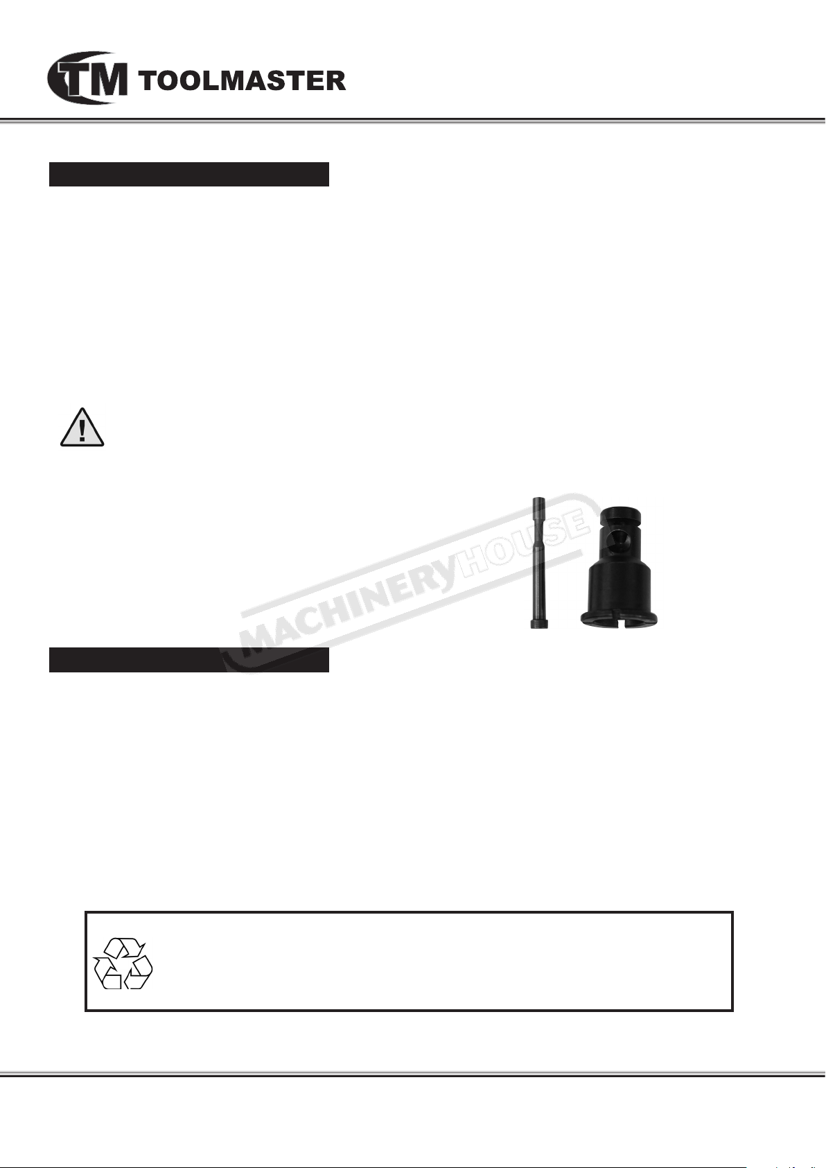
Changing Punch & Die
1. Disconnect the air tool from the air line.
2. Note the orientation of the die revealing the waisted extraction part of the punch. This hole faces the
feed direction of the nibbler.
3. Grip the aluminium alloy air tool head in a soft jaw vice.
4. With a spanner undo the barrel nut.
5. Remove the die, which has four grooves in the mounting ange. These grooves enable four nibbler
positions at 90° intervals.
6. Remove the punch by unscrewing the hexagon headed retainer with a spanner.
7. Inspect the punch and die for wear, replace or renew by reversing by following the removal process.
Apply grease liberally to both punch and die when tting and anticipate the nibbling direction.
WARNING! Disconnect the nibbler from the air supply before changing the punch and die,
servicing or performing maintenance. Replace or repair damaged parts. Use genuine parts
only. Non-authorized parts may be dangerous and will void the warranty.
Replacement Punch and Die
Order Code A082A
Maintenance
1. Daily - Air Supply Maintenance:
Every day, maintain the air supply according to the component manufacturers’ instructions.
Maintain the lubricator’s oil level. Use Pneumatic Tool Oil (Order Code A037)
Drain the moisture lter regularly.
Performing routine air supply maintenance will allow the tool to operate more safely and will also
reduce wear on the tool.
2. Quarterly (every 3 months) – Tool Disassembly, Cleaning, and Inspection:
Have the internal mechanism cleaned, inspected, and lubricated by a qualied technician.
For a full service contact your local Toolmaster service agent.
When not in use, disconnect from air supply, clean nibbler and store in a safe and dry place.
Environmental Protection.
Recycle unwanted materials instead of disposing of them as waste.
All tools, accessories and packaging should be sorted, taken to a recycle centre
and disposed of in a manner which is compatible with the environment.
www.machineryhouse.com.au
www.machineryhouse.co.nz
6
Page 7
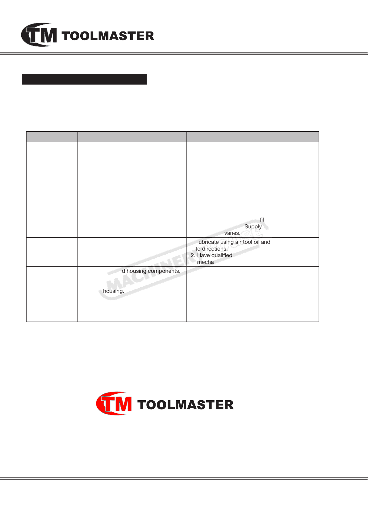
Troubleshooting
Review the troubleshooting and procedures in this section if a problem develops with your Air Tool.
If you are still unable to resolve the problem, then contact your local Toolmaster distributer.
Symptoms Possible Cause Possible Solution
Decreased output.
Housing heats
during use
Severe air leakage
(Slight air leakage
is normal,
especially on older
tools.
1.Notenoughairpressureand/orairow.
2. Obstructed throttle.
3. Incorrect lubrication or not enough
lubrication.
4. Blocked air inlet screen (if equipped).
5. Air leaking from loose housing.
6. Mechanism contaminated.
7. Vane wear or damage.
1. Incorrect lubrication or not enough
lubrication.
2. Worn parts.
1. Cross‑threaded housing components.
2. Loose housing.
3. Damaged valve or housing.
4. Dirty, worn or damaged valve.
1. Check for loose connections and make sure
thatairsupplyisprovidingenoughairow
(CFM) at required pressure (PSI) to the tool’s air
inlet. Do not exceed maximum air pressure.
2. Clean around throttle to ensure free movement.
3. Lubricate using air tool oil and grease according
to directions.
4. Clean air inlet screen of buildup.
5. Make sure housing is properly assembled and
tight.
6.Havequaliedtechniciancleanandlubricate
mechanism.Installin-linelterinairsupplyas
stated in Setup: Air Supply.
7. Replace all vanes.
1. Lubricate using air tool oil and grease according
to directions.
2.Havequaliedtechnicianinspectinternal
mechanism and replace parts as needed.
1. Check for incorrect alignment and uneven gaps.
If cross‑threaded, disassemble and replace
damaged parts before use
2. Tighten housing assembly. If housing cannot
tighten properly, internal parts may be
misaligned
3. Replace damaged components.
4. Clean or replace valve assembly.
INDUSTRIAL AIR TOOLS
www.machineryhouse.com.au
www.machineryhouse.co.nz
7
 Loading...