

Page 1
Industrial Series
ATR-48
AiR POP RIVETER
INSTRUCTION MANUAL
Code: A046
www.machineryhouse.com.au www.machineryhouse.co.nz
Page 2
Important: please read this manual carefully. Note the safety instructions, warnings &
cautions. Use the product correctly and with care for the purpose for which it is intended.
Failure to do so could cause damage or personal injury and may invalidate the warranty.
PLEASE STORE THE MANUAL IN A SAFE PLACE FOR FUTURE USE.
Safety Instructions
rWARNING! Ensure that Health & Safety, and general workshop safety regulations are
adhered to when using this equipment.
ü Familiarize yourself with the applications, limitations and potential hazards peculiar to the
air tool being used.
ü Keep the work area clean and well lighted. Cluttered benches and dark areas increase the
risks of accidents and injury to persons.
ü Keep bystanders, children, and visitors away while operating the tool. Distractions are able
to result in the loss of control of the tool.
ü Keep the air tool clean and regularly maintain the air tool to keep it in good condition
ü Replace or repair damaged parts. Use genuine parts only. Unauthorized parts will validate
the warranty
r WARNING! Always wear approved eye and ear protection when operating the air tool.
ü Maintain correct balance and footing. Ensure the oor is not slippery and wear non-slip
shoes.
ü Remove loose tting clothing. Remove ties, watches, rings and other loose jewelery and
contain, or tie back, long hair.
ü Keep the air tool away from your body and at a safe distance from others.
ü Keep children and unauthorized persons away from the work area.
üSecure unstable workpiece with a clamp, vice or other adequate holding device.
ü Ensure that spent parts are disposed of correctly and do not cause a hazard.
ü When not in use disconnect from the air supply and store in a safe, dry, childproof area.
r WARNING! Disconnect the air tool from the air supply before changing accessories,
servicing or performing any maintenance.
r WARNING! Ensure that the correct air pressure is maintained and not exceeded.
ü Keep air hose away from heat, oil and sharp edges. Check air hose for wear before each use
and ensure that all connections are secure.
û DO NOT use the air tool for any purpose other than that for which it is designed.
û DO NOT operate the air tool if any parts are damaged or missing.
û
DO NOT allow untrained persons to operate the air tool.
û DO NOT operate the air tool when you are tired or under the inuence of alcohol, drugs or
intoxicating medication.
û DO NOT leave the air tool running unattended.
û DO NOT direct air from the air hose at yourself or others.
www.machineryhouse.com.au
www.machineryhouse.co.nz
2
Page 3
Technical Specications
Rivet Capacity (Imperial) 3/32” - 3/16”
Rivet Capacity (Metric) 2.4 - 4.8mm
Traction Power 1220kgs
Air Requirements 4CFM (1131/min)
Maximum Air Pressure 90 PSI
Recommended Air Hose 10mm
Inlet 1/4” BSPT
Sound Pressure 85.5dBA
Length 230mm
Weight 1.5kg
Setup
WARNING: Operating the tool at pressures over the rated capacity may cause severe
damage and/or personal injury. Do not exceed 90 PSI while operating the tool. Do not
use an accessory rated at a lower maximum pressure than the tool.
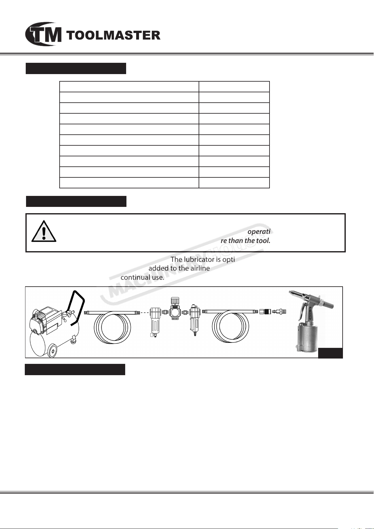
The diagram below is the ideal setup position. The lubricator is optional and If not used, then a few
drops of Pneumatic Tool Oil need to be added to the airline connection before operation. Add a few
more drops after each hour of continual use.
lug
ompressor
C
ose
H
ir
A
F
ilter
egulAtor
r
ubriCAtor
l
ose
H
ir
A
oupler
C
& p
t
ool
Fig. 1
Air Supply
The recommended air system is shown in Fig.1.
1. Ensure that the air pressure is set correctly (90psi).
WARNING! Ensure that the air supply is clean and does not exceed 90psi. Too high an air pressure and/or
unclean air will shorten the life of the air tool due to accelerated wear, and may cause damage and/or
personal injury.
2. Drain the compressor air tank daily. Water in the air line will damage the air tool.
3. Clean the compressor air inlet lter screen weekly.
4. Line pressure should be increased to compensate for unusually long air hoses (over 8 meters). The
minimum hose bore should be 10mm and ttings must have the same inside dimensions.
5. Keep hoses away from heat, oil and sharp edges. Check hoses for wear, and make certain that all
connections are secure.
www.machineryhouse.com.au
www.machineryhouse.co.nz
3
Page 4
Operating instructions
1. Disconnect the air tool from the air line.
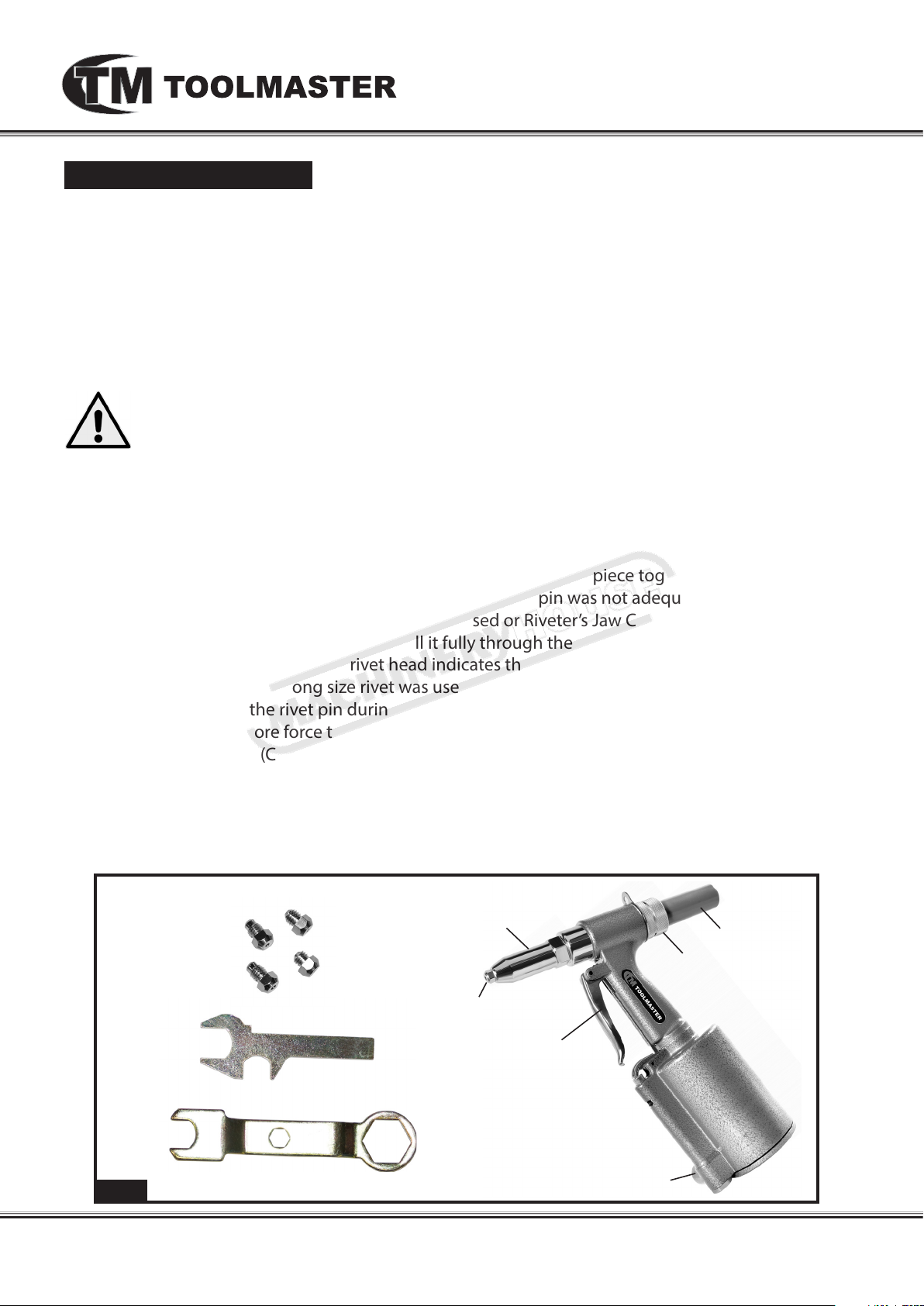
2. Attach the Pin Cap rmly to the Air Riveter by tightening the Pin Cap Nut. When securing turn the
slot in the Pin Cap upwards to avoid spilling any used rivet pins.
3. After selecting the size of the rivet’s pin used, attach the corresponding Nosepiece size (3/16”,
5/32”, 1/8”, or 3/32”) with the spanner.
4. Attach the Air Riveter to the air hose, turn on the air compressor, and set its regulator to
the needed pressure.
CAUTION! TO PREVENT INJURY FROM TOOL OR ACCESSORY FAILURE:
Do not exceed the tool’s maximum air pressure rating. If the tool still does not have sucient
force at maximum pressure and sucient airow, then a larger tool may be required.
5. Insert the small end of a rivet fully into the Nosepiece, making sure to keep clear of the operating
trigger, then insert the rivet through the predrilled hole in the workpiece.
6. Hold the Riveter rmly with both hands, and squeeze the Operating Trigger to activate the Riveter.
Repeat as necessary. Then, release pressure on the Operating Trigger.
7. Check to be sure the rivet looks soild and securely locks the workpiece together.
- If the installed rivet is loose then, this indicates the rivet pin was not adequately pulled through
the workpiece. Either the wrong size rivet was used or Riveter’s Jaw Case is too loose and not
gripping the rivet pin well enough to pull it fully through the workpiece
- A concave, deformed or broken rivet head indicates the rivet pin was pulled too far into the
workpiece. Either the wrong size rivet was used or Riveter’s Jaw Case is too tight and not
properly releasing the rivet pin during installation (See Jaw Cleaning & Replacement)
8. If the tool requires more force to accomplish the task, verify that the tool receives sucient,
unobstructed airow (CFM) and increase the pressure (PSI) output of the regulator up to the
maximum air pressure rating of this tool.
9. When nished, to prevent accidents, detach the air supply, safely discharge any residual air
pressure in the tool, Clean external surfaces of the tool with clean, dry cloth, and apply a thin coat
of tool oil, then store the tool indoors out of children’s reach.
Fig. 2
nose pieCes
spAnners
rivet HeAd
nose pieCe
operAting trigger
www.machineryhouse.com.au
www.machineryhouse.co.nz
pin CAp
pin CAp nut
Air inlet
4
Page 5
Maintenance
It is very important that regular maintenance of the equipment is carried out. The operators meed to
of follow the daily maintenance procedures.
For optimum performance from this machine, the maintenance schedule listed below and in this
section must be followed.
1. BEFORE EACH USE, inspect the general
condition of the tool. Check for:
• loose hardware or housing,
• misalignment or binding of moving parts,
• cracked or broken parts, and
• any other condition that may aect its safe
operation.
2. DAILY - AIR SUPPLY MAINTENANCE:
Every day, maintain the air supply according
to the component manufacturers’ instructions.
Drain the moisture lter regularly.
Performing routine air supply maintenance
will allow the tool to operate more safely
and will also reduce wear on the tool.
3. AFTER EACH USE
When nished operating riveter, disconnect air hose. Wipe o housing with a dry cloth. Place 4 or 5
drops of air tool oil into air inlet; re-connect air and re tool several times to distribute the oil.
Disconnect air.
JAW CLEANING AND REPLACEMENT
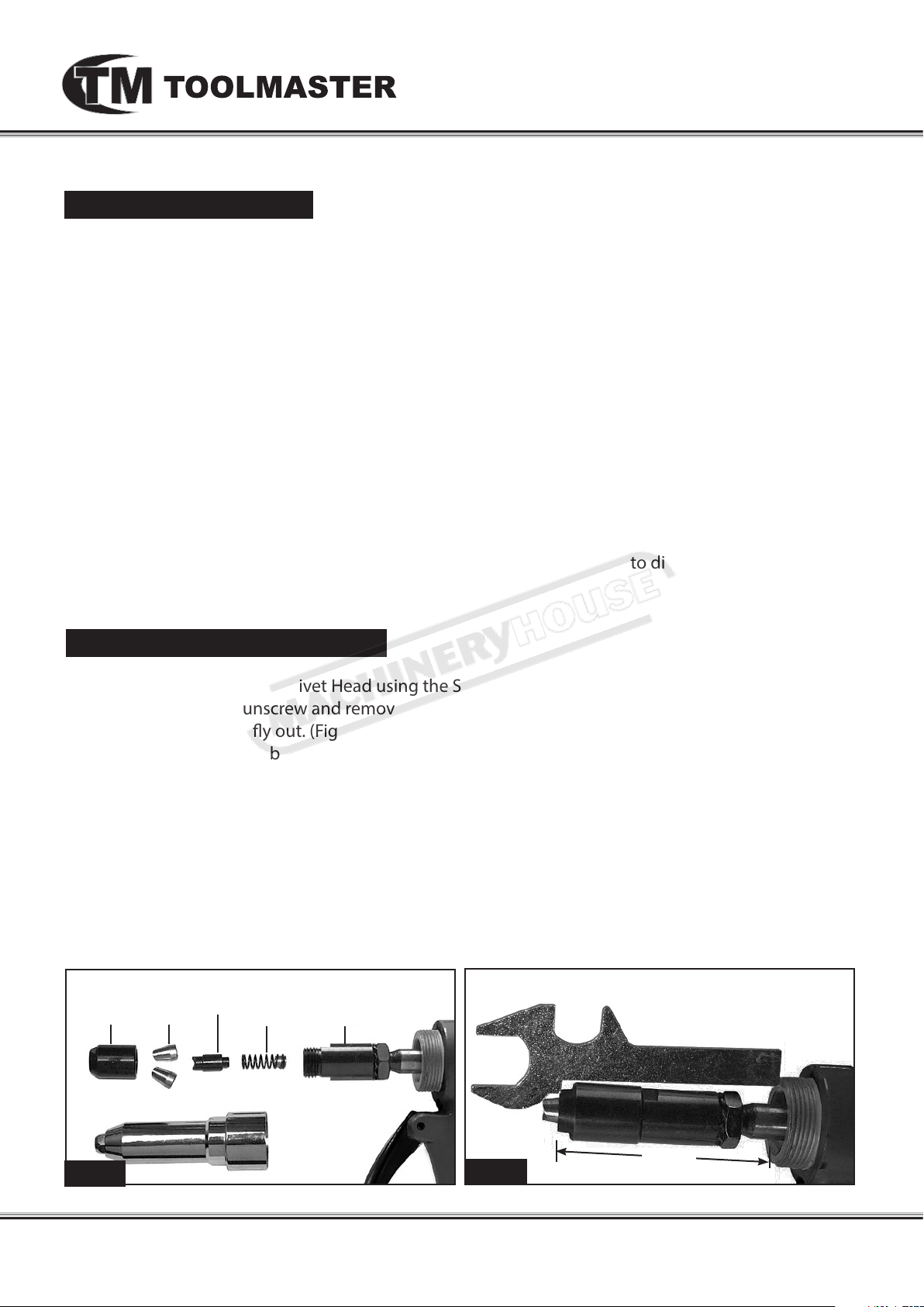
1. Unscrew and remove the Rivet Head using the Spanner.
2. Use the Spanner to unscrew and remove the Jaw Cases. Use care as there is a Spring behind the
Jaw Case which may y out. (Fig. 3)
3. Remove the Jaws from between the Jaw Cases.
4. To clean the Jaws, use a steel brush and mild solvent. Then, apply a light coat of machine oil to
the Jaws and insert them back into the Jaw Case.
5. If any part of the assembly needs replacement, replace the entire assembly at the same time, due
to the possibility of additional parts being damaged when the Jaws were damaged.
6. Use the gauge spanner to check that length of the jaw assembly is correct (Fig. 4). This length
ensures proper spring tension. Rotate the jaw assembly as needed until it ts the span of the
gauge as shown.
7. Reinstall the rivet head.
Front JAw
CAse
Fig. 3
JAw
rivet HeAd
JAw pusHer
spring
bACk JAw
CAse
Fig. 4
www.machineryhouse.com.au
www.machineryhouse.co.nz
71mm
5
Page 6
Troubleshooting
Review the troubleshooting and procedures in this section if a problem develops with your
Air Tool. If you are still unable to resolve the problem, then contact your local Toolmaster service
centre. If additional help with a procedure is required, then contact you distributor.
Note: Make sure you have the model of the machine, serial number,and manufacture date
before calling.
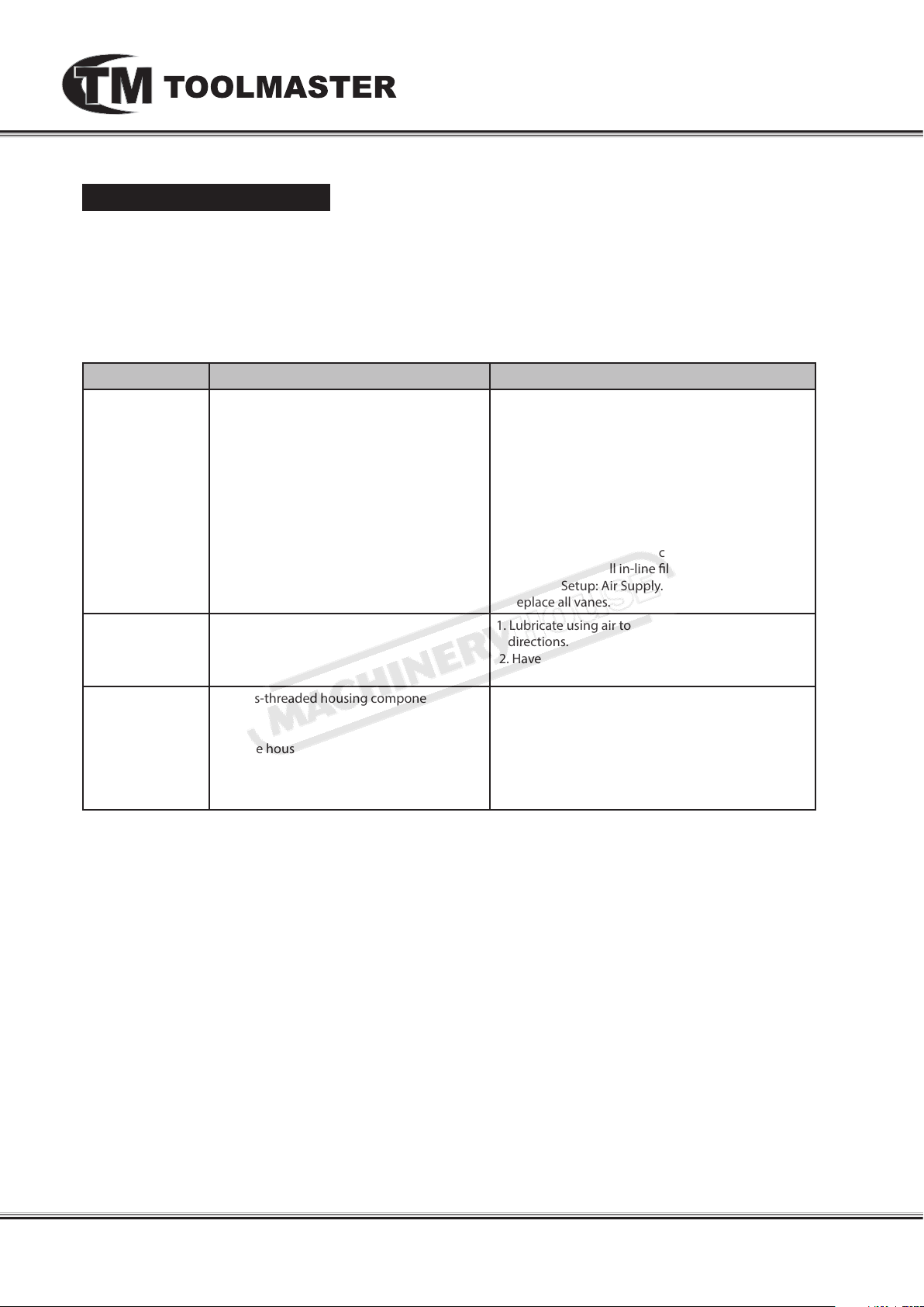
Symptoms Possible Cause Possible Solution
Decreased output.
Housing heats
during use
Severe air leakage.
(Slight air leakage
is normal, especially on older tools.
1. Not enough air pressure and/or air ow.
2. Obstructed throttle.
3. Incorrect lubrication or not enough
lubrication.
4. Blocked air inlet screen (if equipped).
5. Air leaking from loose housing.
6. Mechanism contaminated.
7. Vane wear or damage.
1. Incorrect lubrication or not enough
lubrication.
2. Worn parts.
1. Cross-threaded housing components.
2. Loose housing.
3. Damaged valve or housing.
4. Dirty, worn or damaged valve.
1. Check for loose connections and make sure that air
supply is providing enough air ow (CFM) at
required pressure (PSI) to the tool’s air inlet. Do not
exceed maximum air pressure.
2. Clean around throttle to ensure free movement.
3. Lubricate using air tool oil and grease according to
directions.
4. Clean air inlet screen of buildup.
5. Make sure housing is properly assembled and tight.
6. Have qualied technician clean and lubricate
mechanism. Install in-line lter in air supply as
stated in Setup: Air Supply.
7. Replace all vanes.
1. Lubricate using air tool oil and grease according to
directions.
2. Have qualied technician inspect internal
mechanism and replace parts as needed.
1. Check for incorrect alignment and uneven gaps. If
cross-threaded, disassemble and replace damaged
parts before use
2. Tighten housing assembly. If housing cannot
tighten properly, internal parts may be misaligned.
3. Replace damaged components.
4. Clean or replace valve assembly.
www.machineryhouse.com.au
www.machineryhouse.co.nz
6
 Loading...