

Tool Connection Laser 5258 User Manual
ALWAYS
• Keep tool clean and dust free.
• Keep force screw thread clean and well lubricated (light machine oil).
• Wear eye protection when using.
B
A
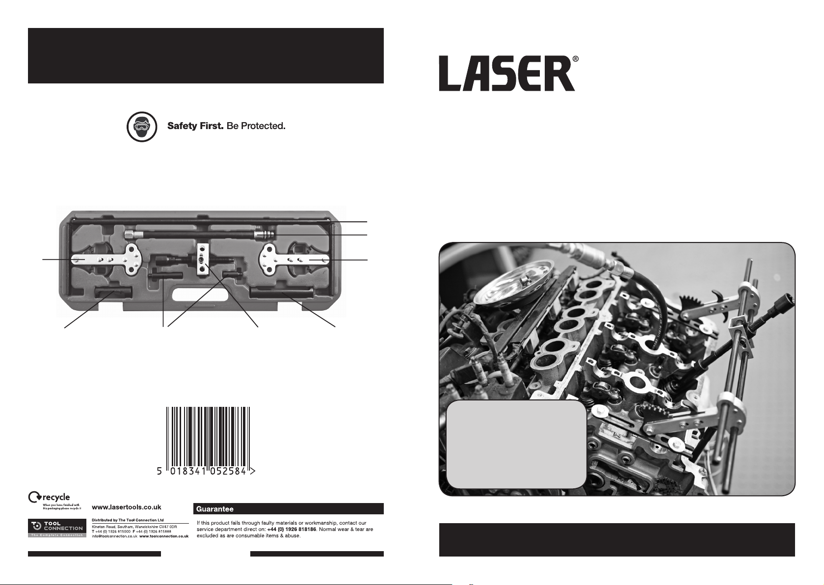
5258
Valve Spring Compressor
For universal use on SOHC and DOHC engines
Designed to allow the removal of valve springs and valve stem oil seals
with the cylinder head in place.
Combustion chamber is pressurised via the supplied spark plug air line adaptor
which holds the valve in place during the valve spring compression operation.
• Fast set up time due to the twin rail pivot system.
• Single handed operation.
C
C
C
E
F
D
E
Contents:
A: Support bar x 2
B: Spark plug Air-line adaptor
C: Adjustable upright x 2
D: Compressor force screw assembly
E: Valve adaptor
F: Extension rods
www.lasertools.co.uk
www.lasertools.co.uk
Instructions
Instructions
Please refer to diagram on back cover
1. Remove camshaft. Sometimes both camshafts need to be removed to access
suitable mounting points for adjustable uprights (see 2).
2. Decide the most suitable mounting points for the two adjustable uprights (C) —
this may be the cam cover fixings, or the camshaft bearing cap mounting points,
for example. Secure one of the two adjustable uprights (C) to the cylinder head
using suitable fixings and washers (do not fully tighten fixings at this stage).
3. Locate the two support bars (A) through the adjustable upright.
4. Slide the compressor force screw assembly (D) along the two support bars until it
is above the valve spring to be removed.
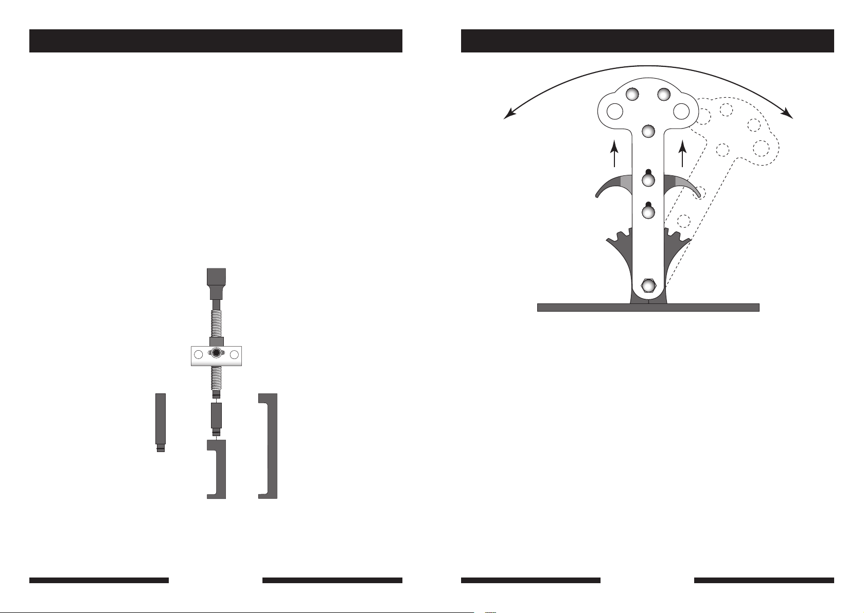
PULL UP ON
FINGER GRIPS
TO ADJUST
ANGLE
5. Attach the second adjustable upright to the support bars and secure (do not fully
tighten fixings at this stage).
6. Choose either the short or long valve adaptor (E) and (if required) the extension
rods (F) (press-fit onto force screw) to enable the correct reach to the valve spring
retaining cap. (Refer to illustration.)
FORCE SCREW
ASSEMBLY
8. Screw force screw clockwise to take up any play against the top of the valve
spring retaining cap.
9. Once everything is lined up correctly tighten adjustable upright mounting bolts.
10. Remove the spark plugs from the engine.
11. Screw the spark plug air line adaptor (B) into the spark plug hole of the cylinder
concerned. Do not overtighten.
12. Connect the adaptor to an air supply (minimum 90psi). This will hold the valve
closed.
13. Tighten force screw using a 1/2”D ratchet or T-bar. The valve spring is then
compressed and the retaining collets can be removed.
EXTENSION
60mm
125mm
RODS
30mm
14. Release force screw by unscrewing; it can then be slid along the support bars to
VALVE
ADAPTORS
70mm
7. Ensure that the force screw is in the same axis as the valve by adjusting the
uprights and the force screw itself. The upright mounting position is adjusted by
gain access to the valve spring.
15. The valve spring can then be removed (and replaced if necessary) and new valve
stem seals can be fitted.
16. Re-compress the valve spring, insert the retaining collets and release tension on
force screw to finish.
17. Repeat instructions for other valves as necessary.
sliding the base plates on the fixings. The angle of the uprights is adjusted by
pulling up on the finger grips and moving the spring compressor assembly to
align. Release finger grips to lock position. (Refer to illustration.)
www.lasertools.co.uk
2 3
NOTE: Instructions are for guidance only.
Please refer to the manufacturer’s service manual.
www.lasertools.co.uk
 Loading...