

TONO THETA-7000E Instruction Manual

TONO
COMMUNICATIONS COMPUTER
Θ - 7000E
INSTRUCTION MANUAL
TONO CORPORATION
230 MOTOSOJA-MACHI, MAEBASHI-SHI, 371. JAPAN

TABLE OF CONTENTS
1. Features & Precautions ....................................................... 1
2. Location and Function of controls ......................................... 4
i) Front panel (Keyboard)
ii) Back panel
3. Accessories supplied ........................................................... 7
4. Connection ......................................................................... 7
4-1. Basic System ........................................................ 7
i) Power Supply
ii) TV set
iii) Transceiver
4-2. Expanded System ................................................. 10
i) Oscilloscope
ii) Printer
5. Operation
i) Preliminary Setting ......................................... 11
ii) Procedure to Power Up Equipment .................. 11
iii) Speed and Weight Setting ............................. 12
iv) Tuning ......................................................... 13
v) Transmission ................................................. 16
1. Buffer Memory
2. Correction of Miswritten Characters
3. Automatic Key Repeat
vi) Functions ..................................................... 17
1. Channel Memory
2. SEND Function
3. Split Screen
4. Stop of Transmission
5. "Stand-by" Procedure
6. CW Identification
7. Other Function Keys
8. Indications
vii) Using a Tape Recorder for Storage ................ 22
6. Application of a Microcomputer as an Intelligent Terminal ...... 23
7. How to Set Cells for the Battery Backed-up Memory .............. 23
Key function and display ......................................................... 24
Special Character ASCII 00–1F ................................................ 27
Specifications ......................................................................... 28
Input/ Output Circuit .............................................................. 29

- 1 -
1. FEATURES & PRECAUTIONS
Features:
1. Communications Computer Θ-7000E
Due to the most up-to-date computer technology, one piece of equipment can now handle
both transmitting and receiving in CW, RTTY and ASCII.
2. VHF and Composite video output provided:
Both a home TV set and video monitor outputs are provided for display purposes.
3. Printer interface
Centronics para. Compatible interface enables easy connection of a low-cost dot printer for
hard copies.
4. Wide range of transmitting and receiving speeds
10 communication speeds for transmitting (with automatic CW speed adjustment of receive) and 9 communication speeds for transmitting and receiving in RTTY and ASCII. The
multiple speed feature makes the Θ-7000E ideal for Amateur, business and commercial use.
5. Built-in demodulator for high performance
Three-step shift (either 170 Hz, 425 Hz, 850 Hz) can be obtained using either High Tone or
Low Tones. Manual adjustment is available by FINE TUNING control.
6. Crystal controlled modulator
A transceiver without FSK function can transmit in RTTY mode by utilizing the high stability
crystal-controlled modulator controlled by the computer.
7. Convenient ASCII key arrangement
The keyboard layout is the same as a regular typewriter and automatic insertion of LTR/FIG
code makes operation a breeze.
8. Large capacity display memory
The two-page display memory contains 32 characters × 16 lines per page. Page selection
is operated via the keyboard.
9. Split-screen
With a keyboard command, the first page can be divided in two; the upper half for transmit
and the lower half for receive. Sentences can be edited whilst receiving.
10. Automatic Transmit/Receive switch
The transmit/receive switch is controlled by the microprocessor. (Manual operation is also
available.) Built-in remote control key function controls the transmit/receive switch of the
transceiver.
11. Anti-noise
A new anti-noise circuit prevents garbled messages when there is no signal.
12. Battery backed-up memory
Data in the battery backed-up memory is retained when the external power source is removed. The Θ-7000E has provision for 64 characters × 7 channels in the non-volatile
memory. Data from a memory can be repeated 1–9 times from a keyboard instruction.
Every channel can read out continuously. The channel number in use is displayed in the
buffer.
13. SEND function
The SEND function sends data displayed on the screen, including any channel data after instruction from the keyboard. The message can be stopped and restarted.
14. Buffer memory
A 53-character-buffer-memory is displayed on the 17th and 18th lines on the screen. The
characters move to the left erasing one by one as soon as they are transmitted. Data in the
channels can be displayed in the buffer.
15. Rub out function
Mistakes can be erased whilst the information is still in the buffer memory. If the mistake
has already been sent a correcting code will be transmitted.
16. Simultaneous access of the memory
Whilst receiving, it is possible to write into the channel memory and the buffer memory
from the keyboard. When sending from the channel memory or the screen it is possible to

- 2 -
write into the buffer memory.
17. Pre-loading function
The buffer memory can momentarily store data and release it on an instruction from the
keyboard.
18. Channel No., Page No., and Case No.
Channel No., Page No., and Case (LTR/FIG) in RTTY are displayed in the 17th line of the
screen.
19. CR (Carriage return)/LF (line feed) cancel function
When receiving CR or LF, they are replaced by = (equal) and _ (underline) respectively for
effective use of the screen.
20. Cursor control function
Full cursor control (up/down-left/right) is available from the keyboard.
21. WORD MODE operation
Characters can be transmitted by word groupings.
22. Automatic CR/LF
While sending, CR/LF are automatically inserted once every 72 (64 or 80) characters.
23. Automatic LETTER code insertion
With LETTER switch ON, LETTER code can be transmitted continuously while transmitting
from the keyboard is stopped.
24. ECHO-BACK function
With a keyboard instruction, received data can be read and sent out at the time. A cassette
tape can be used as the source data.
25. WORD-WRAP-AROUND function
In receive mode word-wrap-around prevents the last word of the line from splitting in two.
This function is released with a keyboard instruction.
26. Transmit/receive in ASCII mode in RTTY
On instruction from the keyboard, the same AFSK signals as used in RTTY are transmitted
in ASCII mode.
27. CW Identification function
Keyboard controlled CW identification is available if required.
28. MARK-AND-BREAK (SPACE-AND-BREAK) system
Either mark or space tone can be used to copy RTTY.
29. Monitor circuit
A built-in-monitor circuit with an automatic transmit/receive switch enables checking of the
transmitting and receiving state. In receive mode it is possible to check the output of the
mark filter, the space filter and AGC amplifier prior to the filters.
30. CW practice function
The Θ-7000E reads data from the key and displays the characters on the screen.
31. Variable CW weights
For CW transmission, weights (ratio of dot to dash) can be changed within the limits of
1:3–1:6.
32. Cross-pattern checking output terminal
Provision has been made for attachment of an oscilloscope to aid tuning. This supplements
the tuning LED and audio monitor provided in the system.
33. Log-computer output provided
The Θ-7000E has an output terminal for connection to a log-keeping computer.
34. Test message function
"RY" and "QBF" test messages can be repeated with this function.

- 3 -
Precautions:
1. Before operating the set, please read this INSTRUCTION MANUAL thoroughly.
2. Before using with a transceiver practice with a TV set.
3. Adjust SWR between the transceiver and antenna as follows:
OUTPUT SWR
10 W 1.5
10 W – 100 W 1.3
100 W – 500 W 1.1
4. Take care to properly connect in. the connection to the input circuits and output circuits. Input
signal and load should be within the ratings.
5. Voltage of DC power supply should be within the range of DC 11 V – 14 V.
6. Where the Input impedance of the TV set is 300 ohms (not 75 ohms) put a matching trans-
former of 75 ohms : 300 ohms between the Θ-7000E and the TV set.
7. DC power supply for the Θ-7000E should not be connected to other sets.
8. The Θ-7000E should be installed at a well-ventilated dry place not exposed to the direct rays of
the sun with special care for heat radiation.
9. While automatic CR/LF insertion function is working, CR/LF is inserted automatically at space
which is written anywhere but in the last 5 letters of line.
10. Use RTTY modem at 150 Baud less.
- 4 -
2. LOCATION AND FUNCTION OF CONTROLS
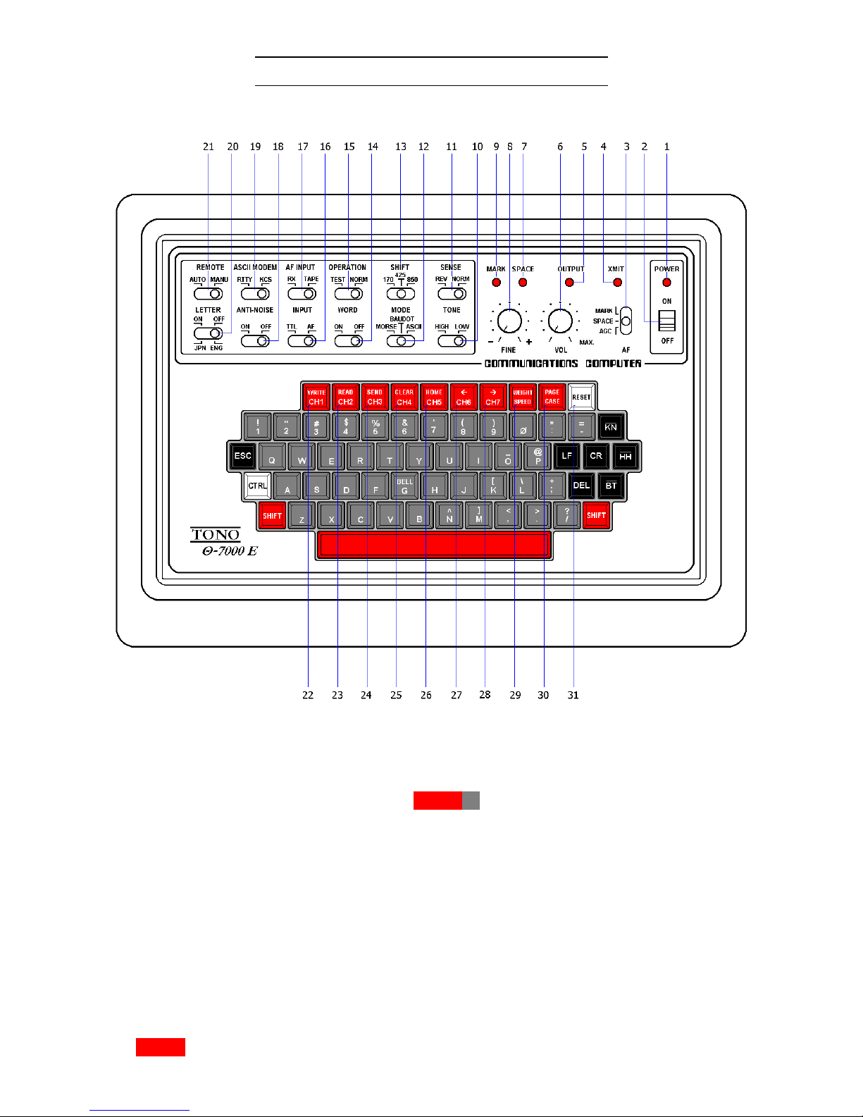
i) Front panel (Keyboard)
1. POWER pilot LED: lights when the POWER switch is turned ON.
2. POWER switch
3. AF switch: [AGC] output from AGC can be monitored
[MARK] or [SPACE] output from respective filters can be monitored.
4. XMIT indicating LED: turns on and of with SHIFT X operated when the REMOTE switch is set
at MANUAL; turns on and off corresponding to key operation while at AUTO.
5. OUTPUT indicating LED: indicates output level. It lights at the time of "mark" and does not
light at the time of "space". V.V.
6. VOL: controls the volume of a monitor speaker.
7. SPACE indicating LED: Indicates space of input signal.
8. FINE tuning control: provides the fine tuning of shift width in receiving in BAUDOT mode and
RTTY of ASCII.
9. MARK indicating LED: Indicates mark of input signal.
10. TONE switch: indicates High Tone or Low Tone in RTTY.
11. SENSE switch: changes the polarity of mark/space in input and output.
12. MODE switch: for mode selection.
13. SHIFT switch: sets shift width in RTTY
14. WORD switch: transmits characters in the buffer memory by word groupings by pushing
SPACE (or LF or CR ).

- 5 -
15. OPERATION switch: controls the state of the keying circuit.
16. INPUT switch: [TTL] obtains input from TTL LEVEL IN jack.
[AF] obtains input from others.
17. AF INPUT switch: relates to AF INPUT jacks on the back panel.
18. ANTI-NOISE switch: Helps to prevent garble when there is no signal.
19. ASCII MODEM switch: relates to AF INPUT KCS and RX/TAPE on the back panel.
20. LETTER switch: LETTER code is transmitted when transmitting in RTTY.
21. REMOTE switch: puts the transceiver in transmitting state by pushing any key (AUTO) or
SHIFT X (MANUAL).
22. WRITE | CH1 key ┐
23. READ | CH2 key │
24. SEND | CH3 key │
25. CLEAR | CH4 key │ Refer to page 22
26. HOME | CH5 key │
27. | CH6 key │
28. | CH7 key │
29. WEIGHT | SPEED key ┘
30. PAGE | CASE key
31. [ RESET ] key: put the set in the initial state.

- 6 -
ii) Back panel
1. PHONE jack: Connect with an earphone
2. FUSE: 2 A
3. VIDEO RF jack: Connect with a home TV set.
4. VIDEO COMPOSITE jack: Connect with a video monitor.
5. POWER supply jack: DC 12 V in
6. OSCILLO SPACE jack: Oscilloscope should be connected to this jack for the space output for
cross pattern.
7. OSCILLO MARK jack: Oscilloscope should be connected to this jack for the mark output for
cross pattern.
8. FSK ID jack: Connect 100 kΩ – 200 kΩ resistor for CW identification.
9. FSK KEY jack: Connect with RTTY keying terminal of the transceiver for FSK function in RTTY.
10. CW KEY POSI jack: Connect to the transceiver for CW (refer to page 8)
11. CW KEY NEGA jack:
12. REMOTE jack: Connect to PTT terminal of the transceiver for remote control.
13. AFSK OUT TAPE jack: Connect to MIC terminal of the cassette tape recorder.
14. GAIN control: Controls the AFSK output level.
15. AFSK OUT TX jack: Connect to MIC terminal of the transceiver.
16. AF INPUT TAPE jack: Connect to EARPHONE terminal of the tape recorder.
17. AF INPUT RX jack: Connect to EXT SP terminal or line output of the transceiver.
18. AF INPUT KCS jack: Connect to EARPHONE terminal of the tape recorder.
19. TTL LEVEL OUT jack: For output in TTL level without modulation.
20. TTL LEVEL IN jack: For non-modulated signals in CW, BAUDOT or ASCII and when using with a
hand key.
21. PRINTER CABLE OUTLET
- 7 -
3. ACCESSORIES SUPPLIED
Instruction manual 1
Pin plug 16
Headphone plug 1
Power source cord 1
Coaxial cable 4 m
Connector for printer 1
4. CONNECTION
4-1 Basic System
i) Power supply
Before connecting a power lead to your DC power supply, the setting of the voltage must
be within the range of DC 11 V – 14 V.
After confirming that the DC source switch and POWER switch of the Θ-7000E indicates
OFF, connect a plus (+) of POWER supply jack of the Θ-7000E with the plus (+) terminal of
DC source; minus (–) with minus (–) terminal.
ii) TV set
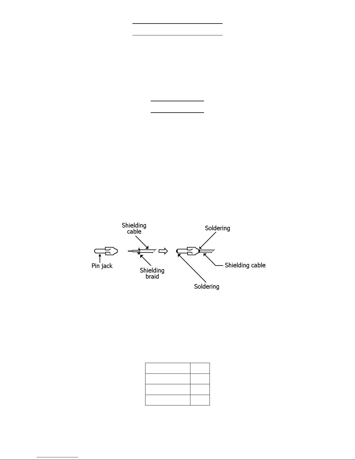
1. Solder an ancillary coaxial cable and a pin plug as shown in Fig. 3. After having soldered,
connect the pin plug to the RF pin jack of the Θ-7000E and the other end of the coaxial cable to an antenna terminal of a home TV set. Tune TV set to CH3 or CH4,
Fig. 3
or 2. Connect the pin plug to COMPOSITE pin jack for a display monitor.
We recommend you TONO display monitor model: CRT-12,, which is specially designed for
Amateur radio communications and has very stable display without being interfered by a
electric wave.
iii) Transceiver
Make sure SWR is as follows; to enable correct operation.
OUTPUT SWR
10 W 1.5
10 W – 100 W 1.3
100 W – 500 W 1.1
Table 1

- 8 -
Fig. 4
NOTE: 1) Check the polarity against the ground by the tester and connect with the respective
jack.
2) No need to connect when using with AFSK function of Θ-7000E.
3) Only for CW identification with FSK function of the transceiver.
4) No need to connect when using with FSK function of the transceiver.
5) For Home TV set "RF"; for Monitor set "COMPOSITE".
 Loading...