

TONO Theta 7000 Instruction Manual

TONO
COMMUNICATIONS COMPUTER
Θ - 7000
INSTRUCTION MANUAL
TONO CORPORATION
230 MOTOSOJA-MACHI, MAEBASHI-SHI, 371. JAPAN
TEL 0272-52-6284

**************************** CONTENTS ***************************
Page
1. Features ...................................................................................................... 1
2. How to use ................................................................................................. 5
3. Designation and Explanation of Parts ............................................................ 7
4. How to operate ........................................................................................... 10
4.1 Initialization ................................................................................................ 10
4.2 Preliminary setting ....................................................................................... 11
4.3 Procedure for power ON ............................................................................... 11
4.4 Tuning of a wireless set for transmission ........................................................ 12
4.5 Speed setting for transmitting and receiving .................................................. 12
4.6 Weight setting in CW mode ..........................................................................
4.7 Tuning for receiving .....................................................................................
4.8 Recording of signals during receiving ............................................................ 14
4.9 Transmission ............................................................................................... 15
4.10 How to use battery backed-up memory ......................................................... 19
4.11 How to use SEND function ........................................................................... 19
4.12 Stop of transmission .................................................................................... 20
4.13 "Stand-By" procedure .................................................................................. 20
4.14 How to use function key ............................................................................... 20
4.15 How to use a tape recorder .......................................................................... 21
4.16 CW practice ................................................................................................ 21
4.17 Application of a microcomputer as an intelligent terminal ................................ 22
4.18 Operation example ...................................................................................... 22
RATINGS ............................................................................................................... 23
INPUT/OUTPUT CIRCUIT ........................................................................................ 24

- 1 -
1. FEATURES
(1) COMMUNICATION COMPUTER
The Θ-7000 is made with the newest technique of computer; transmits and receives the CW
(Morse Code), RTTY (Baudot code) and ASCII (American Standard Code for Information Interchange)
and projects them to a home TV set. It may be used as an intelligent terminal for a microcomputer as
well as for a wireless set.
(2) WIDE RANGE OF TRANSMITTING AND RECEIVING
Its transmitting-receiving speeds are 10 steps for transmitting the CW, automatic-following for receiving the CW, 4 steps for transmitting-receiving the RTTY and 2 steps for transmitting-Receiving the
ASCII. It may be effectively used not only for the radio amateur communications but also for the
business communications.
(3) HIGH PERFORMANCE DEMODULATOR
It has an active filter type demodulator of high stability and reliability in it, which results in a very
high communication performance. For the RTTY, three steps (shift with 170 Hz, 425 Hz and 850 Hz)
and 'FINE TUNING' are available, so the demodulator may be very easily operated.
(4) CRYSTAL-CONTROLLED MODULATOR
It has a high precision, high stability crystal-controlled modulator which is controlled by the computer attached to it and the RTTY may be transmitted and received even with a machine without FSK
function.
(5) EASILY OPERATEABLE KEYBOARD ARRANGEMENT
It has a keyboard arrangement about the same as the ordinary typewriter; even for RTTY it is not
necessary to change LTR and FIG manually and the code of LTR and FIG may be added automatically.
(6) LARGE CAPACITY DISPLAY MEMORY
It has the capacity for two pages of 32 characters × 16 lines and the pages may be changed
easily by operating the key switch, so such a use that one page is for receiving and the other page is
for transmitting may be available. When the screen is filled up, the lines go up automatically with the
scrolling function.
(7) AUTOMATIC CHANGE FROM/TO TRANSMITTING TO/FROM RECEIVING
Change of transmitting and receiving is controlled automatically by the computer.
(8) A BATTERY BACKED-UP MEMORY
It has a battery backed-up memory for 32 characters × 7 channels; the sentences do not volatilize when the power source is cut off. The computer will let the machine work automatically at any
time with your key switch operation if you put your call sign or sentences which you often use it.
(9) OUTPUT REPEATING
The sentence memorized in the battery backed-up memory may be put out repeatedly with the
key switch operation. It may be used very conveniently at calling.

- 2 -
(10) 'SEND-OUT' FUNCTION
The sentence on the screen sent from the keyboard or received from the outside may be sent out
with the key operation of one time from the first character to the character before the cursor. A sentence of up to 511 characters may be sent out at one time.
(11) USE OF A CASSETTE TAPE-RECORDER AS A SUPPLEMENTARY MEMORY
The sentence may be put in the cassette tape-recorder or the sentence may be led in and displayed on the screen from the cassette tape-recorder. This function may be very effectively utilized
being connected with the 'SEND-OUT' function, so paper tapes are no more necessary for the RTTY.
(12) BUFFER MEMORY FOR DISPLAYING ON THE TV
The information in the buffer memory which has the capacity of 23 characters may be put on the
lowest line (17th line) on the screen and they move to the left every time one of them is sent out, so
the going -out sentence may be well observed.
(13) 'RUB-OUT' FUNCTION
When a wrong character is sent to the buffer memory from the keyboard, the character may be
canceled before it is sent out of the buffer memory and a correcting code may be put out after it is
sent out.
(14) SIMULTANEOUS ACCESS
During receiving the communication, the sentence may be put in the buffer memory or the battery backed-up memory. Efficient QSO may be made because the sentence may put in the buffer
memory even when the battery backed-up memory is transmitting or the displaying memory is transmitting with the 'SEND-OUT' function.
(15) PRELOADING FUNCTION
Buffer memory may memorize the sentence sent from the keyboard and by using this function at
the time of receiving, transmitting may be made just after receiving and beautiful continuous may be
sent out.
(16) ONLY THE RECEIVED SENTENCES MAY BE DISPLAYED IF NECESSARY
When you don't need the display of the sent out sentence, only the received sentence may be displayed though both of them are available.
(17) DISPLAYING CHANNEL NO., PAGE NO. AND THE CASE
The channel number of the battery backed-up memory, the page number of the screen, the case
(LTR or FIG) in the RTTY may be displayed on the lowest (17th) line.
(18) FUNCTION OF CANCELING CR AND LF
When CR (carriage return) or LF (line feed) is received or at writing with the keyboard, CR and LF
are replaced with = (equal) and _ (underline) on the screen respectively and the screen may be used
effectively.
(19) FUNCTION OF CONTROLLING CURSOR MOVEMENT
Cursor movement may controlled by the keyboard. In the case of the ASCII mode, the cursor
movement may be controlled by the external signals and it is effective when the machine is con-

- 3 -
nected to a microcomputer.
(20) SINGLE-SIDED RTTY MAY BE RECEIVED
So-called single-sided RTTY of intermission of either marks or spaces may be clearly received.
(21) 'UNSHIFT ON SPACE' FUNCTION
When you receive a space (space of Baudot code) in the case of the RTTY, the CASE changes to
LTR regardless of the case so far. It may be effective to be used for receiving signals very close to the
noise level.
(22) A MONITOR CIRCUIT
A monitor circuit which automatically changes transmitting and receiving to each other is attached; the situation of transmitting and receiving may be found through the speaker. At the time of
receiving, the output from the mark filter, the output from the space filter and the output from the
AGC amplifier in the front stage of the filter may be monitored.
(23) CW PRACTICE FUNCTION
If you connect the key to this machine and operate the key, the machine will read it and display it
on the screen. In this case, the CW key operation's output circuit works according to the operation of
the key.
At the time of receiving CW, always different sentences may be received by using the output repeating function (9) and the 'SEND-OUT' function (10), which makes your practice effective and interesting.
(24) CW WEIGHT IS CHANGEABLE
At transmitting the CW, the length of the dash may be changed in the range of 1:3 ~ 1:6.
(25) OUTPUT TERMINALS FOR OBSERVING THE CROSS PATTERN
The demodulator of this machine may be easily tuned with the tuning indicating LED or the monitor circuit. Output terminals for observing the cross pattern with an oscilloscope are attached.
(26) OUTPUT PORTS FOR A PRINTER
8 bit parallel I/O port is attached for connecting to a printer. In this case, the output is ASCII and
a strobe pulse comes out every time of putting out a character.
(27) DC TWO WAY POWER SOURCE SYSTEM
Both power supplies +12 VDC and +5 VDC may be used.
(28) FUNCTIONAL DESIGN
The keys, switches and others are arranged functionally to be used easily and everything as well
as the case is designed functional and elegant.
(29) CARETAKING COMMUNICATION IS AVAILABLE
Messages may be received while you are out by attaching the option part Θ-22 and making a network with your group members and in this case, no messages may be received from outside the network. Also the RTTY's function may be expanded by the Θ-22.
- 4 -
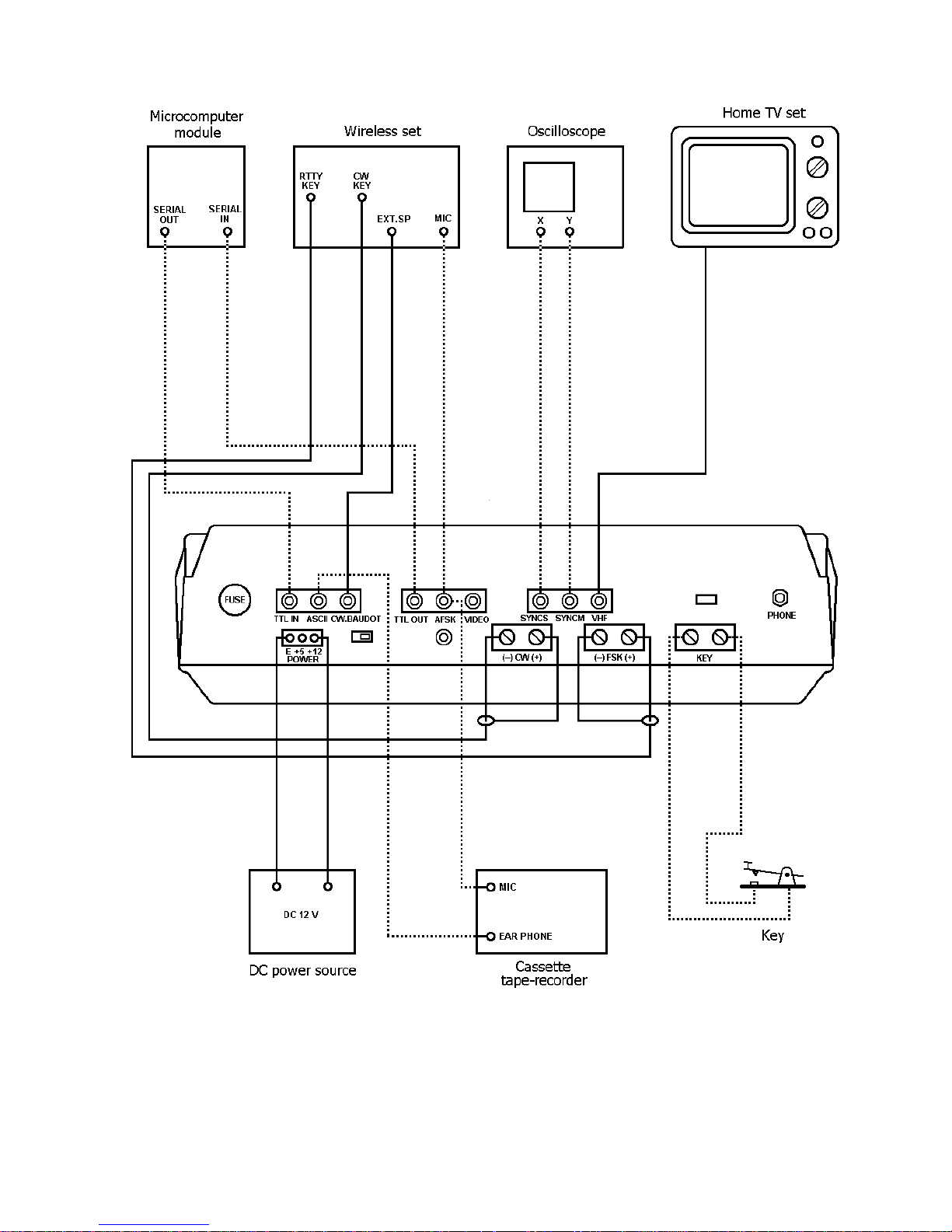
Figure 1: Connection
- 5 -
2. HOW TO USE
2.1 Accessories for the Θ-7000
Instruction manual 1
Pin plug 9
Earphone plug 1
Power source cord 1
Coaxial cable 4 m
2.2 Installation
The Θ-7000 should be installed at a well-ventilated dry place not exposed to the direct rays of the
sun with special care for heat radiation.
2.3 Connection
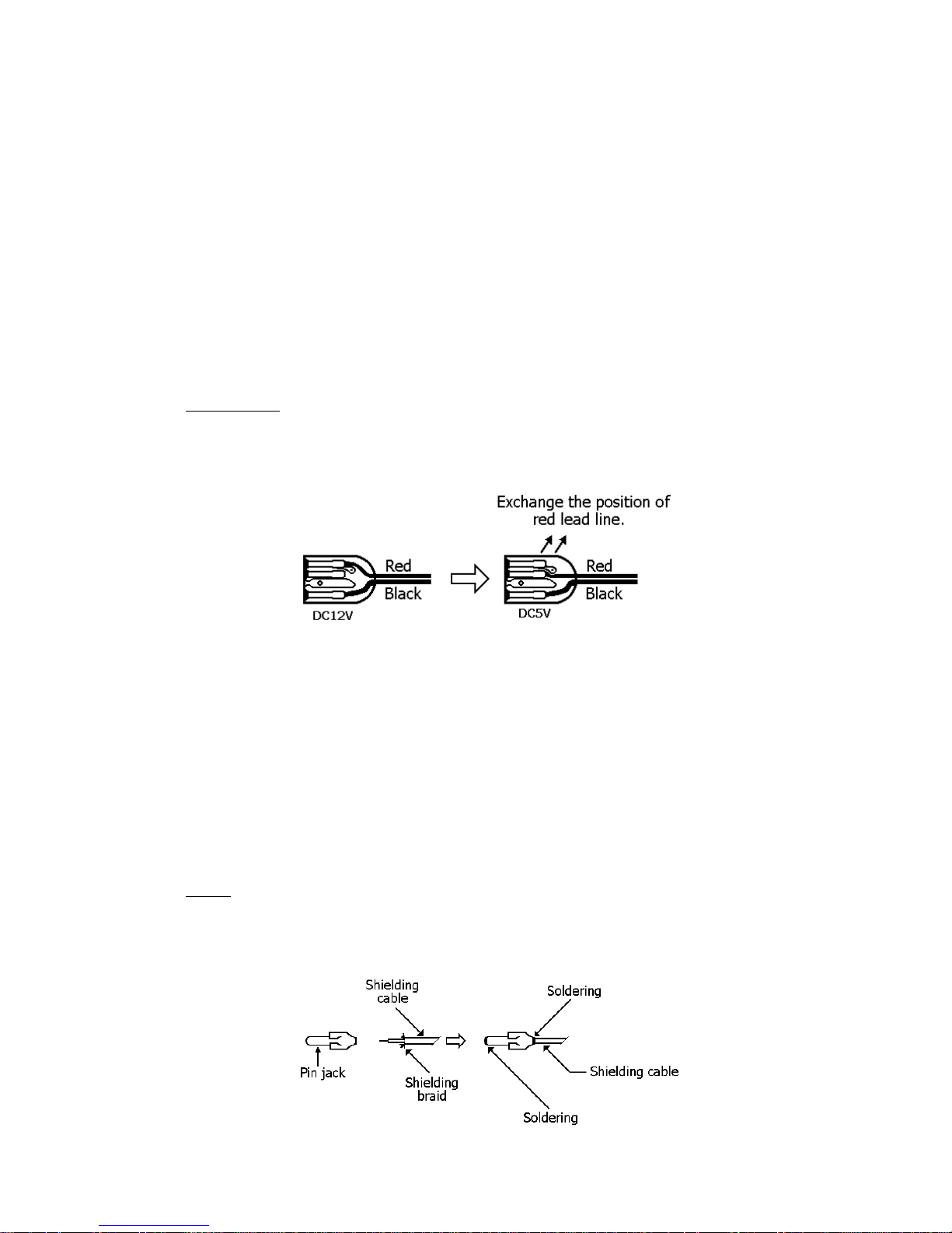
(1) Power supply
An ancillary source power supply cord is connected for 12 VDC. In the case of using 5 VDC,
change the connection within source cord connector as shown in Fig. 2.
Figure 2
Before connecting a source cord to your DC power supply, the setting of source voltage is necessary as follows:
In the case of 12 VDC 11 V ~ 13,8 V
In the case of 5 VDC 4.75 V ~ 5.25 V
Source voltage should be stabilized without ripple in the case of 5 VDC. After confirming a DC
source switch and a power switch of the computer indicate OFF, connect the red source cord of the
computer to a plus (+) terminal of DC source, a black source cord to a minus (–) terminal.
(2) TV set
Solder an ancillary coaxial cable and a pin plug as shown in Fig. 3. After having soldered, connect
the pin plug to a VHF pin jack of the Θ-7000 and the other end of the coaxial cable to an antenna terminal of a home TV set.
Figure 3

- 6 -
(3) Wireless set
Before connecting, adjust SWR as follows:
In the case of output less then 10 W: less than 1.5
In the case of output from 10 W to 100 W: less than 1.3
In the case of output from 100 W to 500 W: less than 1.1
(i) Speaker
Solder the ancillary coaxial cable and a pin plug as shown in Fig. 3. After soldering,
connect the pin plug to the CW/BAUDOT pin jack of the Θ-7000 and the other end to an external
speaker terminal or an earphone terminal of a wireless set.
(ii) In CW mode
Connect the cable to a key jack for CW of a wireless set, check the polarity by a tester
and connect its plus (+) to the plus (+) of a screw terminal for CW of the computer; its minus (–) to
the minus (–) of the computer. Take care not to exceed the rated capacity of keying circuit of 1.5 A,
150 V.
(iii) In RTTY mode
° In the case of a wireless set with FSK function:
Connect the cable to a KEY jack for RTTY of the wireless set, check the polarity by a
tester and connect its plus (+) to the plus (+) screw terminal for FSK of the computer, its minus (–)
to the minus (–) terminal. Special care should be exercised not to exceed the rating: 1.5 A for the
maximum keying circuit current and 150 V for the maximum voltage.
° In the case of a wireless set without FSK function:
Solder the ancillary coaxial cable and a pin plug as shown in Fig. 3. After soldering,
connect the pin plug to a pin jack for AFSK of the Θ-7000 and the other end to a microphone terminal
of the wireless set. The shielding braids of the cable should be connected to GND side of the microphone terminal.
(4) Key
For manipulation practice in CW mode, connect keys to a screw terminal for KEY of the com-
puter.
(5) Oscilloscope
Cross pattern can be observed with oscilloscope by the following procedures: solder the coaxial cable or shield cable with two pin plugs respectively as shown in Fig. 3; after soldering, connect
the pin plugs to pin jacks, SYNCM and SYNCS; connect the cable in SYNCM to the V-axis input to the
oscilloscope and the cable in SYNCS to the H-axis input.
 Loading...