

Page 1

TONO
COMMUNICATIONS COMPUTER
Θ - 550
INSTRUCTION MANUAL
TONO CORPORATION
98 MOTOSOJA-MACHI, MAEBASHI-SHI, 371. JAPAN
Page 2

1. FEATURES & PRECAUTIONS
1-1. Features ........................................................................................... 1
1-2. Precautions ...................................................................................... 3
2. LOCATIONS
2-1. Locations .......................................................................................... 4
3. CONNECTIONS
3-1. Basic System .................................................................................... 5
3-2. Expand System ................................................................................. 6
3-3. Connections ...................................................................................... 7
4. PRELIMINARY SETTING
4-1. MORSE (CW) Mode ........................................................................... 8
4-2. BAUDOT (RTTY) Mode ....................................................................... 9
4-3. ASCII (RTTY) Mode ........................................................................... 11
4-4. MORSE Code Random Generator ........................................................ 12
4-5. How to Modify the Preliminary Setting ................................................ 12
5. OPERATION
5-1. MORSE (CW) Mode ........................................................................... 13
5-2. BAUDOT (RTTY) Mode ....................................................................... 15
5-3. ASCII (RTTY) Mode ........................................................................... 16
TABLE OF CONTENTS
6. SPECIAL FUNCTIONS
6-1. Anti-Noise Circuit .............................................................................. 17
6-2. Unshift-On-Space Function ................................................................ 17
6-3. Echo-Back Function ........................................................................... 17
6-4. Morse Code Random Generator .......................................................... 17
6-5. Morse Practice .................................................................................. 18
6-6. Recording of Received Signals ............................................................ 18
6-7. Automatic CR/LF after Receiving ........................................................ 18
6-8. Word-Wrap-Around ........................................................................... 18
6-9. Send Function ................................................................................... 18
7. MEMORY CHANNEL PROGRAMMING AND USE
7-1. Programming .................................................................................... 19
7-2. Transmission ..................................................................................... 20
8. SELECTIVE CALLING SYSTEM
8-1. Sel-Cal of Local Station ...................................................................... 21
8-2. Sel-Cal of Distant Station ................................................................... 21
9. APPENDIX
9-1. Introduction to the Function Keys ....................................................... 22
9-2. Input/Output Circuit .......................................................................... 24
9-3. Block Diagram .................................................................................. 25
9-4. CW (MORSE) Code ............................................................................ 26
Page 3

1-1. Features
1. Communications Terminal Theta-550
TONO
matic receive of CW (MORSE) and RTTY (BAUDOT & ASCII). You can enjoy the extra performance in a very compact size.
2. Built-in Squeeze Keyer for CW transmit
With a paddle key, a built-in microprocessor-controlled squeeze keyer enables transmitting CW.
Iambic operation is now available. The most advanced, high-voltage, high-current keying circuit
is used for the keyer.
3. Large Capacity Display Memory
Two page display memory contains 40 characters × 16 lines per page. Page selection is keyboard-selectable.
4. Self-contained, high performance Demodulator
Three-step shift selects either 170 Hz, 425 Hz or 850 Hz shift with manual fine tune control for
odd shifts. Mark only or space only copy capability for selective fading.
5. Bar Graph Meter for Tuning Indicator
Bar Graph Meter with LED offers you simple and easy tuning.
1. FEATURES & PRECAUTIONS
Θ-550
is the Microprocessor-Controlled Communications Terminal which features auto-
6. Anti-Noise Circuit
Well designed anti-noise circuit prevents garbled message in the absence of signal.
7. VHF and Composite video output
RF convertor and composite video output allows connecting to any standard video monitor or
home TV set.
8. Printer Interface for Hard Copy
Centronics-compatible interface is provided for parallel input printers.
9. Wide range of Receiving Speeds
CW: 5 to 50 WPM in 10 keyboard selectable steps. Autotrack on receive.
Fine adjustment is available.
RTTY (BAUDOT & ASCII): 9 keyboard selectable speeds with fine UP/DOWN speed adjustment.
10. Word-Wrap-Around
Prevents the last word on a line from becoming split in two. Moves the whole word to the next
line.
11. Selective-Calling System
Receipt of your own "SEL-CAL Characters" signal causes the storage of text in memory. With
your own "End of Text" signal, the
ignored.
12. "ECHO" Function
The received signal can be applied to the keying circuit. This allows to connect to the printer
with current-loop or conventional teleprinter etc.
Θ-550
terminates the receiving and further messages are
13. CW Random Generator
Random CW signals can be used as CW copy practice.
14. CW Practice Function
Θ-550
The
reads data from a hand key and displays the characters on the screen.
1
Page 4

15. Built-in Side Tone Oscillator
A built-in crystal synthesized side tone oscillator offers you accurate transmit in CW.
16. Audio Monitor Circuit
Audio Monitor circuit with automatic receive switching enables checking of the receive tones. It
is possible to monitor the output of the mark channel, the space channel or incoming audio from
the AGC amplifier prior to the channel filters.
17. Oscilloscope Outputs
Mark and Space channel filter outputs on rear panel. Supplements the tuning LEDs and audio
monitor.
18. Message Memory
The
Θ-550
has a 4 keyboard-selectable, battery-back-up Message Channel each of which can
hold 23 characters. Data in these memories is alterable at any time and retained when power is
removed.
19. Send Function
Message prepared on the screen can be sent as an entire page.
20. Test Message
Built-in test message "QBF".
** SPECIFICATIONS **
1. Code:
MORSE code (CW), BAUDOT code (RTTY, ASCII code (RTTY)
2. Characters:
Alphabet, Figures, Symbols, Special Characters
3. Speed:
[CW Receiving] 5 – 50 WPM (Automatic track)
[CW Transmitting] 5 – 50 WPM (Built-in Squeeze keyer), Iambic operation is available
[RTTY (BAUDOT & ASCII) Receiving]
45.45, 50, 56.88, 74.2, 100, 110, 150 baud. Fine adjustment is available
[TTL (BAUDOT & ASCII) Receiving]
45.45, 50, 56.88, 74.2, 100, 110, 150, 200, 300, 600 baud. Fine adjustment
is available
4. Input:
[AF input] Impedance 500 Ω
[TTL level input] Common to CW, RTTY (BAUDOT & ASCII)
5. AF Input Frequency:
[CW] 790 Hz, 395 Hz
[RTTY] Mark: 1275 Hz (low tone), 2125 Hz (high tone) ┐
│ or rev.
Shift: 170 Hz, 425 Hz, 850 Hz and fine tuning ┘
6. Battery-back-up memory:
23 characters × 4 channels (User memories)
23 characters × 5 channels (System memories)
7. Display output:
[VHF output impedance] 75 Ω
[Composite Video Signals output impedance] 75 Ω
2
Page 5

8. Printer Interface:
Centronics Parallel Compatible
9. Number of Characters and Pages to be Displayed:
640 characters (40 characters × 16 lines) / page × 2 (total: 1280 characters)
10. Keying Circuit:
100 mA, 200 V (optically coupled)
11. Output for Oscilloscope:
Output Impedance 200 kΩ
12. AF Output:
150 mW, Output impedance 8 Ω
13. Power Supply:
DC +12 V, 0.8 A
14. Accessories:
Instruction Manual ........... 1
Pin Plug .......................... 10
Coaxial Cable ................... 4 m
15. Dimension:
250 mm (W) × 55 mm (H) × 225 mm (D)
NOTE: All of the features and specifications are subject to change without notice!
1-2. Precautions
1. You should plan to read this INSTRUCTION MANUAL thoroughly to become familiar with your
Theta-550.
2. Be sure that the connections to the input circuits and output circuits are appropriate. Input signal and load should be within the range mentioned in the Specifications.
3. Voltage and DC power supply should be within the range of DC 11 V – 14 V.
4. If the input impedance of the TV set is 300 Ω (not 75 Ω), put a matching transformer of 75 Ω :
300 Ω between the
5. It is suggested that the
with special care to avoid intense heat.
6. Use internal demodulator at 150 baud or less.
Θ-550
and the TV set.
Θ-550
is put at a well-ventilated dry place not exposed to the direct sun
3
Page 6
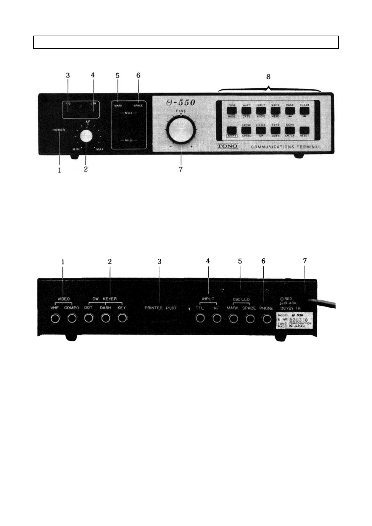
2. LOCATIONS
2-1. Locations
Figure 1. Front Panel
1. Power switch
2. AF Volume Control: controls the volume of a monitor speaker.
3. Figure Indicating LED: indicates Figure case in RTTY.
4. Letter Indicating LED: indicates Letter case in RTTY.
5. Mark Indicating LED: indicates tuning of the mark filter.
6. Space Indicating LED: indicates tuning of the space filter.
7. Fine Tuning Control: Fine adjustment of the shift width while receiving BAUDOT or ASCII.
8. Function Keys: Refer to page 22–23.
Figure 2. Rear Panel
1. Video [VHF]: feeds to a home TV set.
[Composite]: feeds to a video monitor.
2. CW Keyer [Dot]: connects to the dot of iambic operation keyer.
[Dash]: connects to the dash of iambic operation keyer.
[Key]: connects to the keying terminal of the transceiver.
3. Printer Port
4. Input [TTL]: This is an input accepting TTL level of nonmodulated signals in CW, BAUDOT
or ASCII
[AF]: connects to EXT SP terminal of the receiver.
5. OSCILLO [MARK]: connects to the oscilloscope for MARK output of cross hatch.
[SPACE]: connects to the oscilloscope for SPACE output of cross hatch.
6. Phone Jack: connects to an earphone.
7. Power supply cord
4
Page 7
3-1. BASIC SYSTEM
(1) Power Supply
Before connecting a power lead to your DC power supply, make sure that the setting of the
voltage is within the range of 11 – 14 VDC. Observe that the DC source switch and the
POWER switch of the
to a plus (+) terminal of the DC power source; a black power lead to a minus (–) terminal.
(2) TV set and Video Monitor
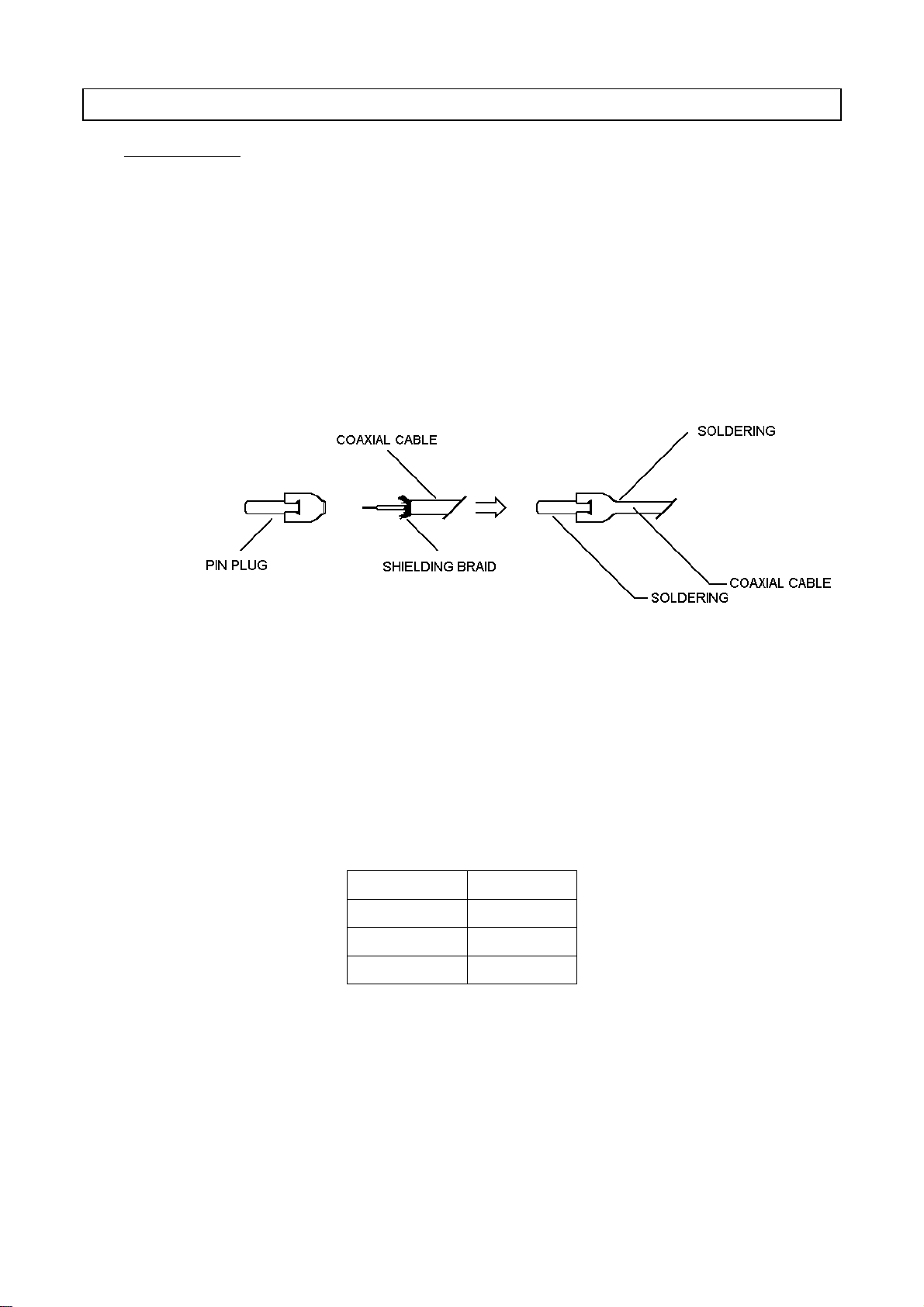
Solder an ancillary coaxial cable and a pin plug as shown in Figure 3. After this procedure,
connect the pin plug to the RF pin jack of the
to an antenna terminal of a home TV set. Tune TV set to CH4. (CH3 in in U.S.A.)
3. CONNECTION
Θ-550
are turned OFF. Then, connect a red power lead of the
Θ-550
and the other end of the coaxial cable
Θ-550
or
Connect the pin plug to COMPOSITE pin jack of the
DISPLAY Model CRT-1200G, which is specially designed for Amateur Radio communications
and offers a very stable display without radio frequency interference.
(3) Receiver
If you desire to use a transceiver for receiption, be sure that SWR is as follows for the proper operation.
Figure 3.
OUTPUT SWR
10 W Maximum 1.5
10 W – 100 W " 1.3
100 W – 500 W " 1.1
Table 1
Θ-550
. We recommend you TONO's CRT
5
Page 8
3-2. EXPANDED SYSTEM
(1) Oscilloscope
The output impedance for Oscilloscope (MARK, SPACE) is 200 kΩ. (Maximum amplitude is
1.2 V
approx.) Large cross hatch is not available when connecting to the oscilloscope
p-p
without horizontal amplifier.
(2) Printer
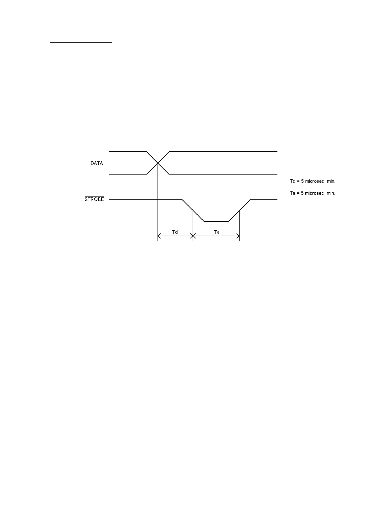
Connect a printer to CN3 pin header on CPU board. Each pin drives a five standard TTL
loads. Avoid overload.
When READY* is Low level, timing of data for printer is as follows:
When READY* is High level, the port for printer holds the previous data.
A printer with Centronics Compatible interface can be connected directly to the
Refer to Figure 12 for Pin Connections.
(3) Squeeze Keyer
Connect the dot terminal of iambic operation keyer to the CW keyer-dot jack of the
Likewise, connect the dash terminal of iambic operation keyer to the CW keyer dash jack of
the
Θ-550
. Then, plug the CW key terminal of the transceiver to the CW keyer-key jack of
the
Θ-550
. Be sure that the CW keyer terminal of the transceiver, which is connected to the
pin side of the pin plug, has the highest voltage.
Figure 4.
Θ-550
.
Θ-550
.
6
Page 9
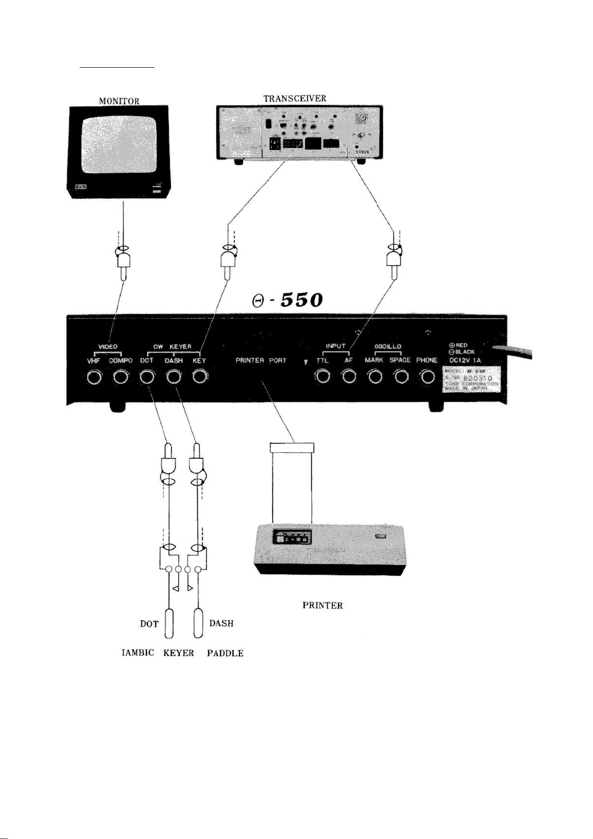
3-3. CONNECTIONS
Figure 5.
7
Page 10
4. PRELIMINARY SETTING
When you unpack your
and check the polarity of the two SUM-3 batteries located in the battery holder) before applying any power
to the
Θ-550
. Insure again that all connections are appropriate.
Apply power, turn the power switch ON in the following order:
1. Video Monitor
2. DC Power Supply
3.
Θ-550
Observe the LTR LED (on the front panel) illuminates.
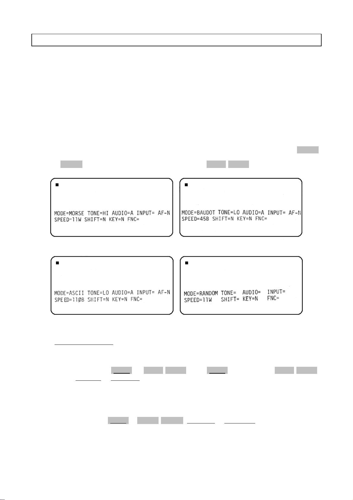
Refer to Figure 6 for an introduction to the monitor screen indicators. Follow the procedure 4-1. thru 4-5. so
that TONE, SHIFT, INPUT, SPEED and SENSE are set automatically even if the mode is changed or [RESET]
key is depressed. Notice that if the setting is not made correctly, the screen indicators are as Figure 6 when
you press [RESET] key. Or Figure 6 thru Figure 9 when you press [TONE]/[MODE].
Θ-550
, be sure that batteries for memory-back-up are secure (remove the top cover
Figure 6. MORSE Figure 7. BAUDOT
Figure 8. ASCII Figure 9. RANDOM GENERATOR
4-1. MORSE (CW) MODE
(1) TONE
By pressing [SHIFT] + [TONE]/[MODE] (hold [SHIFT] down and tap [TONE]/[MODE])
TONE=HI or TONE= LO is displayed alternately on the screen. TONE=HI indicates that the
input frequency of CW is set to 790 Hz. TONE=LO indicates that the input frequency of CW
is set to 395 Hz.
(2) INPUT
By pressing [SHIFT] + [INPUT]/[AUDIO], INPUT=AF or INPUT=TTL is displayed alternately
on the screen. INPUT=AF shows that the input from INPUT AF jack is acceptable.
INPUT=TTL shows that the input from TTL INPUT is acceptable.
8
Page 11

(3) SENSE
With the keystroke [SHIFT] + [SENSE]/[SPEED] followed by [U.S.O.S.]/[UP], INPUT=[]-N or
INPUT=[]-R is displayed alternately. (AF or TTL is shown in [])
INPUT=[]-N shows that NORMAL sense has been selected. INPUT=[]-R shows that
REVERSE sense has been selected.
With the keystroke [SHIFT] + [SENSE]/[SPEED] followed by [SEND]/[DOWN], KEY=N or
KEY=R is displayed alternately.
KEY=N means that the sense of keyer is set to Normal (MARK=ON, SPACE=OFF). KEY=R
means that the sense of keyer is set to REVERSE (MARK=OFF, SPACE ON).
(4) SPEED
Every time [SENSE]/[SPEED] key is depressed, the WPM indication of the speed changes as
the following cycle:
┌> 11 –> 14 –> 18 –> 23 –> 30 –> 39 –> 50 –> 5 –> 6 –> 8 ┐
└────────────────────────────────────────────────────────┘
With a keyboard entry of [U.S.O.S.]/[UP] or [SEND]/[DOWN], fine adjustment of the speed
is available. Note that the screen indicator of WPM remains unchanged even if the speed is
adjusted.
(5) ANTI-NOISE function
Table 2
ANTI-NOISE function is activated or deactivated with the keystroke [CLEAR]/[➠] and
FNC=[]A[][][] (ON) or FNC=[]_[][][] (OFF) is displayed alternately.
(6) How to store the preliminary setting in memory
When you finish the preliminary setting in MORSE mode, hold [SHIFT] down and tap
[WRITE]/[MEMO]. By this process, every parameter are retained according to your stored
setting even if the mode is changed or [RESET] key is depressed.
4-2. BAUDOT (RTTY) MODE
(1) MODE
With the keystroke [TONE]/[MODE], the mode is changed from MORSE to BAUDOT. Screen
indicators are shown in Figure 7.
(2) TONE
By depressing [SHIFT] + [TONE]/[MODE], TONE=HI or TONE=LO is displayed on the screen
alternately. When TONE=HI, the Mark frequency is set to 2125 Hz. When TONE=LO, the
Mark frequency is set to 1275 Hz.
(3) SHIFT
Every time [SHIFT] + [SHIFT]/[CASE] is depressed, SHIFT=N, SHIFT=M or SHIFT=W is displayed on the screen cyclically.
When SHIFT=N, shift width is set to 170 Hz, when SHIFT=M, shift width is set to 425 Hz
and when SHIFT=W, shift width is set to 850 Hz.
9
Page 12
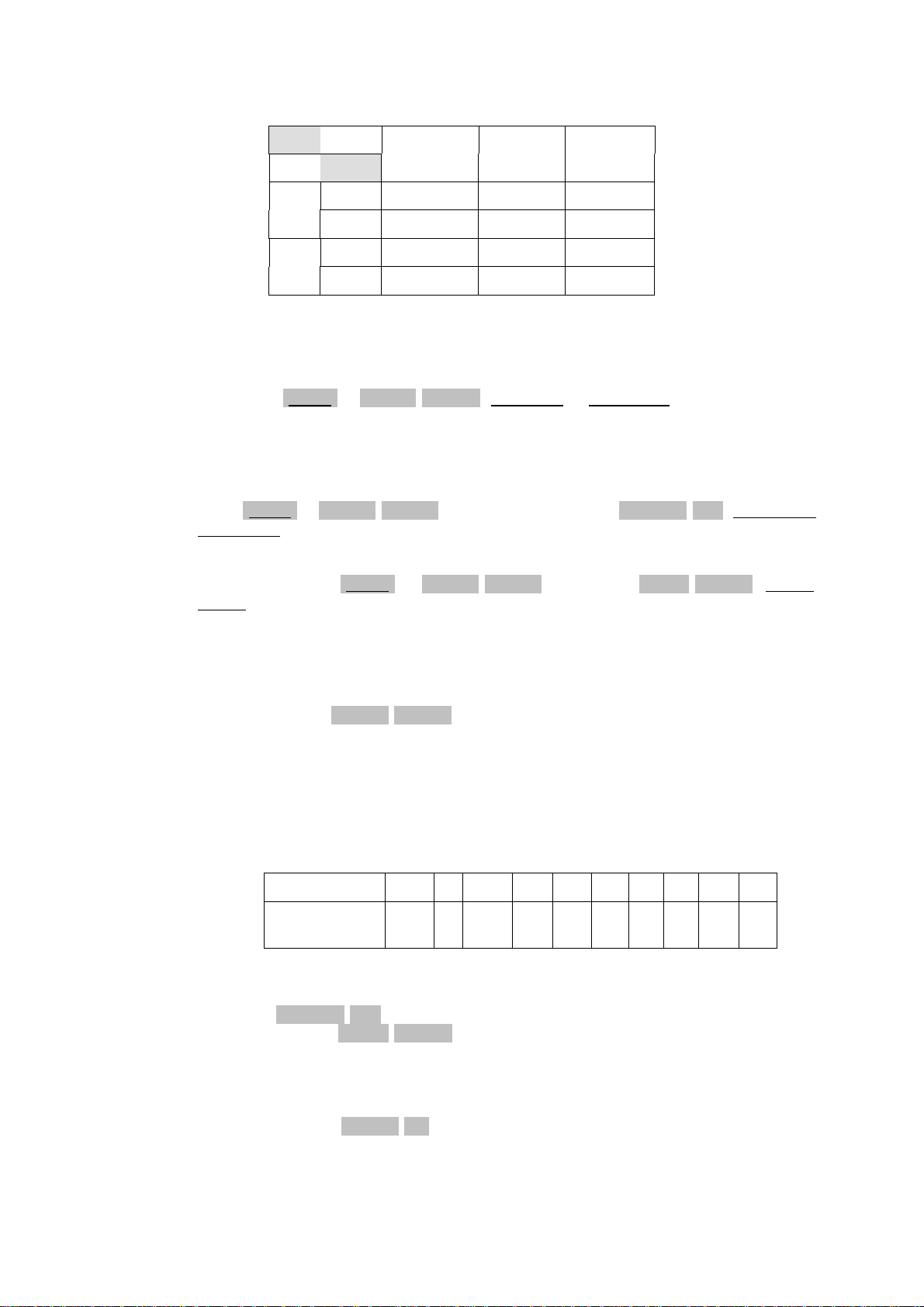
Mark and Space frequency are variable according to the combination of TONE and SHIFT.
(4) INPUT
By pressing [SHIFT] + [INPUT]/[AUDIO], INPUT=AF or INPUT=TTL is displayed alternately.
INPUT=AF shows the input from INPUT AF jack is active. INPUT=TTL shows the input from
INPUT TTL jack is active.
(5) SENSE
When [SHIFT] + [SENSE]/[SPEED] is depressed followed by [U.S.O.S.]/[UP], INPUT=[]-N or
INPUT=[]-R is displayed (AF or TTL is shown in []).
In case of INPUT=[]-N, polarity is NORMAL. In case of INPUT=[]-R, polarity is REVERSE.
SHIFT N M W
TONE (170 Hz) (425 Hz) (850 Hz)
HIGH Mark 2125 Hz 2125 Hz 2125 Hz
Space 2295 Hz 2550 Hz 2975 Hz
LOW Mark 1275 Hz 1275 Hz 1275 Hz
Space 1445 Hz 1700 Hz 2125 Hz
Table 3
With the keystroke [SHIFT] + [SENSE]/[SPEED] followed by [SEND]/[DOWN], KEY=N or
KEY=R is displayed on the screen.
KEY=N indicates the sense of the keyer is set to NORMAL (MARK=ON), SPACE=OFF).
KEY=R indicates the sense of the keyer is set to REVERSE (MARK=OFF, SPACE=ON).
(6) SPEED
Whenever the key [SENSE]/[SPEED] is pressed, the indication of the baud rate changes in
the following sequence:
┌> 45 –> 50 –> 57 –> 74 –> 100 –> 110 –> 150 –> 200 –> 300 –> 600 ┐
└─────────────────────────────────────────────────────────────────┘
The relation between the screen indicators and the actual baud rate is shown in Table 5:
Every time [U.S.O.S.]/[UP] is depressed, the length of 1 bit is shortened by about 136 µsec.
Likewise, whenever [SEND]/[DOWN] is depressed, the length of 1 bit is lengthened by 136
µsec.
Table 4
Indicators 45 50 57 74 100 110 150 200 300 600
Actual baud
45.45 50 56.88 74.2 100 110 150 200 300 600
rate
Table 5
(7) ANTI-NOISE
With the keystroke [CLEAR]/[➠], ON/OFF of ANTI-NOISE is available and FNC=[]A[][][]
(ON) or FNC=[]_[][][] (OFF) is displayed alternately.
10
Page 13

(8) How to store the preliminary setting in memory
When you finish the preliminary setting for BAUDOT mode, hold [SHIFT] down and tap
[WRITE]/[MEMO]. Now, every parameter is retained according to your setting even when
the
Θ-550
is reset or the mode is changed from BAUDOT mode to another.
4-3. ASCII (RTTY) MODE
(1) MODE
With the keystroke [TONE]/[MODE], the mode is changed from BAUDOT to ASCII. Screen
indicators are shown in Figure 8.
(2) TONE
By depressing [SHIFT] + [TONE]/[MODE], TONE=HI or TONE=LO is displayed on the screen
alternately.
TONE=HI shows the Mark frequency is set to 2125 Hz. TONE=LO shows the Mark frequency
is set to 1275 Hz.
(3) SHIFT
Every time [SHIFT] + [SHIFT]/[CASE] is depressed, SHIFT=N or SHIFT=M or SHIFT=W is
displayed on the screen cyclically.
SHIFT=N indicates that shift width of 170 Hz has been selected. SHIFT=M indicates that
shift width of 425 Hz has been selected. SHIFT=W indicates that shift width of 850 Hz has
been selected.
Mark and Space frequency are determined by the combination of TONE and SHIFT as shown
in Table 3.
(4) INPUT
By pressing [SHIFT] + [INPUT]/[AUDIO], INPUT=AF or INPUT=TTL is displayed alternately.
When INPUT=AF, the input from the INPUT AF jack is active. When INPUT=TTL, the input
from the INPUT TTL jack is active.
(5) SENSE
If [SHIFT] + [SENSE]/[SPEED] is depressed followed by the keystroke [U.S.O.S.]/[UP],
INPUT=[]-N or INPUT=[]-R is displayed (AF or TTL is shown in []).
INPUT=[]-N shows that NORMAL polarity has been selected. INPUT=[]-R shows that
REVERSE polarity has been selected.
With the keystroke [SHIFT] + [SENSE]/[SPEED] followed by the keystroke [SEND]/[DOWN],
KEY=N or KEY=R is displayed.
KEY=N indicates that sense of the keyer is Normal (MARK=ON, SPACE=OFF). KEY=R indicates that the sense of the keyer is REVERSE (Mark=OFF, SPACE=ON).
(6) SPEED
By depressing [SENSE]/[SPEED], the indication of the Baud rate is changed in the following
sequence:
┌> 110 –> 150 –> 200 –> 300 –> 600 –> 45 –> 50 –> 57 –> 74 –> 100 ┐
└─────────────────────────────────────────────────────────────────┘
Table 6
The relation between the screen indicators and the actual baud rate is shown in Table 5.
11
Page 14

Be sure that every time [U.S.O.S.]/[UP] is depressed, 1 bit's length is shortened by about
136 µsec. and the keystroke [SEND]/[DOWN] makes 1 bits's length longer by about 136
µsec.
(7) ANTI NOISE function
With the keystroke [CLEAR]/[➠], ANTI-NOISE function is activated or deactivated and
FNC=[]A][][][] (ON] or FNC=[]_[][][] (OFF) is displayed alternately.
(8) How to store the preliminary setting in memory
When the preliminary setting for ASCII mode is completed, [SHIFT] + [WRITE]/[MEMO]
may be depressed. Now each parameter is retained as per your setting even if the
reset or the mode is changed from ASCII to another.
4-4. MORSE CODE RANDOM GENERATOR MODE
(1) MODE
With the keystroke [TONE]/[MODE], the MORSE CODE RANDOM GENERATOR mode is active. Refer to Figure 9 for the screen indicators.
(2) SPEED
Θ-550
is
By pressing [SENSE]/[SPEED], you can change the WPM indication in the following sequence:
┌> 11 –> 14 –> 18 –> 23 –> 30 –> 39 –> 50 –> 5 –> 6 –> 8 ┐
└────────────────────────────────────────────────────────┘
Table 7
The keystroke [U.S.O.S.]/[UP] or [SEND]/[DOWN] covers the fine adjustment of the speed
(Note that the speed indicator on the screen remains unchanged even when the speed is adjusted).
(3) How to store the preliminary setting in memory
When you finish the preliminary setting for speed, press [SHIFT] + [WRITE]/[MEMO]. Then,
the speed is set automatically to your setting whenever the reset key is in this mode is
pressed or the mode is changed from another one to MORSE CODE RANDOM GENERATOR
mode.
4-5. HOW TO MODIFY THE PRELIMINARY SETTING
By depressing [TONE]/[MODE], you can change the mode as the following cycle:
┌> MORSE –> BAUDOT –> ASCII –> RANDOM GENERATOR ┐
└───────────────────────────────────────────────┘
Table 8
Select the mode you desire and modify the preliminary setting in the same manner as explained in each section.
12
Page 15
5. OPERATION
Apply power to 1. Video Monitor
2. DC power
3.
Θ-550
4. Transceiver or Receiver
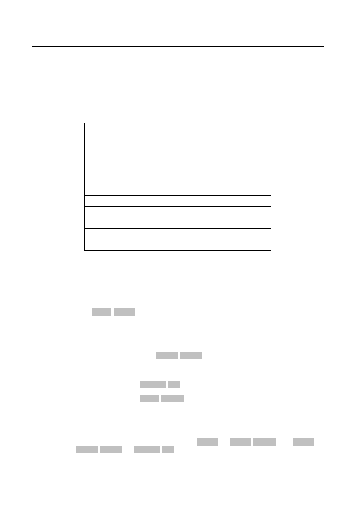
Now LTR LED illuminates and each functions are set as shown below:
MODE
TONE Same as preliminary setting HI (790 Hz)
SHIFT "
SPEED " 11 WPM
INPUT " AF
SENSE " NORMAL
ANTI-NOISE " OFF
ECHO OFF OFF
U.S.O.S. OFF OFF
SEL-CAL OFF OFF
AUDIO AGC AGC
5-1. MORSE MODE
If the preliminary
setting has been made
Same as the last state
before power is removed
Table 9
If the preliminary setting
has not been made
MORSE
(1) MODE SETTING
Press [TONE]/[MODE] key until MODE=MORSE appears on the screen.
(2) SPEED SETTING
Receiving Speed: MORSE Low speed (auto track)
Transmitting speed: Press [SENSE]/[SPEED] repeatedly until WPM of speed indicates the
Fine Adjustment: [U.S.O.S.]/[UP] One dot's length is shorted by 0.8 msec.
(3) INPUT
To apply AF signal from the transceiver to the
INPUT= AF-N. Unless INPUT=AF-N, press [SHIFT] + [INPUT]/[AUDIO] and [SHIFT] +
[SENSE]/[SPEED] –> [U.S.O.S.]/[UP].
speed you desire. Then you are ready to transmit the signal from
squeeze keyer and channel memory.
every time you press it.
[SEND]/[DOWN] One dot's length is lengthened by 0.8 msec.
every time you press it.
Θ-550
, the screen indicator should be as
13
Page 16
(4) TONE
Press [SHIFT] + [TONE]/[AUDIO] so as to get the tone you like. TONE=HI shows the center
frequency of BPF is set to 790 Hz. TONE=LOW shows the center frequency of BPF is set to
395 Hz.
(5) TUNING
a. Using Bar Graph Meter
i) Receive MORSE code with the receiver.
ii) Tune VFO or RIT so that the bar has full length on SPACE side.
b. Using Audio level
i) Press [INPUT]/[AUDIO] key until AUDIO=S is displayed on the screen. In this state,
ii) Tune VFO or RIT of the transceiver so that output level from audio monitor is at
When tuning of the transceiver is completed and Bar Graph Meter follows the MORSE code,
the
Θ-550
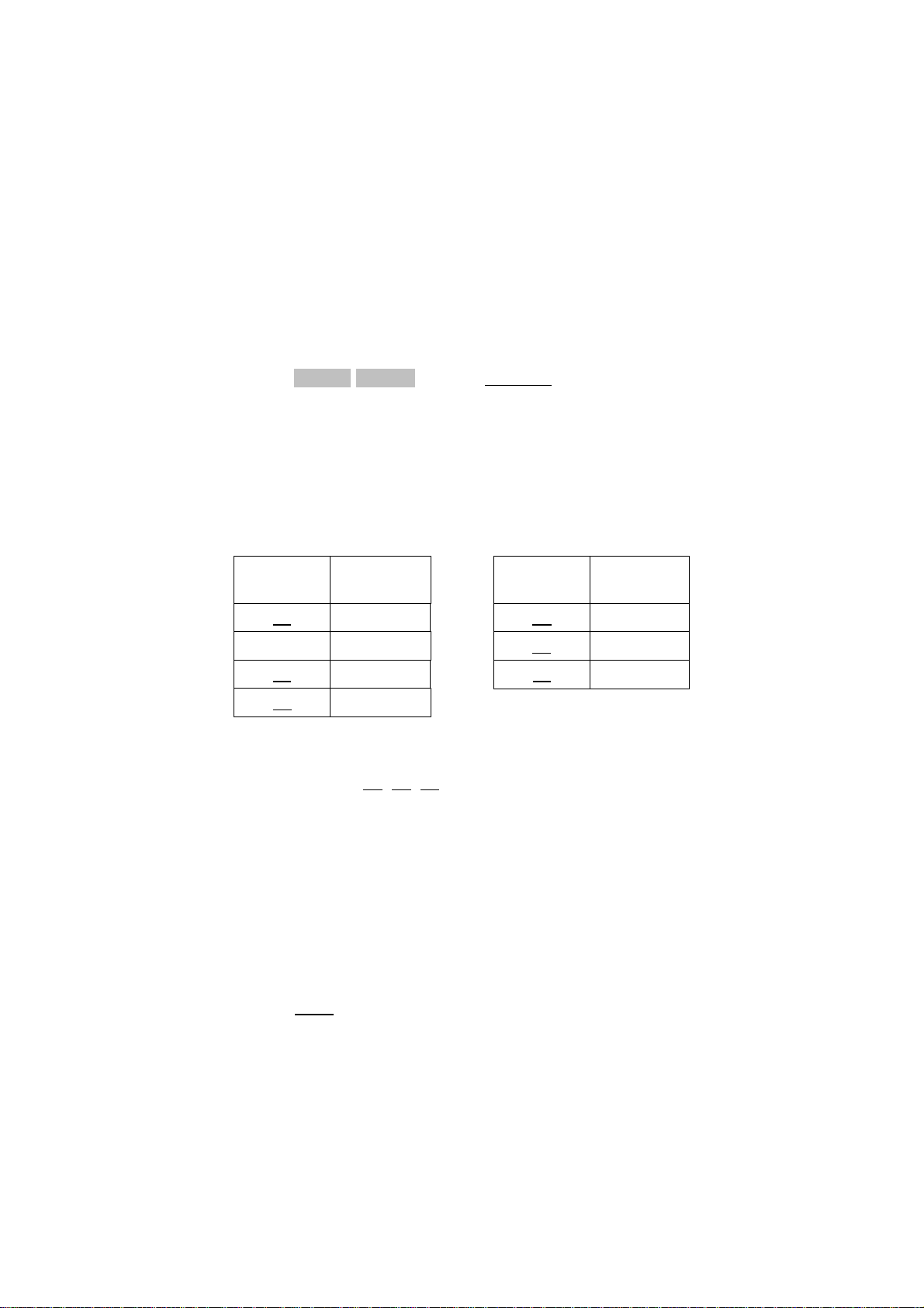
as shown in Table 10.
the filter output for MORSE can be applied to audio monitor.
maximum. Be sure that the SPACE indicating Bar Graph Meter is also its full length.
reads MORSE code and displays on the screen. Special characters are displayed
SPECIAL
CHARACTER
BT = KN (
ERROR < AR +
AS ^ VA ;
AA @
NOTE: Upon receipt of KN, AR, VA, line feed is performed.
(6) How to use Squeeze Keyer
Connect the dot and dash terminal of squeeze keyer paddle to the dot and dash jack of the
Θ-550
respectively. Plug the CW key terminal of the transceiver into the key jack of the
as shown in Figure 5. Now you can enjoy the iambic operation!
550
If you desire to change the speed, follow the procedure mentioned in section (2) SPEED.
The MORSE code you manipulate will display on the screen after the transmit of one character is completed. If there is the combination of dot and dash which is not found in the
MORSE code, space will be added on the screen.
INDICATION
Table 10
SPECIAL
CHARACTER
INDICATION
Θ-
14
Page 17

5-2. BAUDOT MODE
(1) SPEED, TONE AND SHIFT WIDTH SETTING
When the mode is changed to BAUDOT (by pressing [TONE]/[MODE]), SPEED, TONE and
SHIFT WIDTH are set as follows:
If the preliminary
setting has been made
SPEED Same state as preliminary setting 45.45 baud
TONE " Low tone
SHIFT " 170 Hz
Table 11
If you desire a different speed, press [SENSE]/[SPEED] until the required speed is viewed on
the screen. The relation between screen indicator and actual bud rate is shown in Table 5.
Fine adjustment of speed
[U.S.O.S.]/[UP] increases the speed. One keystroke makes 1 bit's length shorter by about
136 µsec. [SEND]/[DOWN] decreases the speed. One keystroke makes 1 bit's length longer
by about 136 µsec.
MARK and SPACE frequency are determined by the combination of TONE and SHIFT WIDTH.
Refer to Table 3.
For amateur communication, 45.45 baud, 170 Hz shift is commonly used; for business communication, 50 baud, 425 Hz shift an 850 Hz shift are popular.
If the preliminary setting
has not been made
(2) TUNING
i) Tune in RTTY signals with the receiver.
ii) Increase the AF output frequency gradually from a lower pitch with the VFO or RIT
iii) Keep increasing the frequency.
iv) Stop increasing the frequency when the MARK indicating Bar Graph Meter begins to
v) SPACE indicating Bar Graph Meter may illuminate at this moment. This shows the
vi) Turn the FINE tuning control and stop it at the maximum indication of the SPACE in-
until MARK indicating Bar Graph Meter begins to flash to its full length.
flash to its full length.
shift width of RTTY signal corresponds to the setting value of the
NO
v)' If SPACE indicating Bar Graph Meter does not illuminate, turn the
FINE tuning control to obtain the position where it illuminates.
NO
vi)' Change the shift setting of the
ing Bar Graph Meter illuminate and turn the FINE tuning control to
make the length of the bar maximum
dicating Bar Graph Meter.
Θ-550
so as to make SPACE indicat-
Θ-550
.
15
Page 18
When tuning is completed, the correct characters will be displayed on the screen. If not:
[INPUT]/[AUDIO] key selects the audio signal from the audio monitor. Every time this key is
depressed, the output of the filter changes as the following cycle:
Mark position monitors output of Mark filter. Space position monitors output of Space filter.
AGC position monitors all incoming audio.
TUNING by Cross-Hatch
In the case of tuning with a cross-hatch made on the oscilloscope, adjust VFO and RIT of a
receiver and the FINE tuning control of the
H-direction the maximum.
5-3. ASCII MODE
Change the speed setting
If NO
Press [SHIFT] + [SENSE]/[SPEED] followed by [U.S.O.S.]/[UP].
If NO
Input signals are not RTTY BAUDOT code.
┌ AGC –> SPACE –> MARK ┐
└──────────────────────┘
Θ-550
to make amplitude both in V-direction and
(1) SPEED, TONE AND SHIFT WIDTH SETTING
When the mode is changed to ASCII mode (by pressing [TONE]/[MODE]), SPEED, TONE and
SHIFT WIDTH are set as follows:
If the preliminary
setting has been made
SPEED Same state as preliminary setting 110 baud
TONE " Low tone
SHIFT " 170 Hz
Table 12
If you desire a different speed, press [SENSE]/[SPEED] until the required speed is viewed on
the screen. The relation between screen indicator and actual bud rate is shown in Table 5.
Fine adjustment of speed
[U.S.O.S.]/[UP] increases the speed. One keystroke makes 1 bit's length shorter by about
136 µsec. [SEND]/[DOWN] decreases the speed. One keystroke makes 1 bit's length longer
by about 136 µsec.
If the preliminary setting
has not been made
TONE is changeable by pressing [SHIFT] + [TONE]/[MODE]. Likewise, SHIFT WIDTH is
changeable by performing [SHIFT] + [SHIFT]/[CASE]. Mark and Space frequency are determined by the combination of TONE and SHIFT WIDTH. Refer to Table 3.
(2) TUNING
Please follow the description at the Baudot mode!
16
Page 19
6-1. ANTI-NOISE CIRCUIT
When there is garbled text causes by noise in the absence of the signal, press [CLEAR]/[➠]. If
FNC=A is viewed on the screen, ANTI-NOISE circuit is activated. Re-depress [CLEAR]/[➠] to release
the function.
6-2. UNSHIFT-ON-SPACE
When weak signals and noise cause errors, press the key [SHIFT] + [U.S.O.S.]/[UP] to activate the
UNSHIFT-ON-SPACE mode. This will cause the terminal to return to the "LETTERS" case upon receipt
of a space signal. Another [SHIFT] + [U.S.O.S.]/[UP] disables the function. FNC=U is displayed
when this function is working.
6-3. ECHO-BACK FUNCTION
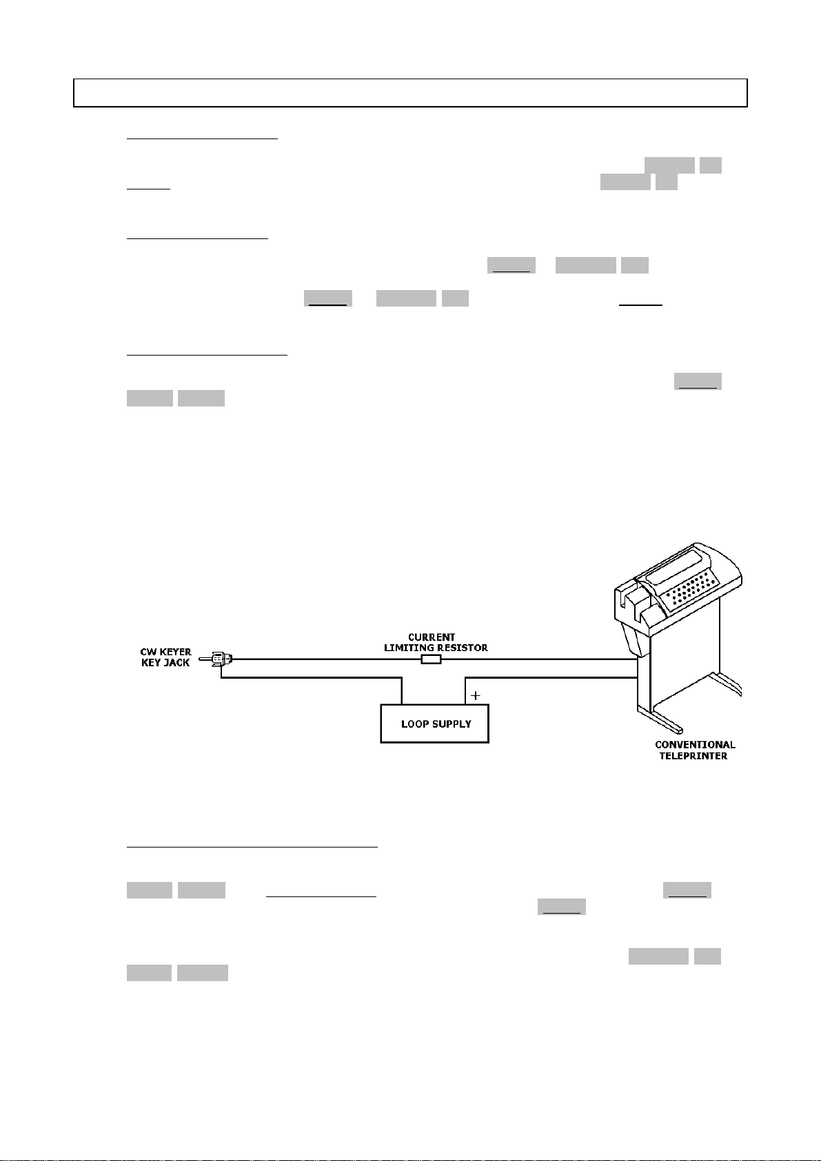
If you desire to connect to the printer with current-loop-type interface, press [SHIFT] +
[ECHO]/[CR/LF] to activate the ECHO-BACK function. Now, the input signal is used for switching the
built-in keyer.
NOTE: It is required that baud rate and code of the printer with current-loop-type interface
corresponds to that of received signal which is usually transmitted directly.
6. SPECIAL FUNCTIONS
Make appropriate connections as Figure 10. Check the polarity and note the maximum voltage and
current of keying circuit to select proper LOOP SUPPLY and CURRENT LIMITING RESISTOR.
6-4. MORSE CODE RANDOM GENERATOR
Generates 5-characters-sequence, random MORSE code. To activate this function, continue to press
[TONE]/[MODE] until MORSE=RANDOM is seen on the screen. With the keystroke [SHIFT], the
Θ-550
begins to generate MORSE code. Another keyboard entry of [SHIFT] releases this function.
Figure 10
If you desire to change the speed, [SENSE]/[SPEED] should be depressed until your required speed
is on the screen. Fine adjustment of the selected speed is available with [U.S.O.S.]/[UP] or
[SEND]/[DOWN].
17
Page 20

6-5. MORSE PRACTICE
Connect the straight key to INPUT-TTL jack. By pressing [TONE]/[MODE] key, set the mode to
MORSE and by pressing [SHIFT] + [INPUT]/[AUDIO], set the input switch to TTL. Manipulate the
key so that the reading is displayed on the screen. Monitor sound can be heard by operating ECHOBACK function.
6-6. RECORDING OF RECEIVED SIGNALS
Recording while receiving is available by connecting PHONE jack of the
minal of a tape recorder.
6-7. AUTOMATIC CR/LF AFTER RECEIVING
In several seconds after completion of receiving messages CR/LF is performed on the screen. CR/LF
signal is also sent to the printer port automatically.
6-8. WORD-WRAP-AROUND
The
Θ-550
has a special Word-Wrap-Around feature which prevents the splitting of a word an the
screen.
6-9. SEND FUNCTION
Message written on the screen by using squeeze keyer or message loaded from the cassette tape recorder to the screen can be sent as an entire page. To activate this function, press [SHIFT] +
[SEND]/[DOWN]. Be sure that selected range for "SEND" function is from the top of the screen to
where the cursor is placed.
To interrupt the transmission, press any key except [RESET].
Θ-550
to the microphone ter-
18
Page 21

7. MEMORY CHANNEL PROGRAMMING AND USE
The
Θ-550
contains 9 different, non volatile memory channels as below:
1. CH1 ........... 23-characters Message Memory for transmit
2. CH2 ........... "
3. CH3 ........... "
4. CH4 ........... "
5. CH5 ........... ID memory for "QBF" transmit (23 characters)
6. CH6 ........... "SEL-CAL Characters" for local station (23 characters)
7. CH7 ........... "End of Text" for local station (23 characters)
8. CH8 ........... "SEL-CAL Characters" for distant station (23 characters)
9. CH9 ........... "End of Text" for distant station (23 characters)
7-1. PROGRAMMING
(1) Press the key [WRITE]/[MEMO]
(2) Depress any of the key below according to the channel number you desire to program:
CH1 .... [TONE]/[MODE] CH6 .... [SENSE]/[SPEED]
CH2 .... [SHIFT]/[CASE] CH7 .... [U.S.O.S.]/[UP]
CH3 .... [INPUT]/[AUDIO] CH8 .... [SEND]/[DOWN]
CH4 .... [PAGE]/[➟] CH9 .... [ECHO]/[CR/LF]
CH5 .... [CLEAR]/[➠]
NOTE: The selected channel number is indicated at the last column of the function indica-
tion.
FNC= [][][][] _
(3) With the keystroke [SHIFT] + [WRITE]/[MEMO], the WRITE mode is active. Note that the
alpha-numeric and symbols are indicated as
♣
BCDEFGHIJKLMNOPQRSTUVWXYZ0123456789 _______
!"#$%&'()*+,-./:;<=>?@[\]^_CL _____________
(4) By pressing [PAGE]/[➟] or [CLEAR]/[➠], move the cursor to the character which you desire
to store in the channel memory. If you desire to add space, move the cursor to the place
anywhere the underline shown in (3) is drawn.
(5) With the keystroke [SHIFT] + [WRITE]/[MEMO], chosen characters are indicated on the
screen.
(6) The keystroke [INPUT]/[AUDIO] enables to delete the miswritten character one by one from
the end.
(7) Repeat the procedure (3) thru (5) to complete to edit your message or ID. Be sure that a ca-
pacity characters of CH1 ~ CH9 is 23 long.
(8) When you finish editing your message or ID, press [WRITE]/[MEMO] to store in the channel
memory. At the same time, this function may be released.
<-- SPACE
<-- SPACE
19
Page 22

7-2. TRANSMISSION
7-2-1. CH1 ~ CH4 (Message Memory)
(1) Press the key [WRITE]/[MEMO].
(2) If you press any of the key below according to the channel number you desire to transmit,
the channel number is indicated at the last column of the function indication.
CH1 .... [TONE]/[MODE] CH3 .... [INPUT]/[AUDIO]
CH2 .... [SHIFT]/[CASE] CH4 .... [PAGE]/[➟]
(3) The stored message can be transmitted by pressing [SHIFT] + [SEND]/[DOWN].
(4) You may interrupt the transmission at any time by pressing any of the keys except [RESET].
7-2-2. CH5 ("QBF" Memory)
(1) Press [WRITE]/[MEMO].
(2) With the keystroke [CLEAR]/[➠], [SHIFT] + [SEND]/[DOWN], the following test message is
transmitted:
THE QUICK BROWN FOX JUMPS OVER THE LAZY DOG DE ________
(3) Any of the key except [RESET] may interrupt the transmission.
7-2-3. CH6 ~ CH9 (Selective Calling Memory)
(1) Press the key [WRITE]/[MEMO].
(2) Press any of the key below according to the channel number you desire to transmit:
CH6 ("SEL-CAL Characters" of local station) ..... [SENSE]/[SPEED]
CH7 ("End of Text" of local station) ................. [U.S.O.S.]/[UP]
CH8 ("SEL-CAL Characters" of distant station ... [SEND]/[DOWN]
CH9 ("End of Text" of distant station) ............. [ECHO]/[CR/LF]
(3) The stored "SEL-CAL Characters" or "End of Text" are transmitted with the keystroke
[SHIFT] + [SEND]/[DOWN].
(4) Any of the keystroke except [RESET] can interrupt the transmission.
the identification written in CH5
➈
20
Page 23

8. SELECTIVE CALLING SYSTEM
SEL-CAL mode is activated with a keyboard entry of [PAGE]/[➟]. Make sure that S is indicated at the fourth
column of the function indication on the screen.
FNC=[][][]S[]
NOTE: When the data for "SEL-CAL Characters" and "End of Text" is not provided in the channel
memory, SEL-CAL mode will not be activated even if the above key pressed.
8-1. SEL-CAL OF LOCAL STATION
When using SEL-CAL mode, the received message are not indicated on the screen nor printed out to
the printer until "SEL-CAL Characters" of local station (written in CH6) is received. Receipt of this
"SEL-CAL Characters" causes the display and printing of messages.
After receiving "SEL-CAL characters", FNC=E is displayed and Echo-Back function is available. The
same signal as input is transmitted from the key jack.
Once "End of Text" of local station (written in CH7) is received, the
sages any more. Another [PAGE]/[➟] can release the function.
8-2. SEL-CAL OF DISTANT STATION
With the keystroke [WRITE]/[MEMO] followed by [SEND]/[DOWN] and [SHIFT] + [SEND]/[DOWN],
"SEL-CAL Characters" of distant station (written in CH8) can be transmitted. (This signal will open
the SEL-CAL system of the distant station.) Your message may be sent after this process.
Press [WRITE]/[MEMO]➠[ECHO]/[CR/LF]➠[SHIFT] + [SEND]/[DOWN] to transmit "End of Text"
of distant station (written in CH9) when you complete the transmission.
Θ-550
can not accept the mes-
21
Page 24
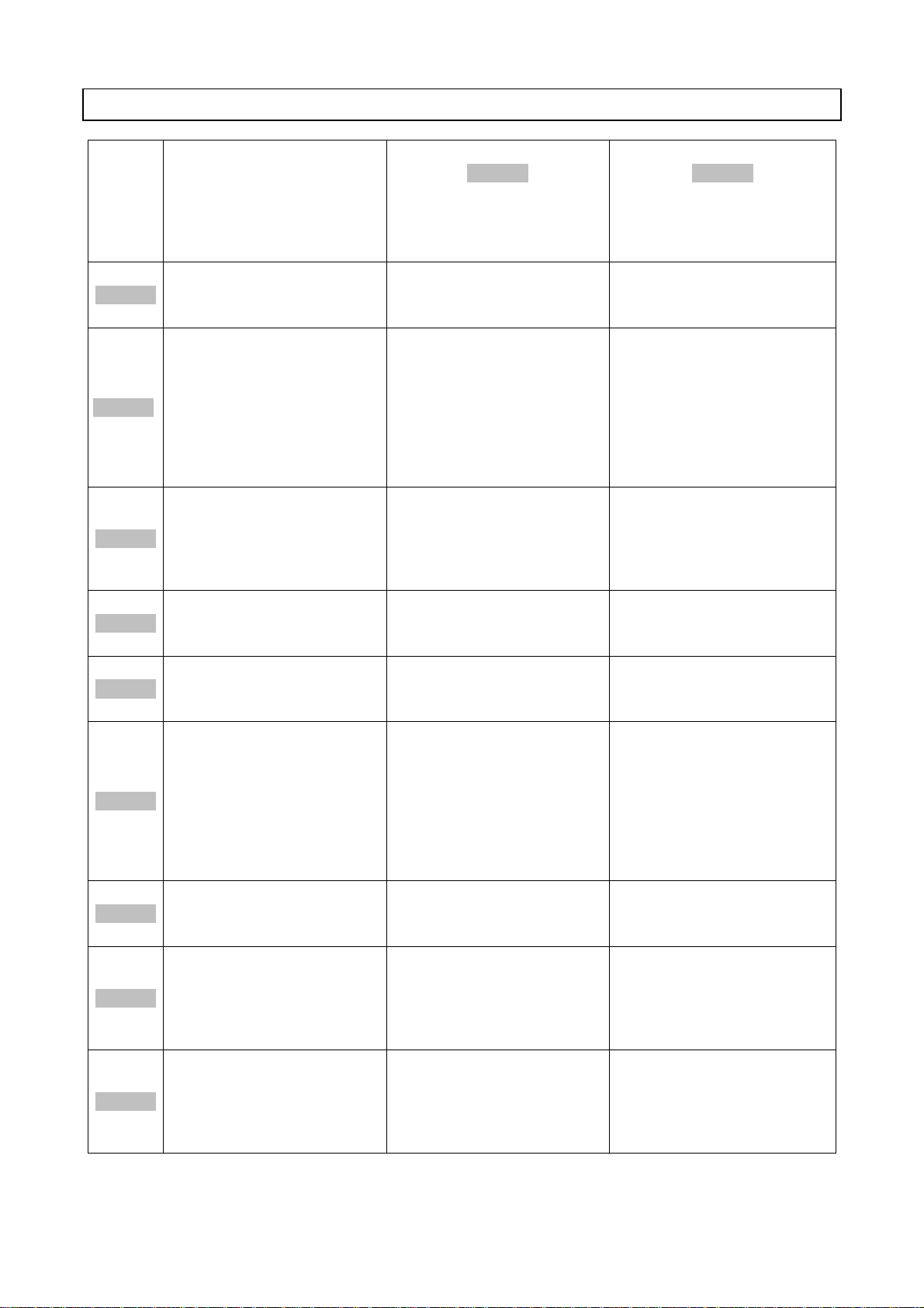
KEY UNSHIFT
9. APPENDIX
[ ]
SHIFT
WRITE
[ ]
MEMO
[ ]
RESET
[ ]
SHIFT
TONE
[ ]
MODE
SHIFT
[ ]
CASE
INPUT
[ ]
AUDIO
(Hold this key down and tap
the following key)
Initializes the microprocessor Initializes the microprocessor Initializes the microprocessor
When you hold this key down
and tap any other key except
[RESET], the upper side of the
function becomes active. In
MORSE RANDOM GENERATOR
mode start/stop of random
MORSE code is available by
pressing and release this key.
Selects the mode. Every time
this key is pressed, the mode
is changed cyclically as MORSE
➠
BAUDOT ➠ ASCII ➠ MORSE
RANDOM GENE.
In BAUDOT mode, the case of
LETTERS/FIGURES is switchable with the keystroke.
Monitors output of AGC filter,
SPACE filter and MARK filter.
Selects the input frequency
Changes the shift width of
tone pair in BAUDOT and
ASCII mode.
Selects AF input or TTL input.
----- -----
(After pressing the above, tap
the following key)
Selects CH1
(message memory)
Selects CH2
(message memory)
Selects CH3
(message input)
WRITE
[ ]
MEMO
PAGE
[ ]
CLEAR
[ ]
SENSE
[ ]
SPEED
Press this key prior to writing
or reading the data in CH1 ~
CH9.
Moves the cursor to left when
the message memory programming mode is active.
Allows to activate or deactivate ANTI-NOISE function.
Moves the cursor to right
when the message memory
programming mode is active.
Changes the speed of squeeze
keyer in MORSE mode. Also
changes transmit/receive
speed in BAUDOT and ASCII
mode.
Modifies the states of TONE,
SHIFT etc. to the one written
on the screen when the
is reset or the mode is
changed. If the message
memory is selected, this keystroke activates message
memory programming mode.
Changes the page of the
screen.
Clears the screen
Inverts the polarity of
MARK/SPACE input and
MARK/SPACE output separately.
Θ-550
Causes the storage of edited
message and deselects the
message memory.
Selects CH4
(message memory).
Selects CH5
(ID memory for "QBF")
Select CH7
(ID memory for "SEL-CAL Char-
acters" of local station)
22
Page 25
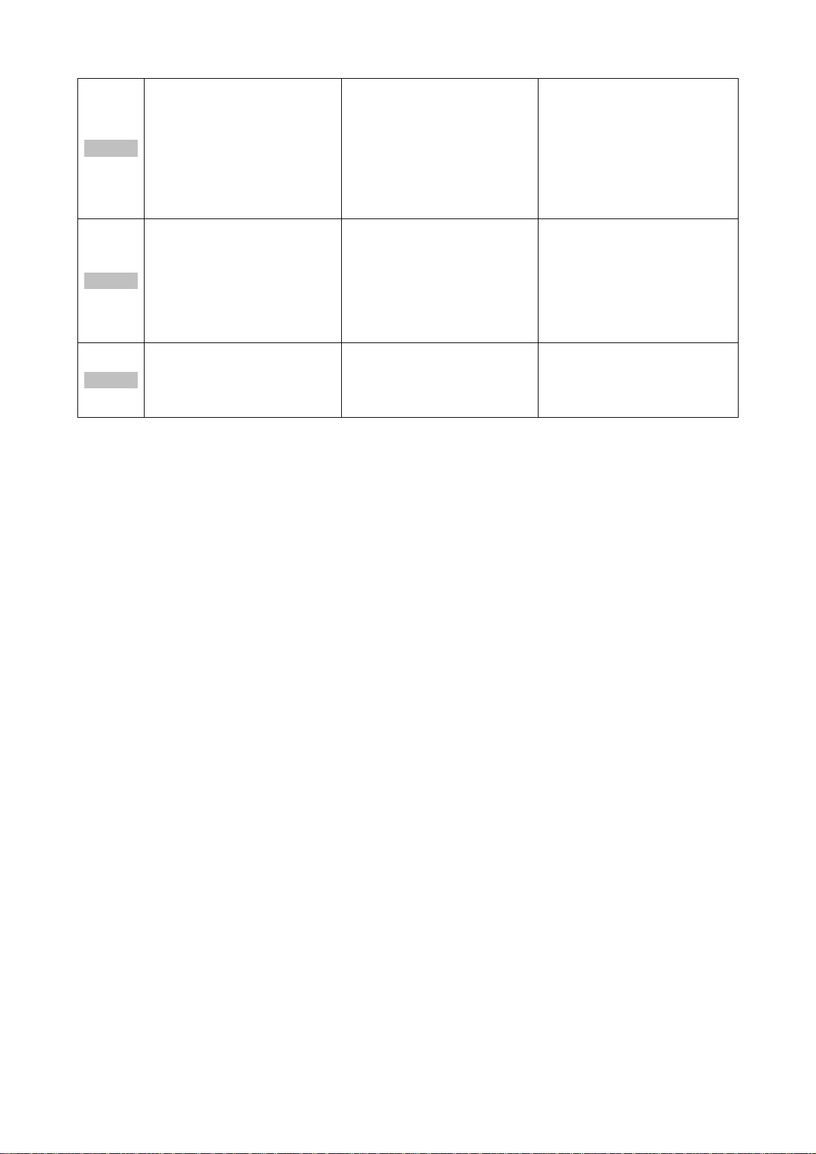
U.S.O.S.
[ ]
UP
Makes a fine adjustment of the
selected speed. One keystroke
makes the length of one bit
shorter by 0.8 msec. in MORSE
mode. In BAUDOT and ASCII
mode, one keystroke makes
the length of one bit shorter
by 136 µsec.
Allows to activate or deactivate UNSHIFT-ON-SPACE function.
Selects CH7
(ID memory for "End of Text"
of local station)
SEND
[ ]
DOWN
ECHO
[ ]
CR/LF
Makes a fine adjustment of the
selected speed. Every time it is
pressed, one bit's length is
lengthened by 0.8 msec. in
MORSE mode an 136 µsec. in
BAUDOT and ASCII mode.
Moves the cursor to the head
of the next line.
Provides CR/LF command output to the printer port.
Activates "SEND" function and
transmits the message displayed on the screen. When
the message memory channel
is selected, the message
stored in that channel is transmitted.
With this keystroke, "ECHOBACK" function is activated
and released.
Select CH8
(ID memory for "SEL-CAL Char-
acters" of distant station).
Selects CH9
(ID memory for "End of Text"
of distant station)
23
Page 26
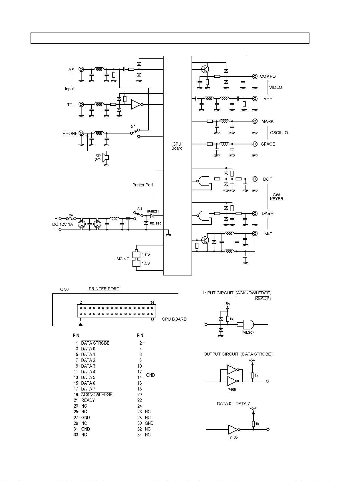
Figure 11 INPUT/OUTPUT CIRCUIT
24
Page 27
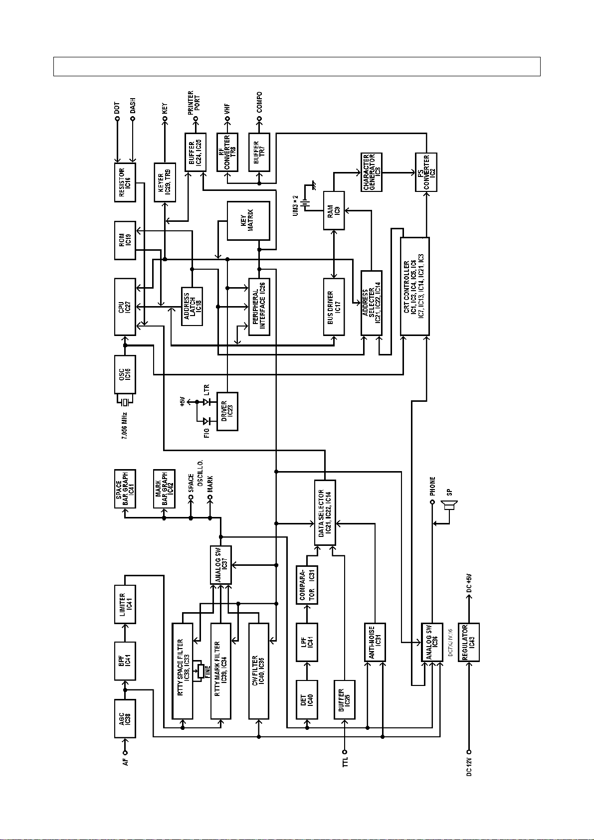
Figure 12 BLOCK DIAGRAM
25
Page 28
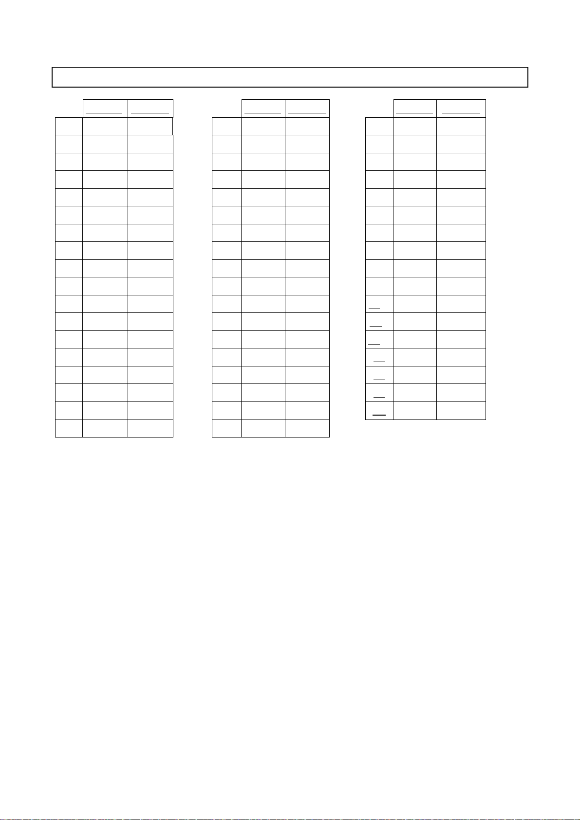
CW (MORSE) CODE
DISPLAY SIGNALS DISPLAY SIGNALS DISPLAY SIGNALS
A A
B B
C C
D D
E E
F F
G G
H H
I I
J J
K K
L L
M M
N N
O O
P P
·–
–···
–·–·
–··
·
··–·
––·
····
··
·–––
–·–
·–··
––
–·
–––
·––·
S S
T T
U U
V V
W W
X X
Y Y
Z Z
1 1
2 2
3 3
4 4
5 5
6 6
7 7
8 8
···
–
··–
···–
·––
–··–
–·––
––··
·––––
··–––
···––
····–
·····
–····
––···
–––··
, ,
. .
: :
? ?
/ /
- -
" "
) )
' '
BT,= =
KN,( (
AR,+ +
AA @
AS ^
SK ;
·––––·
·–·–·–
–––···
··––··
–··–·
–····–
·–··–·
–·––·–
·––––·
–···–
–·––·
·–·–·
·–·–
·–···
···–·–
Q Q
R R
––·–
·–·
9 9
Ø Ø
––––·
–––––
HH <
········
26
 Loading...