

Page 1

TONO
COMMUNICATIONS COMPUTER
Θ - 350
INSTRUCTION MANUAL
TONO CORPORATION
98 MOTOSOJA-MACHI, MAEBASHI-SHI, 371. JAPAN
Page 2

TABLE OF CONTENTS
1. PRECAUTIONS ................................................................ 1
2. FEATURES ....................................................................... 2
3. LOCATION AND FUNCTION CONTROLS ....................... 3
4. ACCESSORIES SUPPLIED ............................................. 5
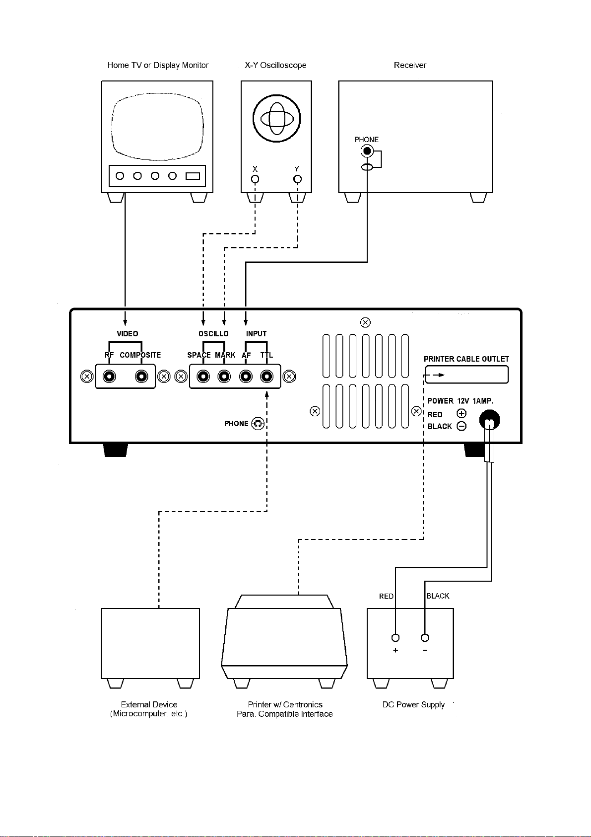
5. CONNECTION .................................................................. 5
BASIC SYSTEM ................................................................ 5
i) Power Supply
ii) TV set
iii) Receiver
EXPANDED SYSTEM ....................................................... 6
i) Oscilloscope
ii) Printer
6. OPERATION ..................................................................... 8
i) Preliminary Setting .................................................... 8
ii) Procedure to Power Up Equipment ........................... 8
iii) CW (Morse) Operation ............................................... 9
iv) RTTY (Baudot) Operation ......................................... 10
v) ASCII Operation ........................................................ 12
vi) Special Functions ...................................................... 12
7. MAINTENANCE .................................................................14
8. SPECIFICATION ............................................................... 15
9. I/O CIRCUIT ...................................................................... 16
Page 3

TONO Θ-350 INSTRUCTION MANUAL
1. PRECAUTION
1. Before operating the set, please read this INSTRUCTION MANUAL thoroughly.
2. Take care to properly connect in the connection to the input circuits and output circuits. Input
signal and load should be within the ratings.
3. Voltage of DC power supply should be within the range of DC 11 V --- 14 V.
4. When the input impedance of the TV set is 300 ohms, (not 75 ohms) put a matching transformer of 75 ohms : 300 ohms between the Theta-350 and the TV set.
5. The Theta-350 should be installed at a well-ventilated dry place not exposed to the direct rays
of the sun with special care for heat radiation.
6. Built-in demodulator can be used with 150 Baud maximum.
1
Page 4

TONO Θ-350 INSTRUCTION MANUAL
2. FEATURES
1. Communications Computer Θ-350
Due to the most up-to-date computer technology, one piece of equipment can now handle receiving in CW, RTTY and ASCII.
2. VHF and Composite video output provided
Both a home TV set and video monitor outputs are provided for display purposes.
3. Printer interface
Centronics para. Compatible interface enables easy connection of a low-cost dot printer for
hard copies. Can be connected directly with HC-800 & HC-900.
4. Wide range of receiving speeds
Automatic CW speed adjustment and 8 Communication speeds for RTTY and ASCII. The multiple speed feature makes the Θ-350 ideal for Amateur, business and commercial use.
5. Built-in demodulator for high performance
Three-step shift (either 170 Hz, 425 Hz, 850 Hz) can be obtained using either High Tones or
Low Tones. Manual adjustment is available by FINE TUNING Control.
6. Anti-Noise
A new anti-noise circuit prevents garbled message when there is no signal.
7. Large capacity display memory
The two-page display memory contains 32 characters × 16 lines per page. Page selection is
operated via the keyboard.
8. WORD-WRAP-AROUND function
Word-wrap-around prevents the last word of the line from splitting in two.
9. MARK-AND-BREAK (SPACE-AND-BREAK) system
Either mark or space tone can be used to copy RTTY.
10. Monitor circuit
A built-in monitor circuit with an automatic receive switch enables checking of the receiving
state. It is possible to check the output of the mark filter, the space filter and AGC amplifier prior
to the filters.
11. CW practice function
The Θ-350 reads data from the key and displays the characters on the screen.
12. Cross-pattern checking output terminal
Provision has been made for attachment of an oscilloscope to aid tuning. This supplements the
tuning LED and audio monitor provided in the system.
2
Page 5
TONO Θ-350 INSTRUCTION MANUAL
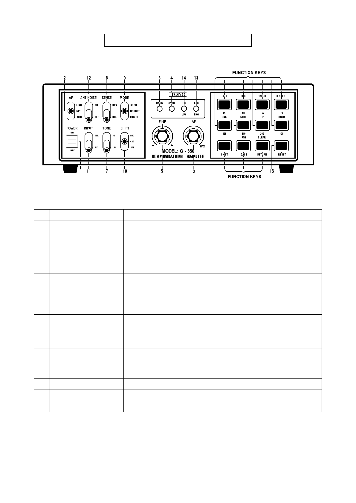
3. LOCATION AND FUNCTION CONTROL
Fig. 1
i) FRONT PANEL
No. Name Function
1 POWER switch
2 AF switch
[AGC] output from AGC can be monitored.
[MARK] or [SPACE] output from respective filters can be monitored
3 AF volume control Controls the volume of a monitor speaker
4 SPACE indicating LED Indicates space of input signal
5 FINE tuning control
Provides the fine tuning of shift width in receiving in BAUDOT and
ASCII mode
6 MARK indicating LED Indicates mark of input signal
7 TONE switch Indicates High Tone or Low Tone in BAUDOT and ASCII mode
8 SENSE switch Changes the polarity of MARK/SPACE in input
9 MODE switch For mode selection
10 SHIFT switch Sets the shift width in BAUDOT and ASCII mode
11 INPUT switch
[TTL] obtains input from INPUT TTL jack
[AF] obtains input from INPUT-AF
12 ANTI-NOISE switch Helps to prevent garble when there is no signal
13 LETTER indicating LED Indicates Letter case in RTTY
14 FIGURE indicating LED Indicates Figure case in RTTY
15 RESET key Put the set in the initial state
Table 1
3
Page 6
TONO Θ-350 INSTRUCTION MANUAL
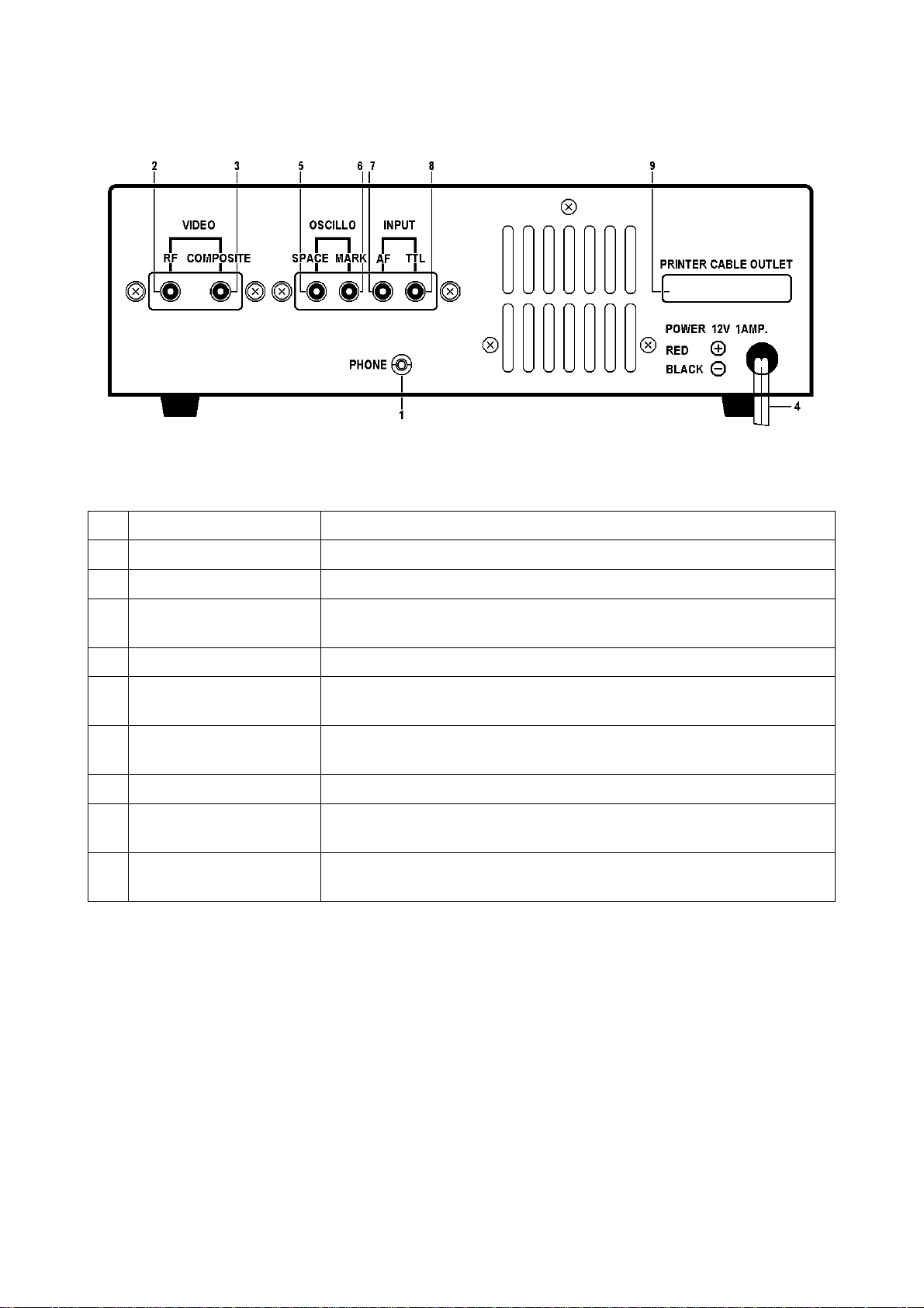
Fig. 2
ii) BACK PANEL
No. Name Function
1 PHONE jack Connect with an earphone
2 VIDEO RF jack Connect with a home TV set
VIDEO COMPOSITE
3
jack
Connect with a video monitor
4 POWER supply cord DC 12 V in
5 OSCILLO SPACE jack Oscilloscope should be connected to this jack for space output for
cross-pattern.
6 OSCILLO MARK jack
Oscilloscope should be connected to this jack for mark output for
cross-pattern.
7 INPUT-AF jack Connect to EXT SP terminal or line output of the receiver
8 INPUT-TTL jack
For non-modulated signals in CW, BAUDOT or ASCII and when
using with a hand key.
9 PRINTER CABLE
OUTLET
Table 2
4
Page 7
TONO Θ-350 INSTRUCTION MANUAL
4. ACCESSORIES SUPPLIED
Instruction Manual ............... 1
Pin Plug .............................. 4
Earphone Plug .................... 1
Coaxial Cable ..................... 4 m
5. CONNECTION
BASIC SYSTEM
i) Power Supply
Before connecting a power lead to your DC power supply, the setting of the voltage must be
within the range of DC 11 V – 14 V. After confirming that that the DC source switch and the
POWER switch of the Θ-350 indicates OFF, connect a red power lead of the Θ-350 to a
plus (+) terminal of the DC power source; a black power lead to a minus (–) terminal.
ii) TV Set
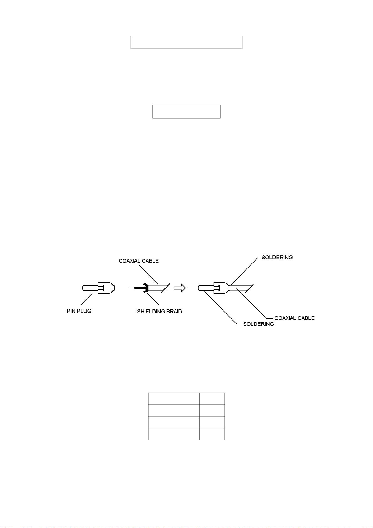
1. Solder an ancillary coaxial cable and a pin plug as shown in Fig. 3. After having sol-
or 2. Connect the pin plug to COMPOSITE pin jack for a display monitor.
iii) Receiver
If you use a transceiver for receiver, make sure SWR is as flows to enable correct operation:
dered, connect the pin plug to the RF pin jack of the Θ-350 and the other end of the
coaxial cable to an antenna terminal of a home TV set. Tune TV set to CH 4 (CH 3
in USA).
OUTPUT SWR
10 W --- 1,5
10 W – 100 W --- 1.3
100 W – 500 W --- 1.1
Table 3
5
Page 8
TONO Θ-350 INSTRUCTION MANUAL
EXPANDED SYSTEM
i) Oscilloscope
Output impedance for oscilloscope is 200 kΩ. Use an oscilloscope of which input impedance
is over 1 MΩ. Output for oscilloscope is about 1.2 V
. Large cross pattern is not obtain-
p-p
able without amplifier in Horizontal amplifier of the oscilloscope.
ii) Printer
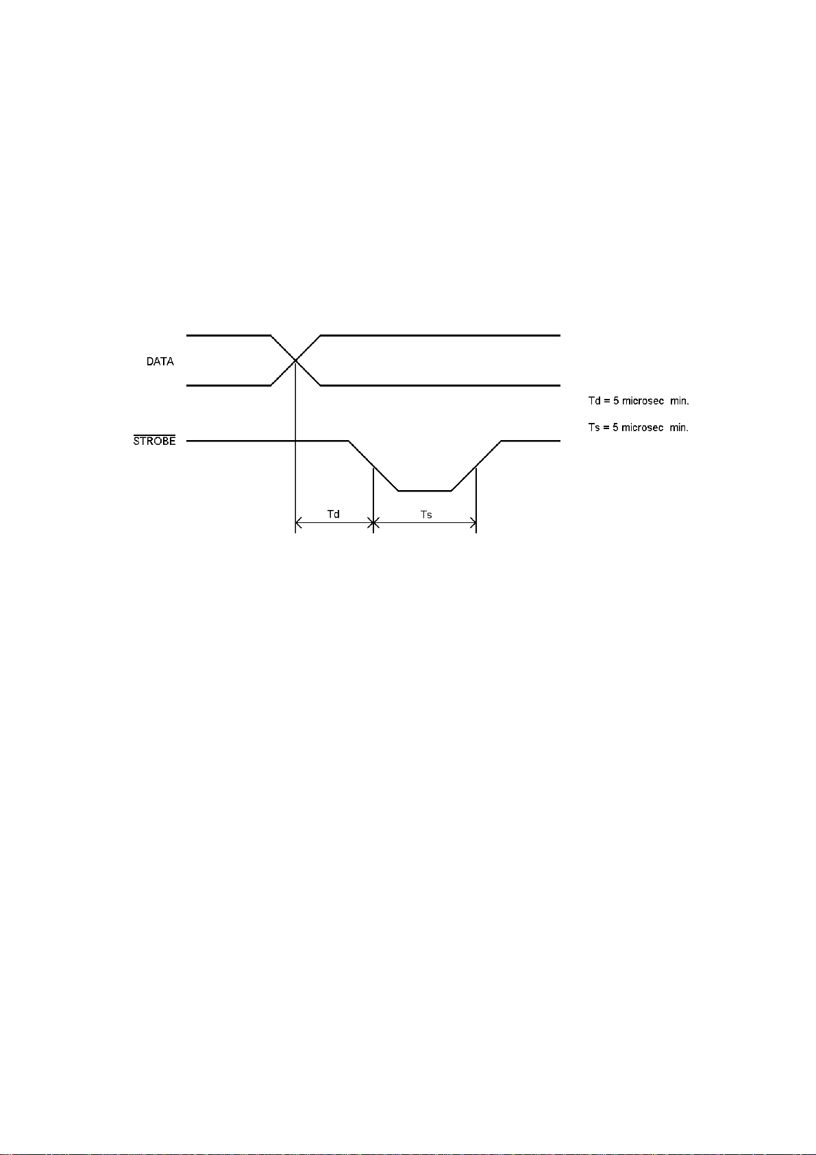
Connect a printer to CN6 pin header on CPU board. The fan-out of each pin is 5 standard
TTL loads. Avoid overload. When READY* is "L" level, timing of data for printer is as follows:
Fig. 4
When READY* is "H" level, the port for printer holds previous data.
Any printer with centronics Compatible interface can be connected directly with the Θ-350.
We recommend the TONO Dot Matrix Serial Impact Printer model HC-800 and HC-900,
which are easy to connect by its special cable connector for the Θ-350. (Refer to page 16.)
6
Page 9
TONO Θ-350 INSTRUCTION MANUAL
Fig. 5
7
Page 10
TONO Θ-350 INSTRUCTION MANUAL
6. OPERATION
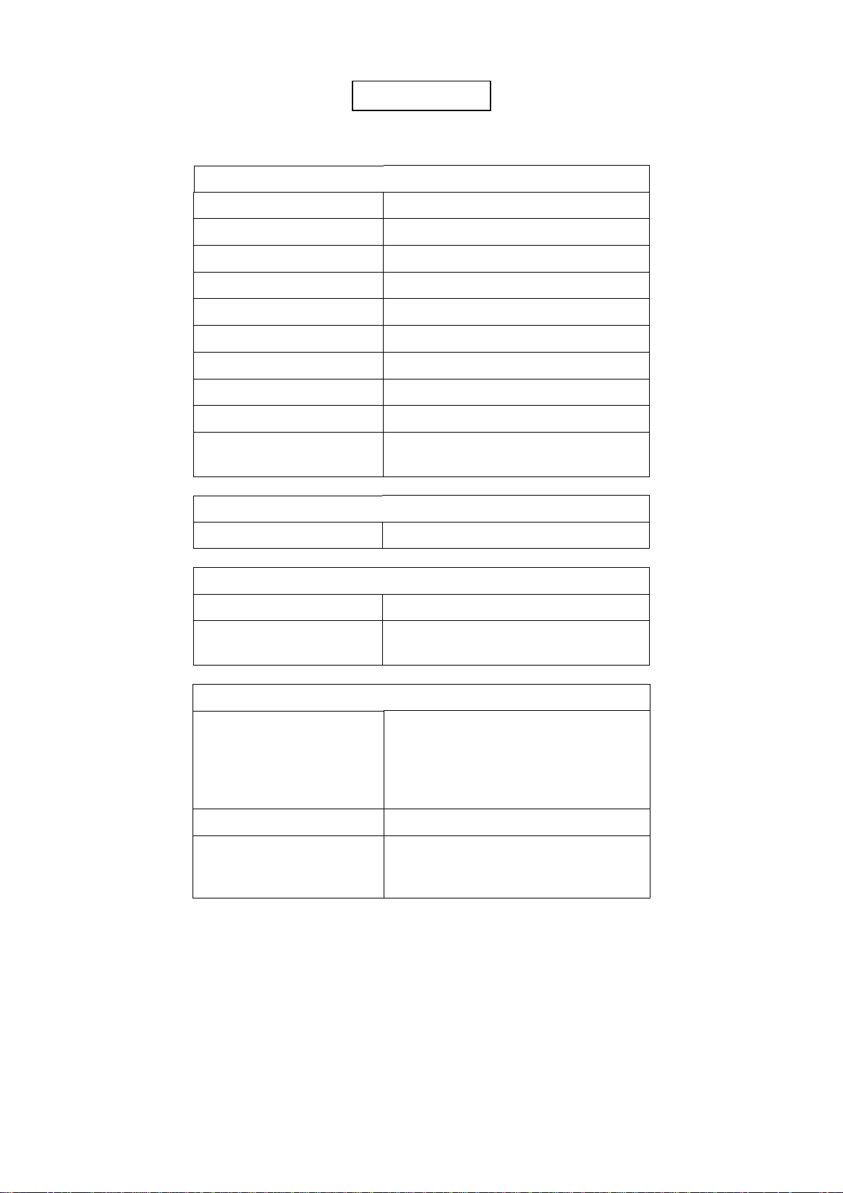
i) Preliminary Setting
Θ-350
POWER sw OFF
AF vol. Medium
MODE sw {as required}
SENSE sw NORM
ANTI-NOISE sw {as required}
INPUT sw AF
AF sw AGC
FINE tuning control Medium
TONE sw {as required}
SHIFT sw
(any place) When in BAUDOT mode,
select the proper shift.
DC Power Supply
POWER sw OFF
TV set
POWER sw OFF
VHF Channel (home TV)
CH4 (Australia & Continental)
CH3 (USA)
Transceiver (Receiver)
According to the MODE sw setting of
the Θ-350
MODE sw
w/o FSK function LSB setting is required for RTTY
POWER sw OFF
Set it so as to make the input voltage
AF volume
into the Θ-350 ranging from 50 mV to
1 V. (ordinary listing volume)
ii) Procedure to power up equipment
Put the power switch ON of: 1. TV set
2. DC power supply
3. Θ-350
4. Transceiver
Table 4
8
Page 11
TONO Θ-350 INSTRUCTION MANUAL
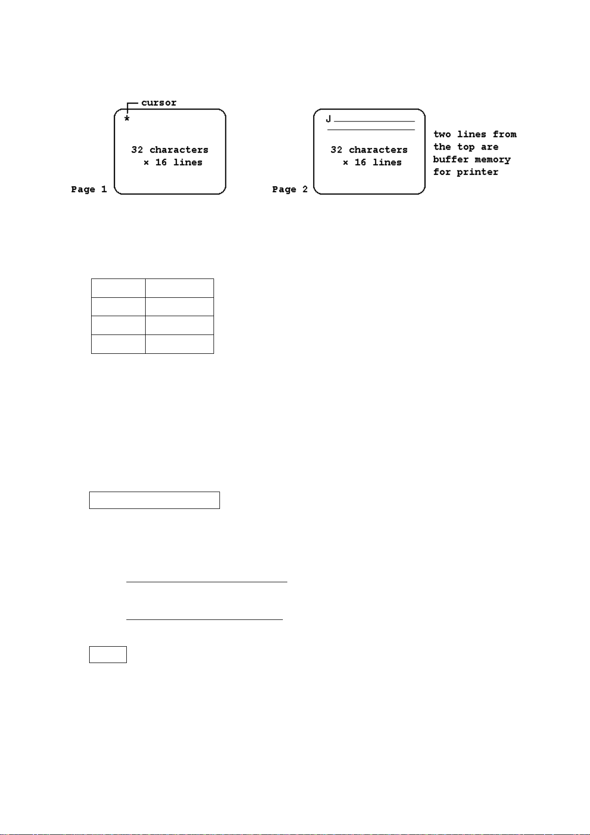
When you get LTR indicating LED light and indications on the TV screen as shown in Fig. 6A. your
Θ-350 is all ready to go!
Figure 6A Figure 6B
When in the POWER-ON-RESET or RESET STATE:
1. Speed
Mode Speed
MORSE Low Speed
BAUDOT 45.45 baud
ASCII 110 baud
2. WORD-WRAP-AROUND ------------ OFF
3. UNSHIFT-ON-SPACE ---------------- OFF
4. SCREEN --------------------------------- Page 1
5. CASE ------------------------------------- letters
6. "FF" ($0C) of ASCII is sent to the printer port on the CPU Board, which makes LF until next
TOF on the HC-800 & HC-900 printers.
iii) CW (Morse) Operation
Speed and Weight Setting
Speed is automatically determined. Dots which are less than 15 msec may be regarded as
noise. However, when slow CW is received right after rather quick CW, 2 to characters are
required before synchronization is archived.
For the faster sync in high speed:
Push any key of the middle row. (100, 110, 200, 300)
For the faster sync in low speed:
Push any key of the top row. (45, 50, 57, 74)
Tuning
Using LED indicator
1. Receive CW with the receiver.
2. SPACE indicating LED lights when the CW signal from the receiver pass through the
band-pass-filter of which the central frequency is 830 Hz.
3. Tuning VFO or RIT of the receiver so as to make this SPACE indicating LED have maxi-
mum brightness.
9
Page 12
TONO Θ-350 INSTRUCTION MANUAL
Using audio level
1. Set AF Switch to SPACE.
2. Output of the band-pass-filter is to be heard.
3. Adjust the receiver so that audio level of the Θ-350 may be maximum.
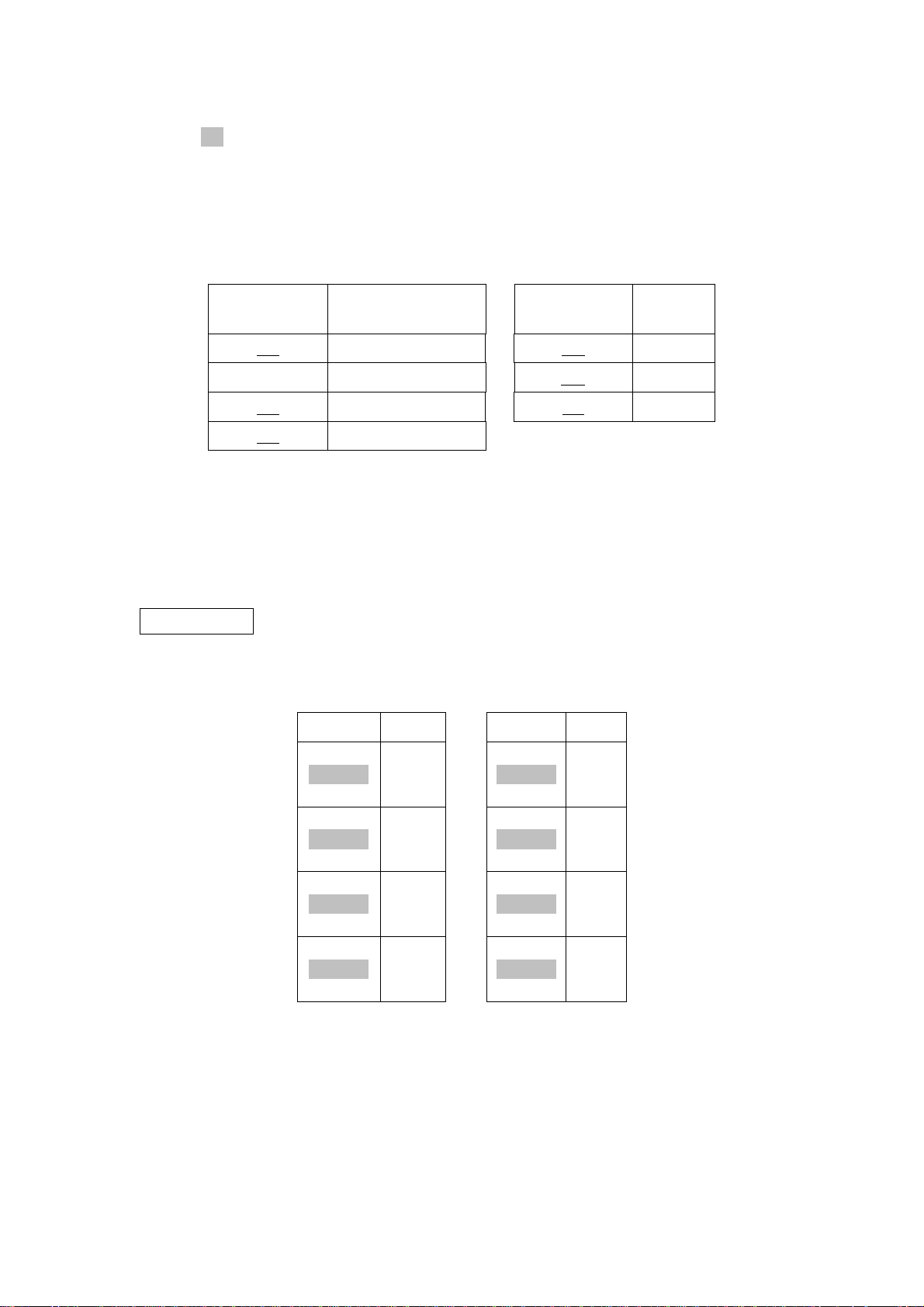
When the SPACE indicating LED begins to flicker corresponding to signals, the Θ-350
reads properly and will display on the TV screen. Special characters are to be displayed as
shown in Table 6.
SPECIAL
CHARACTER
BT = KN (
ERROR < AR +
AS ^ VA ;
AA @
NOTE: Mode change under running condition requires renewal of speed setting.
iv) RTTY (Baudot) Operation
Speed Setting
Speed is automatically set at 45.45 baud in the initial state. Refer to Table 7 for speed selection.
KEY BAUD KEY BAUD
DISPLAY
Table 6
SPECIAL
CHARACTER
DISPLAY
PAGE
[ ]4545.45
LOG
[ ]
50
WORD
50
[ ]5756.88
U.S.O.S.
[ ]7474.2
ENG
[ ]
100
CTRL
[ ]
110
UP
[ ]
200
DOWN
[ ]
300
100
110
200
300
Table 7
NOTE: 45.45 baud is popular among amateurs and 50 baud is widely used in busi-
ness communications.
10
Page 13

TONO Θ-350 INSTRUCTION MANUAL
Fine Adjustment: Press the following keys at the same moment:
[ ]
SHIFT
[ ]
SHIFT
UP
[ ]
200
DOWN
[ ]
300
Speed up
Speed down
(The length of a bit becomes
about 0.16 msec shorter per time.)
(The length of a bit becomes
about 0.16 msec longer per time.)
Tuning
1. Tune in RTTY signals with the receiver.
2. Increase the AF output frequency gradually from the lower value with the VFO or RIT,
until MARK indicating LED lights.
3. Continue increasing the frequency.
4. Stop increasing the frequency when the MARK indicating LED lights again and comes
to light at maximum brightness.
5. SPACE indicating LED lights at this moment when the shift width of RTTY signal agrees
with the setting of the Θ-350.
│
yes ──┴─ no If SPACE indicating LED does not light, turn the FINE tuning
│ control to catch the position where it lights. Go to 6.
│ If not
│ Change the setting so as to make SPACE indicating LED
│ lights and turn the FINE tuning control to make the lighting the
│ brightest.
──┘
6. Turn the FINE tuning control and stop it at the maximum brightness of SPACE indicat-
ing LED.
When tuning is completed, right characters are to be displayed on the screen. If not
Change the speed setting
and/or
Turn SENSE swich to REV
and/or
Input signals are judged not to be RTTY.
For amateur communication, 170 Hz shift is most commonly used; for business communication, 850 Hz and 425 Hz shift are widely used. In addition, monitoring of the output of MARK
filter and SPACE filter are obtainable by tuning AF switch to MARK/SPACE. The output of
MARK filter and SPACE filter can function in lieu of MARK indicating LED and SPACE indicating LED.
Tuning by Cross-Pattern
In the case of tuning with a cross-pattern made on the oscilloscope, adjust VFO and RIT of
a receiver and FINE tuning control of the Θ-350 to make amplitude both in V-direction and
H-direction the maximum.
NOTE: Mode change under running condition requires renewal of speed setting.
11
Page 14

TONO Θ-350 INSTRUCTION MANUAL
v) ASCII Operation
Speed Setting
Speed is automatically set at 110 baud in the initial state. Follow the RTTY methods for
speed change and selection.
Tuning
Follow the RTTY methods for tuning.
NOTE: Mode change under running condition requires renewal of speed setting.
vi) Special Functions
ANTI-NOISE Circuit
When there are too many errors caused be noise when there is no signal, set the ANTI-
NOISE switch to ON.
This circuit may make mistakes with high speed CW (Morse) of which a dot is shorter than
20 msec.
UNSHIFT-ON-SPACE Function (only in BAUDOT)
When error in CASE (LTR or FIG) is often made with a lot of noise, press [SHIFT] and
[U.S.O.S.] at the same moment. UNSHIFT-ON-SPACE functions works and leads the LTR
(Letter) case when space is received. To release this function, press these keys again.
CW (Morse) Practice
Connect a hand key with INPUT-TTL jack on the back panel. Set INPUT switch to TTL.
Manipulate the key and reading is gained and displayed on the screen. Monitoring sound
can be heard.
Recording of received signals
Recording during receiving is enabled by connecting PHONE jack of the Θ-350 with the mi-
crophone terminal of a tape recorder.
Automatic CR+LF after receiving
In several seconds after completion of receiving messages, CR+LF is made on the screen.
CR+LF signal is to be sent to the printer port automatically.
WORD-WRAP-AROUND
The word-wrap-around function prevents the last word of the line from splitting in two.
Press [SHIFT] and [WORD] at the same moment. To release this function, push these keys
again.
12
Page 15
TONO Θ-350 INSTRUCTION MANUAL
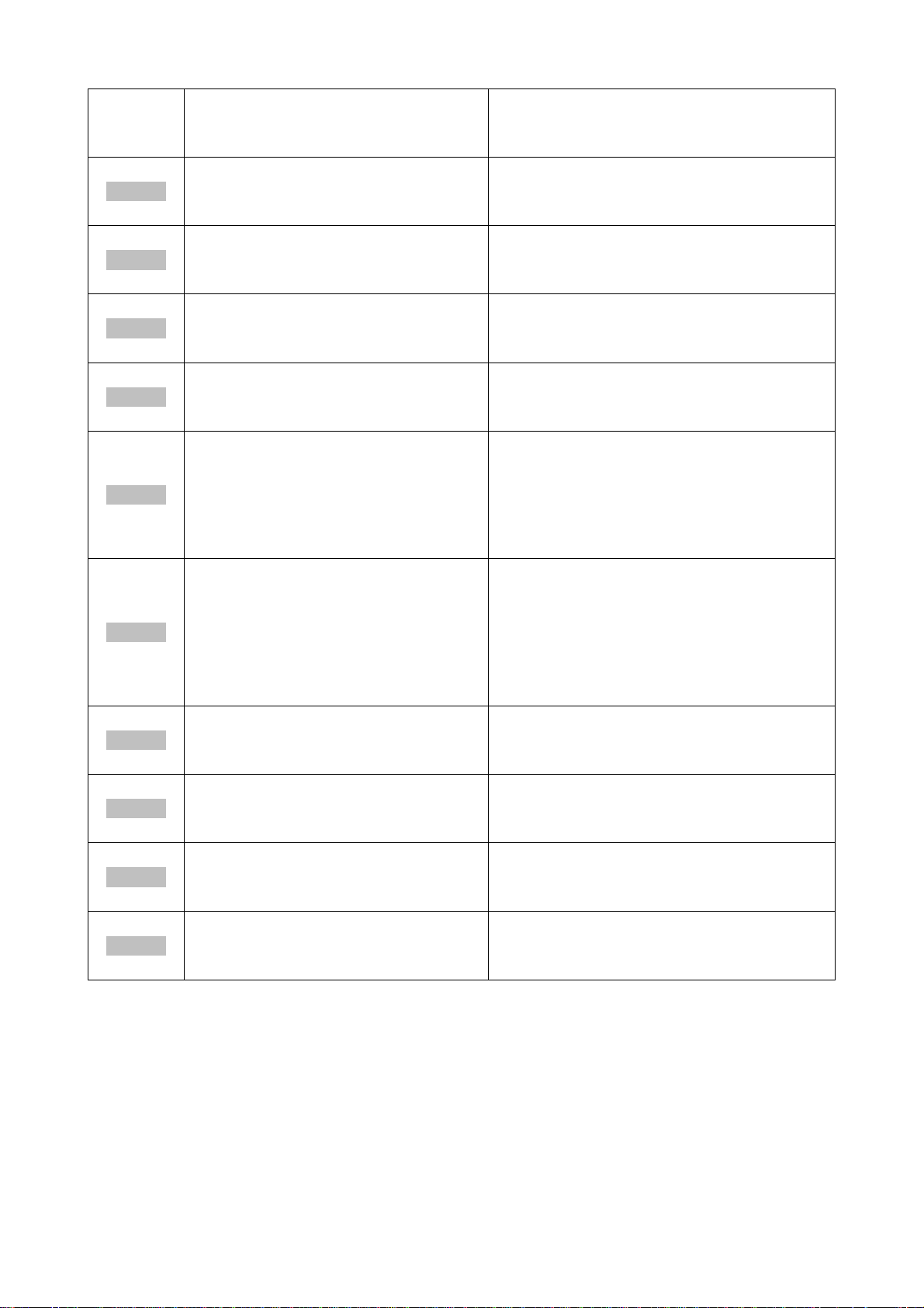
Push a respective
KEY UNSHIFT
SHIFT key together with
SHIFT key
PAGE
[ ]
45
LOG
[ ]
50
WORD
[ ]
57
U.S.O.S.
[ ]
74
ENG
[ ]
100
CTRL
[ ]
110
To set at 45.45 baud in RTTY and
ASCII. Or to set at Low Speed in
CW (Morse).
To set at 50 baud in RTTY and
ASCII. Or to set at Low Speed in
CW (Morse).
To set at 56.88 baud in RTTY and
ASCII. Or to set at Low Speed in
CW (Morse).
To set at 74.2 baud in RTTY and
ASCII. Or to set at Low Speed in
CW (Morse).
To set at 100 baud in RTTY and
ASCII. Or to set at High Speed in
CW (Morse).
To set at 110 baud in RTTY and
ASCII. Or to set at High Speed in
CW (Morse).
To change the page.
To set at 600 baud in ASCII
To switch WORD-WRAP-AROUND
function on/off.
To switch UNSHIFT-ON-SPACE
function on/off.
To send "ESC [" to make HC-900 in
incremental mode and "ESC ]" to make it
in logic seek mode by turns. In logic seek
mode it prints out line by line. When in
incremental mode it prints out immediately
after receipt of each signal.
In order to avoid printing on folding lines
of folded type paper it changes VFU of
printer. Adjust the printer head on the 4
th
line and power up the printer. Change VFU
by pressing these keys. The change of VFU
makes top three and bottom three lines
blank.
UP
[ ]
200
DOWN
[ ]
300
JPN
[ ]
CASE
CLEAR
[ ]
RETURN
To set at 200 baud in RTTY and
ASCII. Or to set at High Speed in
CW (Morse).
To set at 300 baud in RTTY and
ASCII. Or to set at High Speed in
CW (Morse).
To change CASE (LTR or FIG)
manually in RTTY (Baudot).
To make CR.LF on the screen and
send the ASCII signals of CR.LF
to the printer.
Table 8
To make the length of a bit about 0.16 msec
shorter per time in RTTY and ASCII.
To make the length of a bit about 0.15 msec
longer per time in RTTY and ASCII.
To send the signal of SO/SI to the printer:
HC-800 and HC-900 in order to make
the printings normal/large.
To clear the screen and the buffer for the
printer and send CR.LF signals to the
printer.
13
Page 16
TONO Θ-350 INSTRUCTION MANUAL
7. MAINTENANCE
1. When the Θ-350 stops working because of excessive or inverse power
Supply a new fuse on the Switch Board if a fuse is gone. The D18 Zener Diode on the CPU
Board is possibly destroyed, and in that case, supply a new 18 V (Zener Voltage) Zener Diode,
2. When the right display cannot be obtained on the screen because of the frequency of RF out-
put
Tune with the FINE tuning of the home TV set. If it doesn't work, adjust the trimmer capacitor
through the hole of the shield box on the CPU board.
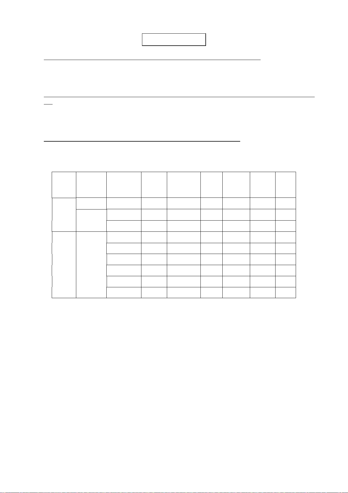
3. If the frequency of respective filters in the demodulator has changed
Adjust the respective variable resistor so that each amplitude at each test point should be as
follows:
Mode
sw
Filter
Tone
sw
Shift
Morse CW Filter --- --- 830 Hz TP6
MARK Low Tone --- 1275 Hz TP5
Signals
for
INPUT-AF
Test
Point
Amp.
2.0 V
1.6 V
Center
Freq.
VR13 VR14
p-p
VR11 VR12
p-p
Amp.
VR
Filter High Tone --- 2125 Hz TP5 --- VR10 ---
Baudot Low Tone 170 Hz 1440 Hz TP4
1.6 V
p-p
VR8 VR9
Low Tone 425 Hz 1700 Hz TP4 --- VR7 ---
SPACE Low Tone 850 Hz 2125 Hz TP4 --- VR6 ---
Filter High Tone 170 Hz 2295 Hz TP4 --- VR5 ---
High Tone 425 Hz 2550 Hz TP4 --- VR4 ---
High Tone 850 Hz 2995 Hz TP4 --- VR3 ---
Table 9
i) AF input signals = 0.5 V
p-p
.
ii) Fine tuning potentiometer should be accurately adjusted at the center.
iii) Make an adjustment with the center freq tuning variable resistor so as to have the
maximum amplitude, and then, adjust with the amplitude tuning variable resistor so
as to have the proper amplitude.
14
Page 17

TONO Θ-350 INSTRUCTION MANUAL
8. SPECIFICATIONS
1. Code:
Morse Code (CW), Baudot Code (RTTY), ASCII
2. Character:
Alphabet, Figures, Symbols, Special characters
3. Receiving Speed:
[CW Receiving] 25 – 250 characters/min. (Automatic track)
[RTTY " ] 45.45, 50, 56.88, 74.2, 100, 110, 200,, 300 Baud (Fine adjustment available)
[ASCII " ] same as RTTY
4. Input:
[AF Input] Impedance 500 ohms
[TTL Level Input] common to CW, RTTY, ASCII
5. AF Input Frequency:
[CW] 830 Hz
[RTTY] Mark: 1275 Hz (Low Tone), 2125 Hz (High Tone) ┐
Shift: 170 Hz, 425 Hz, 850 Hz and Fine Tuning ┘
[ASCII] same as RTTY
6. Display Output:
[VHF Output Impedance] 75 ohms
[Composite Video Signals Output Impedance] 75 ohms
7. Printer Interface:
Centronics Parallel Compatible
8. Number of Characters and Pages to be Displayed:
512 characters ( 32 characters × 16 lines) / page × 2 (Total: 1024 characters)
9. Output for Oscilloscope:
or rev.
Output Impedance 200 kilo-ohms
10. AF Output:
150 mW, Output Impedance 8 ohms
11. Power Supply:
DC +12 V, 0.8 A
NOTE: All of the features and specifications are subject to change without notice.
15
Page 18
TONO Θ-350 INSTRUCTION MANUAL
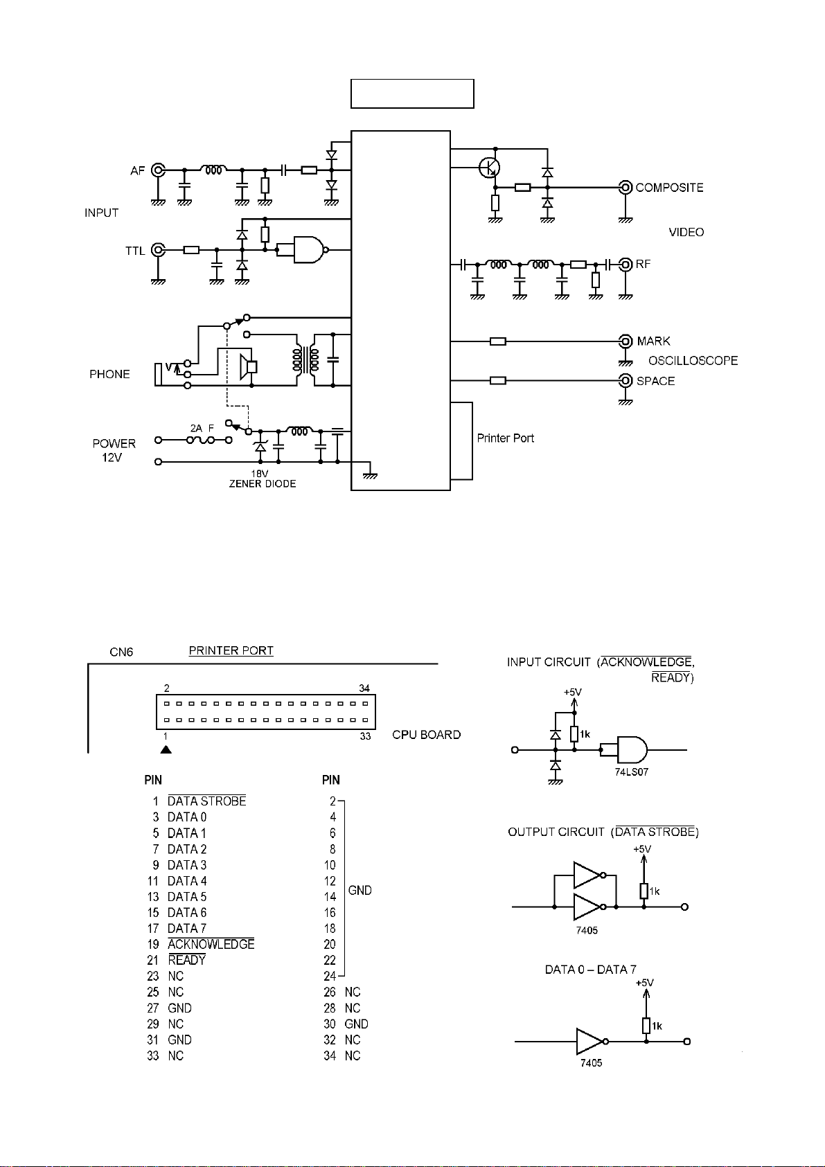
9. I/O CIRCUIT
16
 Loading...